9. OPTIONAL ITEMS
Contact suppressor connection diagram
Suppressor
A1
A2
A1 A2 are theand
contactor coils.
Diagram for suppressor installation for direct
drive load inputs
Load
Suppressor
For direct activation the maximum
specified current should be taken
into consideration.
Electrical noise suppressing filter
8. SIGNALLING
Temperature sensor disconnected or damaged.
Functions lockdown.
Unlocking of functions.
Reconfigure the values of the functions.
Humidity sensor disconnected or damaged.
Buzzer inhibitor.
Receiving preset.
Operation successful.
Control functions shutdown.
[tErr]
[hErr]
[LOC,][0n,,]
[LOC,][0FF,]
[Inib]
[SPCr]
[done]
Please contact Full Gauge Controls.
RC FILTER
IMPORTANT
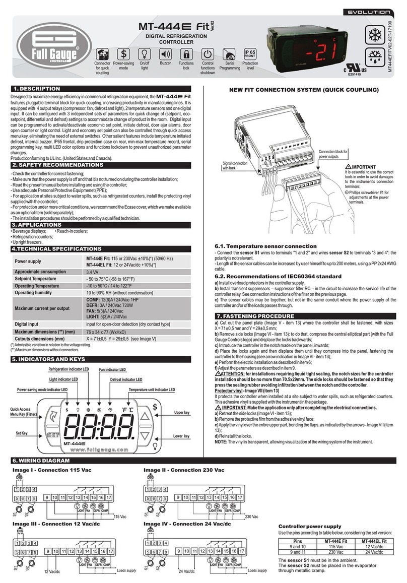
According to the chapters from the IEC60364 standard:
1: Install on power supplyprotectors against over voltage
2: Sensor cables and computer signals can be together, however not at the same place where power
supply and load wires pass for
3: Install suppresor of transient in parallel to loads to increase the usefull life of the relays
Note: The sensor cable length can be increased by the user until 200 meters using 5x22AWG
(-40+105°C) cable.
Ecase protective cover
It is recommended for the Evolution line, keeps water
from entering the back part of the instrument. It also
protects the product when the installation site is
washed.
ECASE PROTECTIVE COVER
Extended frame
It allows the installation of Evolution line controllers
with sizes 76 x 34 x 77 mm in various situations,
since it does not require precision in the notch of
the instrument fitting panel.
The frame integrates two switches of 10 Amperes
that may be used to actuate interior light, air
curtain, fan, and others.
CONTROLLER
EXTENDED
FRAME
SWITCHES
- version 2EasyProg
It is an accessory that has as its main function to store the parameters of the controllers.At any time, you
can load new parameters of a controller and unload them on a production line (of the same controller),
for example. It has three types of connections to load or unload the parameters:
- Serial RS-485: It connects via RS-485 network to the controller (only
for controllers that have RS-485).
- USB: it can be connected to the computer via the USB port, using
Sitrad's Recipe Editor.
- Serial TTL: The controller can be connected directly to EasyProg
by the TTL Serial connection. EASYPROG
IMPORTANT
TO PERFORM THE COMMUNICATION
WITH EASYPROG THIS EQUIPMENT MUST
NOT BE COMMUNICATING WITH SITRAD
SOFTWARE.
F29 - Acting point of Buzzer by low temperature:
It is the minimun temperature to trigger the buzzer the configured Operation Mode of Buzzer .[,F28]
F30 - Acting point of Buzzer by high temperature:
It is the superior value of temperature to the buzzer alarm act as the configured Operation Mode of
Buzzer .[,F28]
F31 - Acting point of Buzzer by low humidity:
It is the inferior value of humidity to the buzzer alarm act as the configured Operation Mode of Buzzer
[,F28].
F32 - Acting point of Buzzer by high humidity:
It is the superior value of humidity to the buzzer alarm act as the configured Operation Mode of Buzzer
[,F28].
F33 - Maximum time of the activated THERM output to activate the alarm:
Allows configuring the maximum time the output THERM can stay activated without reaching the
setpoint before activating the audible alarm (BUZZER). To deactivate this function, just decrement the
value until the message is displayed.[no,,]
F34 - Maximum time of the activated HUMID output to activate the alarm:
Allows configuring the maximum time the output can stay activated without reaching theHUMID
setpoint before activating the audible alarm (BUZZER). To deactivate this function, just decrement the
value until the message is displayed.[no,,]
F35 - Maximum time of the activated AUX output to activate the alarm:
Allows configuring the maximum time the output AUX can stay activated without reaching the setpoint
before activating the audible alarm (BUZZER). To deactivate this function, just decrement the value
until the message is displayed.[no,,]
F36 -Buzzer time on:
It is the time that the Buzzer will be turned on (cycle on). To turn it off the sonore alarm (Buzzer) adjust
the value “0” to this function.
F37 - Buzzer time off:
It is the time that the buzzer will be turned off (cycle off). To turn the sonore alarm (Buzzer) always on,
adjust the value “0” to this function.
F38 - Inhibition time of Buzzer during electrical supply:
It is the time were the alarm will kept turned off even if in alarm contitions.
It serves to inhibit the buzzer during the time while the system do not reaches the working control
temperature.
F3 - Output status in case of alarm9:
[,,,0]Status output do not change in case of alarm;
[,,,1]Turn off the output THERM, HUMID and AUX;
Note: TheAUX output will not turn off if it is set to alarm output intra-extra range yclic timer In case ofor c .
sensor failure the outputs will be switched off independently of the parameter settled in that function.
F40 - Thermostat cooling time (interval between defrosts):
Corresponds to the time that the controller will operate in refrigeration, at the end of this time the
controller enters the defrost process.
F41 - Thermostat defrost time:
It is the duration of the defrost. During this period, the relay will remain off, at the end of which, the
controller will return to the refrigeration state.
Note: During the defrost process, high/low temperature alarms are disregarded.
F42 - Initial state of the thermostat when powering up the controller:
It makes it possible to perform a defrost when the controller is energized.
F43 - Additional time at the end of the first refrigeration cycle:
It serves to increase the refrigeration time only in the first refrigeration cycle. In installations with several
pieces of equipment, it is possible to avoid demand peaks, causing the defrosts to be carried out at
different times, by assigning different values to this function.
Note: The defrost parameters ( to ) apply only to the main thermostat (THERM[,F40] [,F43]
output). The defrost functionalities are only available if the THERM output is configured as cooling
( = 0) and the thermostat defrost time is different from .[,f03] [,f41] [OFF,]
F44 - Display mode:
[,,,0]Alternated indication of temperature and humidity
[,,,1]Only indication of temperature
[,,,2]Only indication of humidity
F45 - Temperature display offset:
It allows to compensate eventual shunting lines in the reading of temperature proceeding from the
exchange of the sensor or cable length alteration.
F46 - Humidity display offset:
It allows to compensate eventual shunting lines in the reading of humidity proceeding from the
exchange of the sensor or cable length alteration.
F47 - Function lock mode:
Allows and configures the blocking of functions (see item 6.3.2).
[,,,0]: Does not allow blocking of functions;
[,,,1]: Allows the partial blocking, where the control functions will be blocked but the setpoints
adjustment remain released;
[,,,2]: Enables total blocking, leaving only access to the facilitated menu functions available.
F48 - Time for blocking functions
With this functionality active, the parameters are protected against undue changes, making them
available only for viewing. In this condition, when trying to change these values, the message
[LOC,,] will be shown on the display.
F49 - Shutdown of control functions:
With the shutdown of the control functions, the controller starts to operate only as a temperature
indicator with all the outputs turned off. This function can operate in the following ways:
[Off,]: Does not allow turning off the control functions;
[,,,1]:Allows turning on and off the control functions only if the functions are unlocked;
[,,,2]:Allows you to turn control functions on and off even if the functions are blocked.
F50 - Network equipment address:
This is the device address for communication with software.Sitrad®
Note: You cannot have two or more devices with the same address in the network.
[Off,]
[eCal]
[pppp]
