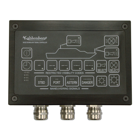
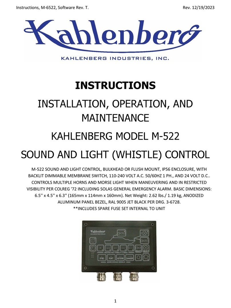
Kahlenberg M-485B User manual

M-485B Horn Signal Controller Instructions Rev. 4/12/2022
www.kahlenberg.com Customer Support: 1-920-793-4507
INSTRUCTIONS
INSTALLATION, OPERATION, AND MAINTENANCE
KAHLENBERG MODEL M-485B
HORN SIGNAL CONTROLLER
P.N. TI/37575/DC/ABC
M-485B SIGNAL CONTROLLER, FOG SIGNAL TIMER AND WHISTLE CONTROL, 12 OR 24 VOLT D.C.,
WITH ILLUMINATED M-129 TWO POSITION PANEL ROCKER SWITCH. INCLUDES FOG SIGNAL CODES
(RULE 35) FOR "UNDERWAY" AND "STOPPED", MOTOR AND SAILING VESSELS, PER IMO "COLREG
72" AND COMDTINST M16672.2D, PER DRG. 3-7575
PLEASE READ INSTRUCTIONS IN THEIR ENTIRETY
BEFORE PROCEEDING. INCORRECT INSTALLATION
WILL PERMANENTLY DAMAGE THIS UNIT!

M-485B Horn Signal Controller Instructions Rev. 4/12/2022
www.kahlenberg.com Customer Support: 1-920-793-4507
Table of Contents Page
Introduction 1
Important Safety Instructions 2
General Description 2-3
Package Contents 3
Electrical Requirements 3
Performance and Technical Data 3
Installation 4-7
Operation 7-8
Maintenance 8
Storage 8
Reference Document List 8
Troubleshooting 9
Drawings 10-15
WARNING! This instruction manual
contains important instructions for
operating this product. Read this manual
thoroughly before operating the product.
Failure to properly follow all the
instructions and precautions can cause
serious injury or death.
Thank you for purchasing a Kahlenberg
Industries product. Please contact us if you
have any questions.
Record the model and serial numbers from
your product’s nameplate below for future
reference:
Model No.:_________________________
Serial No.:__________________________
Date of Purchase:____________________

M-485B Horn Signal Controller Instructions Rev. 4/12/2022
www.kahlenberg.com Customer Support: 1-920-793-4507
IMPORTANT SAFETY INSTRUCTIONS
WARNING
SHOCK
There is a danger of electric shock.
DO NOT service this product in wet weather or
wet conditions.
DO NOT service this product if hands or feet are
wet.
Ensure you have sufficient electrical supply for
supporting the requirements of this product.
ALWAYS remove and lock out/tag out electrical
power before performing maintenance.
GENERAL DESCRIPTION
The M-485B Horn Signal Controller is a solid-state control for automating sound signals
in conditions of restricted visibility (fog signals) as prescribed by International
Navigation Rules (IMO) COLREGS Part D, Rule 35. The M-485B will output signals for a
vessel “Underway”, or “Underway but stopped”.
The M-485B is configured from the factory to activate an electric solenoid valve that
matches the supply voltage of the M-485B. (12 or 24 Volt D.C.) The solenoid valve
opens the air line to an air horn. The M-485B can also be changed internally to activate
a 12 or 24 volt D.C. Electric Horn.
NOTE: THE M-485B CAN NOT BE CONNECTED DIRECTLY TO AIR HORNS THAT
ARE POWERED BY SMALL ROTARY “BEAN CAN” COMPRESSORS. THESE
COMPRESSORS DRAW HIGH AMPERAGE (OVER 10 AMPS) WHICH WILL
PERMANENTLY DAMAGE THE M-485B CONTROLLER.

M-485B Horn Signal Controller Instructions Rev. 4/12/2022
www.kahlenberg.com Customer Support: 1-920-793-4507
Signal codes produced by the M-485B, and their COLREG references include:
a.) One Long Blast (4-6 seconds)
“A power-driven vessel making way through the water shall sound at intervals of
not more than 2 minutes, 1 prolonged blast.”
b.) Two Long Blasts (4-6 seconds each)
“A power-driven vessel underway but stopped and making no way through the
water shall sound at intervals of not more than 2 minutes two prolonged blasts in
succession with an interval of about 2 seconds between them.”
c.) One Long and Two Short Blasts
“A vessel not under command, a vessel restricted in her ability to maneuver, a
vessel constrained by her draught, a sailing vessel, a vessel engaged in fishing and
a vessel engaged in towing or pushing another vessel, shall, instead of the signals
prescribed in paragraphs (a) or (b) of this Rule, sound at intervals of not more
than 2 minutes, three blasts in succession, namely one prolonged followed by two
short blasts.
PACKAGE CONTENTS
The M-485B Horn Signal Controller is assembled and shipped complete, including cables for
connection to the horn, main power, and Model M-129 Rocker Switch. Enclosed in a separate
poly bag taped to the M-485B are the M-129 Rocker Switch, P548-04 Mounting Bezel, and
P356-11 Nameplate. There are no other loose items in the shipment other than included
instructions.
ELECTRICAL POWER REQUIREMENTS
Main Power circuit for M-485B: 12-24 Volts D.C., +30%,-10%
Maximum Current Required: 2 Amps @ 12 Volts
PERFORMANCE AND OTHER TECHNICAL DATA
Output Relay
Max. Switching Current: 5 Amps @ 30 Volts D.C.
Rated Carry Current: 10 Amps
Ingress Protection: IP66 (M-129 Switch assembly only), IP 60 Enclosure
Weight: 1 lbs, (0.45 kg)
Dimensions: 7.29” x 4.34” x 1.85” (186 x 111 x 47mm)
Installation Environment: Protected from weather, code B, IEC60945 (Enclosure Only)
Exposed to weather, code C, IEC60945 (Switch Assembly Only)

M-485B Horn Signal Controller Instructions Rev. 4/12/2022
www.kahlenberg.com Customer Support: 1-920-793-4507
INSTALLATION
Initial Setup:
Internal to the M-485A there is a jumper located at position J2 on the circuit board as shown
below. The jumper is in this position as shipped from the factory. The restricted visibility
codes in the M-485B are set for “MOTOR” vessels.

M-485B Horn Signal Controller Instructions Rev. 4/12/2022
www.kahlenberg.com Customer Support: 1-920-793-4507
To change the M-485B output to the restricted visibility codes for “SAIL” vessels, gently pull the
jumper up off the pins and move it, to disconnect the jumper circuit as shown below.
**NOTE: When moving the jumper to make changes the unit must also be re-powered for this
change to take effect

M-485B Horn Signal Controller Instructions Rev. 4/12/2022
www.kahlenberg.com Customer Support: 1-920-793-4507
Location and Mounting:
The M-485B Enclosure must be installed in a location protected from weather, inside the main
control console, within appx. 2-1/2 feet of the intended switch location. Three feet (0.9M) of
switch cable harness is provided. Extra length of this cable can be provided upon request. See
drawing 3-7575 for mounting hole size and locations on the enclosure.
The M-129 Rocker Switch is intended for installation in the P548-04 mounting bezel, which is
installed in the console switch panel. The P548-04 mounting bezel allows for installation in
panel material thickness of .062” (1.57mm) to .375” (9.52 mm) thickness.
1.) The hole in the panel should be cut per the switch cutout depicted on drawing 3-7575.
NOTE: If the switch is to be used without the P548-04 mounting bezel, the hole will
need to be smaller! Verify dimensions before cutting!
2.) Clean the console panel surface. Remove adhesive backing, align and install the P356-
11 Nameplate on the panel.
3.) Verify that the wiring harness switch connections can be pulled up through the panel to
connect the switch.
4.) Apply marine silicone sealant to the panel surface to seal the bezel.
5.) Mount the P548-04 Bezel in the hole and wipe off excess sealant.
6.) Bring the wire harness from the M-485B through the hole and make connections to the
M-129 Switch per wiring diagram enclosed.
7.) Verify correct operation in the following sections before installing M-129 Switch into
P548-04 Bezel. Once the switch is installed in the bezel it is very difficult to remove.

M-485B Horn Signal Controller Instructions Rev. 4/12/2022
www.kahlenberg.com Customer Support: 1-920-793-4507
Connections:
Electrical:
If the M-485B will be connected to an air horn solenoid valve of the same voltage
:
All internal connections have been made in the M-485B at the factory to use the incoming M-
485B main power for the internal relay which supplies current to the horn. Make connections
according to wiring diagram 3-7584, or wiring diagram 3-7577 if the Kahlenberg M-130 double
pole “at will” horn switch is also used in the system (available separately).
If the M-485B will be connected to a 12 or 24 Volt D.C. Electric Horn
(Max. 10 Amps @ 12 volts D.C.
)
1.) See wiring diagram 3-7597, or wiring diagram 3-7582 if the Kahlenberg M-130 double
pole “at will” horn switch is also used in the system (available separately).
2.) Open the M-485B Enclosure and remove the red jumper wire between terminal blocks J1
and J8.
3.) Remove the black horn cable wire from 4th terminal location on J1, and install it in
terminal J8, 3rd terminal location right next to the existing red horn cable wire.
4.) Make connections according to wiring diagram 3-7597, or wiring diagram 3-7582 if the
Kahlenberg M-130 double pole “at will” horn switch is also used in the system.
NOTE: THE M-485B CAN NOT BE CONNECTED DIRECTLY TO AIR HORNS THAT
ARE POWERED BY SMALL ROTARY “BEAN CAN” COMPRESSORS. THESE
COMPRESSORS DRAW HIGH AMPERAGE (OVER 10 AMPS) WHICH WILL
PERMANENTLY DAMAGE THE M-485B CONTROLLER.
OPERATION
Verify all wiring connections are complete and M-129 Rocker Switch is in the middle (off)
position. Turn on main power circuit breaker. Turn on relay power breaker (if installing with an
electric horn per wiring diagrams 3-7582 or 3-7597).
1.) Move M-129 Switch to “Underway” position. The corresponding amber LED light on
the switch should illuminate, and when set internally for a Motor Vessel, the M-485B
should immediately sound the horn for 1 long blast (appx. 4 seconds), and repeat every
two minutes. If the internal jumper in the M-485B was moved to “Sail” position, horn
should immediately sound 1 long blast, followed by two short blasts, and repeat every
two minutes.

M-485B Horn Signal Controller Instructions Rev. 4/12/2022
www.kahlenberg.com Customer Support: 1-920-793-4507
2.) Move the switch to the center “OFF” position. The LED light on the switch should turn
off. The M-485B is now off and horn sounding should stop.
3.) Move the switch to the bottom “Stopped” position. The corresponding amber LED light
on the switch should illuminate, and the M-485B should immediately sound the horn for
2 long blasts (appx. 4 seconds each), and repeat every two minutes.
4.) While the M-485B is operating either “Stopped” or “Underway” codes, press the “At-Will”
horn button on the vessel. The horn should sound. If the “At-Will” button is the
Kahlenberg M-130 Horn Button, the horn should sound, AND the M-485B Controller
should stop the automated signal pattern currently in operation. The LEDs on the
switch should also begin flashing. The flashing indicates that the M-485A automated
signal pattern has been interrupted. To reset the M-485A, move the rocker switch to
the center “Off” position. If the “At-Will” button on the vessel is a standard single pole
switch, the horn should sound when it is depressed, but the automated signal code will
continue to sound the horn uninterrupted on the M-485B.
MAINTENANCE
The M-485B is a solid state unit and is not user serviceable. Contact Kahlenberg Industries for
any replacement parts that may be needed. Please have model number and serial number of
the unit available when contacting us for assistance.
STORAGE
If storing the M-485B for an extended period of time, store indoors at temperatures above 32
deg. F./0 deg. C., and poly bag and package package the items with silica desiccant packets to
protect from dust and excessive moisture.
Reference Documents:
Outline Dimensions, M-485B Horn Signal Controller
Drawing 3-7575
Parts List, M-485B Horn Signal Controller
Drawing 3-7576
Wiring Diagram, Installation with Air Horn and single pole
“At-Will” Button
Drawing 3-7584
Wiring Diagram, Installation with Air Horn and M-130 double pole
“At Will” Push Button
Drawing 3-7577
Wiring Diagram, Installation with Electric Horn and single pole
“At Will” Push Button
Drawing 3-7597
Wiring Diagram, Installation with Electric Horn and M-130 double
pole “At Will” Push Button
Drawing 3-7582
TROUBLESHOOTING

M-485B Horn Signal Controller Instructions Rev. 4/12/2022
www.kahlenberg.com Customer Support: 1-920-793-4507
PROBLEM
POSSIBLE CAUSE
POSSIBLE SOLUTIONS
M-485B is not functioning
Blown Fuse
Incorrect wiring
See 2 Amp fuse on main
circuit board. If fuse is blown,
unit is drawing too much
amperage. See “Electrical
Connections” section, verify
wiring is correct for air horn
vs. electric horn.
M-485B is sending current to
solenoid valve but air horn is
not sounding
Solenoid Valve voltage does
not match incoming M-485B
voltage.
Replace solenoid valve with
correct voltage requirement.
M-485B is sending current to
solenoid valve but air horn is
not sounding
Solenoid valve body is
installed backwards in air line.
Verify solenoid valve
installation is correct. An
arrow on the valve body
indicates correct air flow
direction, or “1” stamped on
the valve is air inlet, “2” on
the valve is outlet to horn.
M-485B Signals are not
sounding correctly (PCB resets
after every horn blast)
Incorrect Wiring
Correct Wiring. Verify if using
wiring diagram 3-7584 or 3-
7577 that the red jumper wire
from J1 to J8 is in the 3rd
terminal on J8, and the wire
out from J8 to valve is in the
4th terminal. If these wires
are reversed, signals will not
sound correctly.
Kahlenberg Industries, Inc.
1700 12th St., P.O. Box 358
Two Rivers, WI 54241 USA
Ph: 1-920-793-4507
Fx: 1-920-793-1346
info@kahlenberg.com


Table of contents
Other Kahlenberg Controllers manuals
Popular Controllers manuals by other brands

National Instruments
National Instruments cDAQ-9133 user manual

Smarteh
Smarteh LPC-2.MB1 user manual

Festo
Festo CMMO-ST-C5-1-LKP Original instructions

Excelitas Technologies
Excelitas Technologies OmniCure LX500 Installation reference guide

SRS Light Design
SRS Light Design RMCseries instruction manual

Infranor
Infranor SMT-BD1 Series operating manual

SMC Networks
SMC Networks AR20 Series Operation manual

Rodix
Rodix 121-000-0881 quick start guide

Mitsubishi Electric
Mitsubishi Electric FX3U-4AD-PTW-ADP user manual

Jamara
Jamara COOL RUNNING 081458 Instruction

C-LOGIC
C-LOGIC 500-PC instruction manual

Conrad Electronic
Conrad Electronic KW-9015 operating instructions