manuals.online logo
Brands
  1. Home
  2. •
  3. Brands
  4. •
  5. Kostal
  6. •
  7. Controllers
  8. •
  9. Kostal INVEOR M How to use

Kostal INVEOR M How to use

Short manual
Distributor for:
Functional safety
INVEOR M / MP
Thank you for choosing to work with EPA!
EPA - your competent partner for KOSTAL when it comes
to individual service &comprehensive services.
If you have any questions about the product, please feel free
to call us: Tel: +49 (0)6181 – 9704 – 0
You can nd the latest information about us and our products at
www.epa.de.
Sales department: EPA GmbH
Fliederstraße 8, D-63486 Bruchköbel
Deutschland / Germany
Telefon / Phone: +49(0)6181 9704-0
Telefax / Fax: +49(0)6181 9704-99
E-Mail: [email protected]
Internet: www.epa.de
Author: KOSTAL Industrie Electrik GmbH
Release: 06.2020
Article: INVEOR M / MP
EPA Drives
Legal notice
Direct link to operating manual
KOSTAL Industrie Elektrik GmbH
An der Bellmerei 10
58513 Lüdenscheid
Germany
Phone +49 (0)2351 16-0
Fax + 49 (0)2351 16-2400
[email protected]
Exclusion of liability
All names, trademarks, product names or other designations given in this manual may
be legally protected even if this is not labelled as such (e.g. as a trademark). KOSTAL
Industrie Elektrik GmbH accepts no liability and gives no assurance that they can be
freely used. The illustrations and texts have been compiled with great care. However,
the possibility of errors cannot be ruled out. The compilation is made without any
guarantee.
General note on gender equality
KOSTAL Industrie Elektrik GmbH is aware of the importance of language with regard to
the equality of women and men and always makes an effort to reflect this in the
documentation. Nevertheless, for the sake of readability we are unable to use non-
gender-specific terms throughout and use the masculine form instead.
© 2019 KOSTAL Industrie Elektrik GmbH
All rights reserved by KOSTAL Industrie Elektrik GmbH, including those of reproduction
by photocopy and storage in electronic media. Commercial use or distribution of the
texts, displayed models, diagrams and photographs appearing in this product is not
permitted.
This manual may not be reproduced, stored, transmitted or translated in any form or by
means of any medium - in whole or in part - without prior written permission.
The chapters marked with this symbol form part of the
complete operating manual.
Please read and note the information provided there.
Complete operating manual
You will find a detailed operating manual on “Functional safety”, including
application examples, online at
http://www.kostal-industrie-elektrik.com/INVEOR_M_Functional_Safety
Proper use
Proper use
IMPORTANT INFORMATION
Using drive controllers in equipment that is not fixed is considered as an
exceptional environmental condition and is only permitted if allowed by the
standards and guidelines applicable on site.
Only allow appropriately qualified staff to undertake assembly and disassembly.
Only use staff who are trained in mounting, installation, commissioning and
handling.
Do not modify the drive controller.
Observe general and national safety and accident prevention regulations
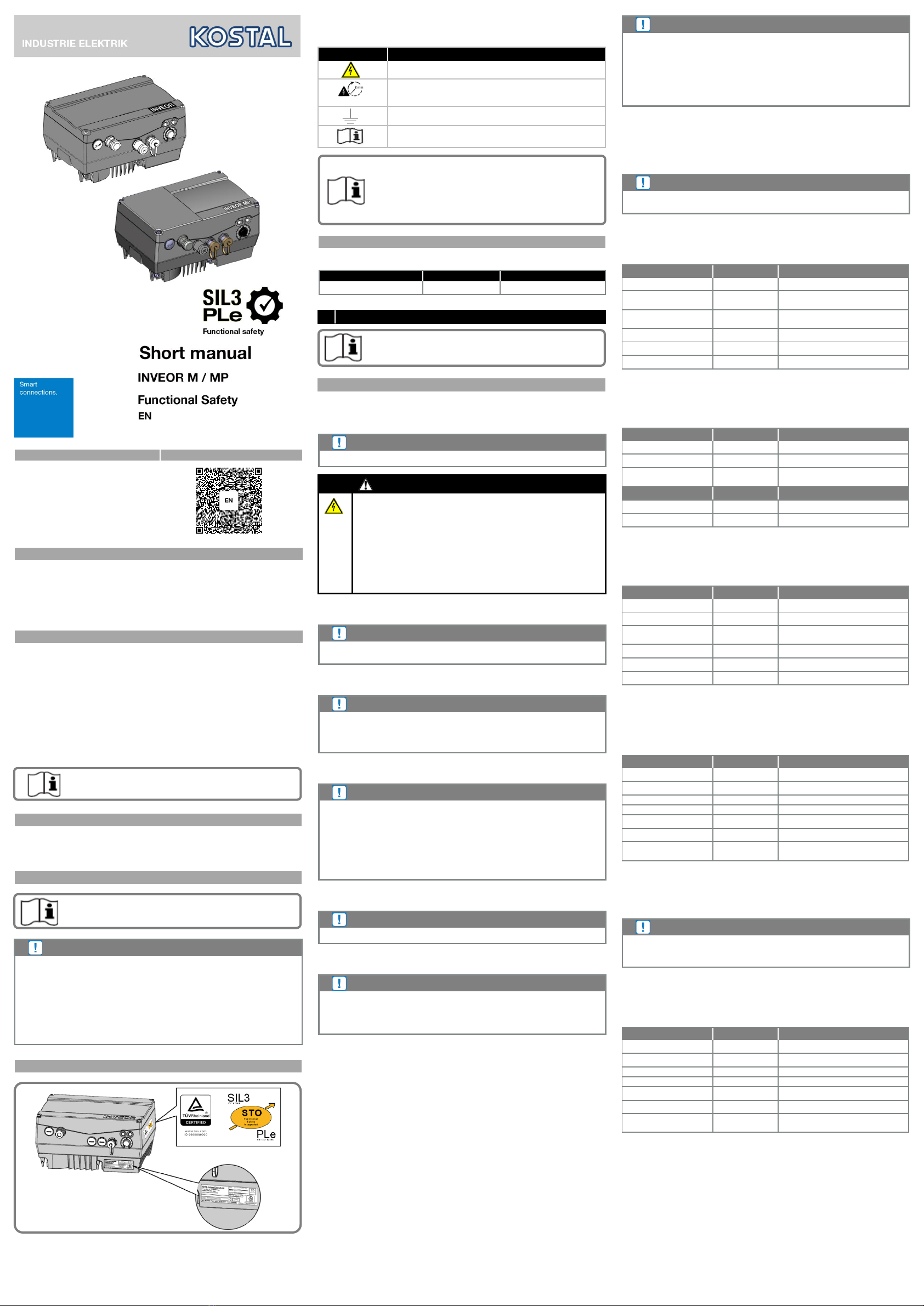
Labels on the drive controller
Signs and labels are applied to the housing of the drive controller.
These signs and labels may not be altered or removed.
Symbol
Meaning
Danger due to electrical shock and discharge
Danger due to electrical shock and discharge.
Wait two minutes (discharge time of the capacitors) after shut-
down
Additional earth connection
Observe and read operating manual

Qualified staff
Proper use
Responsibility
CE marking

Abbreviations used

Certificate
Contact details and service
If you have any technical questions, please contact our service hotline.
Country
Phone
E-mail
Germany and other countries +49 (0)2331 80 40-848 INVEOR-[email protected]
1 SAFETY INSTRUCTIONS
General safety instructions
STO safety instructions
The safety instructions listed in the following are to be observed and obeyed strictly.
Protection from electric shock
IMPORTANT INFORMATION
No protection from electric shock is ensured by the STO status.
DANGER!
Risk of death due to electrical shock!
Death or serious injury!
De-energise drive controller and secure it against being restarted.
The following terminals may lead to dangerous currents even when the
motor is not running:
Supply terminals X1: L1, L2, L3
Motor connection terminals X2: U, V, W
Connecting terminals X6, X7: Relay contacts for relays 1 and 2
PTC terminals T1/T2
Protection from contamination
IMPORTANT INFORMATION
With open housing, contamination degree 2 must be observed in order to ensure
the safety function.
Elimination of errors
IMPORTANT INFORMATION
The STO connection line must be shielded in order to allow the elimination of
errors with regard to external voltage coupling to be applied. The EMC screw
connection provided must be used for
the cable inlet into the INVEOR housing.
Elimination of errors with regard to short circuit
IMPORTANT INFORMATION
With reference to the STO connection line, the “elimination of errors with regard to
short circuit“ is achieved in accordance with DIN EN 13849-2 in that a separate,
shielded cable is used for each channel. Shielding is to be applied at both ends.
The EMC screw connections provided must be used
for this purpose.
If only one shielded cable is used for both STO channels, a safety switch must be
used to detect possible crossovers between the channels to qualify for observation
of the “elimination of errors short circuit“ in accordance with DIN EN 13849-2.
Loss of the safety functions
IMPORTANT INFORMATION
Permanent 24 V voltage to the STO inputs results in the loss of the safety function.
Classification IEC 60204-1
IMPORTANT INFORMATION
The process for the shut-down of the machine drive elements described under
“Stop category-1“ (SS1) can only be realised in connection with an additional
external safety module!

“Stop category-2“ (SS2) is not supported by the drive controller.
Classification IEC 61800-5-2
The following definitions describe the three types of safe stop function.
STO (Safe Torque Off)
No power is supplied to the motor that could cause rotation (or movement in the case
of a linear motor). The drive controller supplies no power to the motor that could
generate torque (or force in the case of a linear motor). This safety function
corresponds to an uncontrolled shut-down according to IEC 60204-1, stop category 0.
IMPORTANT INFORMATION
This safety function can be used when it is necessary to shut off power in order
to prevent an unexpected start.
Where there are external influences (e.g. falling of suspended loads), additional
measures (e.g. mechanical braking), which must be designed to fail safe, may be
necessary to prevent hazards.
In the STO status, the drive is not separated from the energy supply, as only the
activation of the IGBTs is securely switched off.
Safe Stop 1 SS1
The SS1 safety function corresponds to an uncontrolled shut-down according to
IEC 602,04-1, stop category 1. In this case the drive controller does not securely
monitor the motor delay or the motor speed.
IMPORTANT INFORMATION
Secure monitoring of the motor delay is only possible with the use of an external
safety module.
Classification of two-channel EN 62061 without external diagnosis
The classification of the two-channel STO function without external diagnosis meets
the following requirements:
Designation Value Explanation
Safety measure Pulse block ---
SIL
3
Safety
integrity level
PFH
1.81e-08
Probability of hazardous failures
per hour
DC 60 [%] Diagnosis coverage
SFF 99.24 % Proportion of safe failures
T 20 years Duration of usage
Table: Classification two-channel EN 62061, without external testing
Classification of two-channel EN 62061 with external diagnosis
The classification of the two-channel STO function with external diagnosis meets the
following requirements:
Designation Value Explanation
Safety measure Pulse block ---
SIL 3 Safety integrity level
PFH
2.16e-09
Probability of hazardous failures
per hour
DC 90 [%] Diagnosis coverage
SFF 99.92 % Proportion of safe failures
T 20 years Duration of usage
Table: Classification of two-channel EN 62061 with external testing
Classification of two-channel EN 62061 with dynamic testing
The classification of the two-channel STO function with dynamic testing meets the
following requirements:
Designation Value Explanation
Safety measure Pulse block ---
SIL 3 Safety integrity level
PFH
1.45e-10
Probability of hazardous failures
per hour
DC 99 [%] Diagnosis coverage
SFF 99.99 % Proportion of safe failures
T 20 years Duration of usage
Table: Classification of two-channel EN 62061, with enhanced external testing
Classification of two-channel EN ISO 13849-1 without external
diagnosis
The classification of the two-channel STO function without external diagnosis meets
the following requirements:
Designation Value Explanation
Safety measure Pulse block ---
PL e Performance level
Category
3
---
MTTFd
167 [a]
Mean time to failure (dangerous)
DC 60 [%] Diagnosis coverage
T 20 years Duration of usage
Max. diagnosis test
interval
Once every
3 months
Table: Classification of two-channel EN 13849-1, without external testing
The precise way in which a diagnosis test interval works is described in chapter 7 and
in the “Functional safety” operating instructions.
In accordance with ISO 13489-1, the category 3 MTTFd is restricted to 100 years.
IMPORTANT INFORMATION
Cat.3 with DC = 60% actually limits the performance level to d. However, the
increased failure-safety present in this case and documented in the context of the
FMEA is of equal value, and PL e is thus achieved.
Classification of two-channel EN ISO 13849-1 with external
diagnosis
The classification of the two-channel STO function with external diagnosis meets the
following requirements:
Designation Value Explanation
Safety measure Pulse block ---
PL e Performance level
Category
3
---
MTTFd
167 [a]
Mean time to failure (dangerous)
DC 90 [%] Diagnosis coverage
T 20 years Duration of usage
Max. diagnosis test
interval
Once every
3 months
Table: Classification two-channel EN ISO 13849-1 with external diagnosis
The precise way in which a diagnosis test interval works is described in chapter 7 and
in the “Functional safety” operating instructions.
In accordance with ISO 13489-1, the category 3 MTTFd is restricted to 100 years.
DOC02487268-0001
- 1 -
- 2 -
- 3 -
Classification two-channel EN ISO 13849-1 with dynamic testing
The classification of the two-channel STO function with dynamic testing meets the
following requirements:
Designation Value Explanation
Safety measure Pulse block ---
PL e Performance level
Category
4
---
MTTFd
167 [a]
Mean time to failure (dangerous)
DC 99 [%] Diagnosis coverage
T 20 years Duration of usage
Max. diagnosis test
interval
Daily
Table: Classification of two-channel EN ISO 13849-1, with dynamic testing
The precise way in which a diagnosis test interval works is described in chapter 7 and
in the “Functional safety” operating instructions.
Classification one-channel (reduced SIL and PL)
The one-channel classification is the result of parallel connection of the two
STO inputs. The safety classification is thus reduced to the following values.
IMPORTANT INFORMATION
The classification may be reduced due to false connection technology (e.g. one-
channel) during installation/planning!
An external 1-channel structure, bridged to both STO inputs, means that the
safety level no longer meets SIL3 or PLe.
Designation Value Explanation
Safety measure Pulse block ---
SIL 1 Safety Integrity Level
PFH
1.81e-08
Probability of hazardous failures
per hour
SFF
99.24 %
Proportion of safe failures
T 20 years Duration of usage
PL c Performance Level
Category 1 ---
MTTFd 56 years Mean time to failure (dangerous)
DC 60 [%] Diagnosis coverage
Table: Classification one-channel IEC 61508 and EN ISO 13849
IMPORTANT INFORMATION
When an external control system carries out a test of the connection in the
application 100 times more often than a “sharp“ requirement of the STO function,
SIL 2 and PL d are achieved.
2 Type key/scope of application
The INVEOR line of drive controllers contains variants with and without
STO safety function. These variants are clearly recognisable by the product key. The
STO safety function cannot be retrofitted
Type key/scope of application
The following table provides an overview of devices with STO function:
INVEOR M
INV Mx IV01 PWxx LPxx AP10 GHxx DKxx COxx
INV
Mx
IV01
PWxx
LPxx
AP2x
GHxx
DKxx
COxx
INV Mx IV01 PWxx LPxx AP5x GHxx DKxx COxx
INVEOR MP
INV MPx VS01 IV01 PWxx LPxx AP10 GHxx DKxx OAxx COxx
INV MPx VS01 IV01 PWxx LPxx AP2x GHxx DKxx OAxx COxx
INV MPx VS01 IV01 PWxx LPxx AP5x GHxx DKxx OAxx COxx
3 Technical data
Technical data, general
Technical data, general
Technical data STO
Designation Value Unit
STO max. response time 50 ms
PELV/SELV power supply for STO input voltage (rating) 24 VDC
PELV/SELV tolerance for STO input voltage
(referring to rating)
± 25 %
Current consumption per STO channel with rated voltage typ. 65 mA
Start-up peak current (2.5 ms) 400 mA
Compatibility: Max. OSSD pulse 1 ms
Compatibility: Min. OSSD pulse period time 10 ms
STO Input Low 0..5 V
STO Input High
STO Input High when operating with OSSD signals
18..30
19.2..30
V
V
Table: Technical data STO
The STO response team is the time between the deactivation of the STO input signal to
the definite fail-safe pulse block.
STO input
IMPORTANT INFORMATION
The maximum STO response time of 50 ms is to be taken into account when using
the machine
4 Safety functions
STO function (Safe Torque Off)
After the STO function is triggered, the drive is switched off (impulse block) and the
drive control runs down without braking (when no brake has been activated).
IMPORTANT INFORMATION
The shut-down time must be considered in this application.
5 Application instructions - Safety
Restarting protection
IMPORTANT INFORMATION
In the event of dangerous loads having an external effect, a hazard can originate
from the STO status when no further measures are taken.
In addition to the switching examples, the instructions on the subject of “Restarting“
from the standards DIN EN ISO 13849-1 (BGIA Report 2/2008) and IEC 60204 are to be
considered.
The resetting of a safety requirement alone may not automatically result in the
restarting of the drive. Restarting may only be made possible through a fault
acknowledgement (manual reset) at the safety switching device.
IMPORTANT INFORMATION
Depending on the parameters set, it is possible for the drive controller to start up
automatically.
Internal auxiliary voltage
The 24 V supply of the application PCB is found in accordance with the SELV/PELV
requirement on terminal X5 and can be used as supply voltage for the STO channels. In
this application case, a max. of 30 mA is available for additional external components.
6 Parameterisation
We recommend deactivating the “auto acknowledgement“ of a fault (Parameter 1.181),
as otherwise an immediate restart can occur as soon as the fault is no longer present.
STO
The restart protection (not safety-related, parameter 1.132) should under no
circumstances be deactivated, as otherwise an immediate restart can occur when the
STO voltage is activated.
7
Diagnosis
The status of the STO function is signalled with the help of a potential-free diagnosis
contact that is locked in the safe status. The two-channel, deactivated impulse block is
thus displayed. This contact can be used as a response to a higher level control unit.
Diagnosis safety function
STO 1 STO 2 Contact Note
Off Off closed Neither STO channel is supplied:
STO active
On Off open Status implausible:
Channels show unequal result
Off On open Status implausible:
Channels show unequal result
On On open Both STO channels are supplied:
Operation possible
IMPORTANT INFORMATION
The maximum delay time between the activation of the safety function by the
input-side safety device and the closing of the contact is 50 ms.
This reaction time is to be observed when using the machine and configured in
accordance with the external fault diagnosis.
External dynamic test
An external dynamic test is necessary in order to achieve diagnosis coverage of 99%
and the resulting safety parameters. The STO channels are supplied with all possible
logical statuses and the expected status of the diagnosis relay is queried before each
motor activation is enabled.
8 Terminal assignment
The input terminal X310 serves the purpose of input-side connection of
electromechanical and electronic safety switching devices.
In addition to the safety-related inputs, the response contacts are available on
terminals X310.5 and X310.6 (diagnosis).
Terminal assignment X310
Control connections for functional safety
Terminal assignment X310
Terminal no. Designation Assignment
1 STO 1
Control input 1 for the STO function
(0 V/24 V)
2 GND STO 1 Reference potential STO 1 (0 V)
3 STO 2
Control input 2 for the STO function
(0 V/24 V)
4 GND STO 2 Reference potential STO 2 (0 V)
5 C1
Normally open contact for response of STO to
external control system (diagnosis)
6 C2
Normally open contact for response of STO to
external control system (diagnosis)
9 Installation/disassembly/commissioning
The installation and disassembly instructions, as well as the information concerning
commissioning refer in this document only to the subject area of “functional safety".
Installation
Installation
STO connection cable
With reference to the STO connection line, the “elimination of errors with regard to
short circuit“ is achieved in accordance with DIN EN 13849-2 in that a separate,
shielded cable is used for each channel.
Shielding is to be applied at both ends.
If only one shielded cable is used for both STO channels, a safety switch must be used
to detect possible crossovers between the channels to qualify for observation of the
“elimination of errors short circuit".
The maximum cable length for the connection of the STO channels is 30m.
The cable cross-section is to be designed in such a way to ensure the required
minimum input voltage of 18 V or 19.2 V during operation with OSSD signals.
Wiring instructions for control terminals X5 and X310:
Sizes A - D
Terminals: Plug terminal clamp with activation button
(slot screwdriver, max. width 2.5 mm)
Connection cross-
section:
0.5 to 1.5 mm², single-wire, AWG 20 to AWG 14
Connection cross-
section:
0.75 to 1.5 mm², fine-wired, AWG 18 to AWG 14
Connection cross-
section:
0.5 to 1.0 mm², fine-wired
(core end sleeves with and without plastic collars)
Length of stripped
insulation:
9 to 10 mm
Disassembly
Commissioning
STO validation
In the context of commissioning, it is absolutely necessary to request the STO function of
the drive controller in order to ensure problem-free function.
To this purpose the STO function is requested with running motor. The motor must then
run down.
The diagnosis function must also be checked. Refer to operating manual for more details.
SS1 Validation
The INVEOR drive controller is not equipped with a safety-related input which provides the
SS1 function.
The SS1 validation thus contains the check of the STO safety function of the drive
controller and the check of the external safety switching device, which requests the STO
function upon expiry of the set time.
10 Dealing with malfunctions

Error detection and troubleshooting

Malfunction overview

Fault display

Fault-finding and troubleshooting
11 Maintenance
Maintenance
Maintenance checklist
SS1 Validation
The STO function is requested when the motor is running. The motor must then run down.
In accordance with the selected safety application (refer to operating manual for more
details), the correct functioning of the diagnosis or of the dynamic test must also be
documented.
- 4 -
- 5 -
- 6 -

Other manuals for INVEOR M

2

This manual suits for next models

1

Other Kostal Controllers manuals

Kostal INVEOR M How to use

Kostal

Kostal INVEOR M How to use

Kostal inveor User manual

Kostal

Kostal inveor User manual

Kostal inveor User manual

Kostal

Kostal inveor User manual

Kostal inveor User manual

Kostal

Kostal inveor User manual

Kostal INVEOR P User manual

Kostal

Kostal INVEOR P User manual

Kostal inveor User manual

Kostal

Kostal inveor User manual

Kostal inveor User manual

Kostal

Kostal inveor User manual

Kostal inveor User manual

Kostal

Kostal inveor User manual

Popular Controllers manuals by other brands

Hangar 9 PowerPro HAN164 instruction manual

Hangar 9

Hangar 9 PowerPro HAN164 instruction manual

Watts Industries POWERS Accritem Controller 3 Technical instructions

Watts Industries

Watts Industries POWERS Accritem Controller 3 Technical instructions

Flycolor RAPTOR BLS-Mini user manual

Flycolor

Flycolor RAPTOR BLS-Mini user manual

Parker AC30 series user manual

Parker

Parker AC30 series user manual

Festo Didactic 8049517 Brief description

Festo Didactic

Festo Didactic 8049517 Brief description

VARIZOOM VZ-STEALTH-LX operating instructions

VARIZOOM

VARIZOOM VZ-STEALTH-LX operating instructions

OCEM AUGIER energy DIAM3100 Series Installation & maintenance

OCEM

OCEM AUGIER energy DIAM3100 Series Installation & maintenance

HOMEBIOGAS Thermo-Regulator user manual

HOMEBIOGAS

HOMEBIOGAS Thermo-Regulator user manual

Controlli MDL46 manual

Controlli

Controlli MDL46 manual

United Process Controls PROTHERM 50 operating manual

United Process Controls

United Process Controls PROTHERM 50 operating manual

SMC Networks LEF Series Maintenance manual

SMC Networks

SMC Networks LEF Series Maintenance manual

3M EX II 3000SP reference guide

3M

3M EX II 3000SP reference guide

Agilent Technologies X3501-64003 user manual

Agilent Technologies

Agilent Technologies X3501-64003 user manual

IAI IF operating manual

IAI

IAI IF operating manual

Viessmann PLC VITOCAL 350-HT PRO Operating Instructions for the System User

Viessmann

Viessmann PLC VITOCAL 350-HT PRO Operating Instructions for the System User

Jung eNet FMAS26UP quick start guide

Jung

Jung eNet FMAS26UP quick start guide

Senztek SolaSmart Plus installation guide

Senztek

Senztek SolaSmart Plus installation guide

AUMA SA 16.1 Operation instructions

AUMA

AUMA SA 16.1 Operation instructions

manuals.online logo
manuals.online logoBrands
  • About & Mission
  • Contact us
  • Privacy Policy
  • Terms and Conditions

Copyright 2025 Manuals.Online. All Rights Reserved.