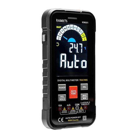
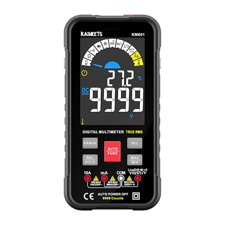
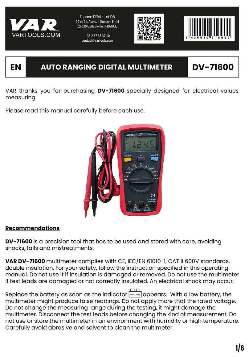
Kaiweets KM601s User manual

KAIWEETS
True
RMS
10000
Counts
Smart
Digital
Multimeter
m
User
Manual
Contact
(CRHSFEE
T
omn_}
AXMIN=
avereL
1|
A
iy
oo
-6H80
[TRUE
RS
MKQHZ%
BmAVFCE
s
C€
10000
Counts
A
macoM
ieuT

[Safety
Inform:
The
multimeter
conforms
to
IEC61010-1
CAT.IIl
1000V,
CAT.IV
600V
overvoltage
safety
standards
and
pollution
level
2.
A
warning
identifies
conditions
and
procedures
that
are
dangerous
to
the
user.
EN
AWamIngs:Read
First
To
avoid
possible
electric
shock
or
personal
injury,
please
obey
the
following
instructions:
®
Do
not
test
voltage
beyond
60VDC,
30VAC
RMS,
or
42V
peak.
Or
there
is
a
risk
of
electric
shock.
®
Do
not
measure
voltages
higher
than
the
rated
value
between
terminals
or
between
terminals
and
ground.
®
Check
that the
meter
is
working
properly
by
measuring
a
known
voltage,
and
do
not
use
it
again
if it
is
not
normal
or
has
been
damaged.
@
Before
using
the
meter,
check
the
meter
case
for
cracks
or
damaged
plastic
parts,
and
if
so,
do
not
use
it
again.
®
The
meter
should
only
be
used
with
the
meter
pen
provided
to
comply
with
the
safety
standards.
®
Before
using
the
meter,
check
the
test
leads
for
cracks
or
damage.
If
so,
replace
it
with
the
same
type
and
electrical
specifications.
When
using
the
meter,
hold
your
fingers
behind
the
1

finger
guard
of
the
probe.
Use
the
meter
according
to
the
measurement
category,
voltage,
or
current
rating
specified
in
the
meter
or
manual.
Observe
local
and
national
safety
policies.
Wear
protective
equipment
(such
as
approved
rubber
gloves,
masks,
and
flame-retardant
clothing)
to
prevent
injury
from
electric
shock
when
dangerous
live
conductors
are
exposed.
When
the
low-voltage
indicator
appears,
replace
the
battery
promptly
to
prevent
measurement
errors.
Do
not
use
the
meter
around
explosive
gases,
vapors,
or
in a
humid
environment.
Remove
the
meter
pen
from
the
meter
before
opening
the
case
or
battery
cover.
Never
use
the
meter
with
the
meter
disassembled
or
the
battery
cover
open.

a
Charge
Jack
b.
NCV
Sensor
<
Power
Button
d
Alarm
Indication
Light
&
LCD
Display
(colorful)
f.
Function
Buttons
g
AJack
h
mA
Jack
i
COM
Jack
J
INPUT
Jack
k
Flashlight

rod
Descriptio
Safety
symbol
meaning
Symbols
Description
Symbols
Description
A
WARNING.
RISK
OF
DANGER.
A
WARNING.RISK
OF
ELECTRIC
SHOCK.
4
Hazardous
Voltage
Ce
Conforms
to
European
Union
directives
Suitable
for
testing
circuits
directly
connected
to
power
points
(sockets
and
power
installations
in
buildings.
CATIl
ave
D *
similarities)
of
low
voltage
power
installations.
caTm
|
Suitable
for
measuring
circuits
connected
to
the
distribution
part
of
low
voltage
power
supply
devices
in
building.
CaATIv
|
Suitable
for
measuring
circuits
connected
to
the
power
supply
of
low
voltage

Function
Buttons
Button
Function
O
Press
and
hold
the
button
for
about
2
seconds
to
turn
on/off
the
meter.
Power
on
is
in
SMART
mode
by
default.
Press
the
button
to
manual
mode.
Then
press again
to
switch
measurement
modes;
Press
and
hold
the
key
for
about
2
seconds
to
return
to
the
SMART(Auto)
mode.
In
SMART
Mode,
the
‘AUTO’
signal
will
display
on the
screen,
and
the
top
left
corner
will
display
‘SMART".
Press
button
to
select
functions.
Press
button
more
than
2
seconds
to
tum
on/off
the
flashlight.
Only
valid
for
voltage,
current
and
live
test.
Press
button
once
to
manual
range
mode.
Press
and
hold
the
button
for
about
2
seconds
to
retum
to
auto-ranging.
This
function
is
invalid
in
SMART
mode.
Only
valid
for
voltage,
resistance
and
mA
test.

MAX
MIN
28
Press
the
button
to
capture
maximum/minimum
value
in
manual
mode.
Press
and
hold
the
key
for
about
2
seconds
to
return
to
normal
measurement.
This
function
is
invalid
in
capacitance,
frequency/duty
ratio,
temperature,
NCV/Live
test.
In
maximum/minimum
measurement,
the
meter
will
enter
the
manual
range
mode.
HOLD
REL
Press
once
to
turn
on/off
data
holding.
Press
for
about
2
seconds
to
turn
on/off
Relative
Value
measurement.
Data
hold
function
is
invalid
in
NCV/Live
test.
Relative
Value
measurement
is
Only
valid
for
voltage,
current and
capacitance.
In
Relative
value
measurement,
the
meter
will
enter
the
manual
range
mode.

Display
Symbol
|
Description
Symbol
Description
‘Symbol
Description
V
Voltage
A
Current
G
Low
Battery
AC(Alternating
DC(Direct
s
Double Insulat
Curent) Curent)
[
|
oouble
nvites
P}
|
piode
Test
2
|
carn
QQ
|
Resistance
Test
Capacitance
Live
Wire
Non-contact
-Ie
Test
Detection
Nev
Voltage
Detection
=
Fuse
=
Damaged
Fuse
|
MANUAL
|
Manual
Mode
o/
|
Frequency/Duty
|
o
)
Audible
Mod
Hz
A’
Ratio
')
Continuity
Test
T
|
Sma
ode

Terminals
Introduction
a.
Jack
indication
light
When
switching
to
other
functions
the
light
above
the
corresponding
jack
will
flash
for
users
to
insert the
right
test
leads
to
the
right
jack.
b.
Input
terminal
for
measuring
ac
and
dc
current
to
10A.
c.
Input
terminal
for
measuring
ac
and
dc
current
to
630mA.
d.
Common
(return)
terminal
for
all
measurements.
&.
Input
terminal
for
measuring
other
functions,
like
voltage,
continuity,
resistance,
capacitance,
frequency
and
testing
diodes.

Warning
1.
Do
not
measure
voltages
higher
than
DG1000V
or
AC750V,
which
can
damage
the
meter
2.
Pay
attention
to
safety
when
measuring
high
voltage
to
avoid
electric
shock
or
personal
injury
3.
Before
use,
test
the
known
voltage
or
current
with
the
meter
to
make
sure
the
meter
is
in
good
function
SMART
(AUTO)
Measurement
Mode
The
Meter
defaults
to
SMART
mode.
In
the
SMART
mode,
the
meter
can
test
DC
voltage,
AC
voltage,
resistance,
continuity,
it
selects
the
range
with
the
best
resolution
automatically.
Turn
on
&
Ready
to
use
1.
Long
press
the
(/)
button
for
about
2
seconds
to
turn
on the
meter,
‘Auka’
will
be
displayed
on the
screen, and
the
pointer
will
swing
by
itself,
indicating
the
SMART
mode.
2.
Insert
the
red
probe
into
‘INPUT’
jack
and
the
black
probe
into
the
‘COM’
jack.
3.
Make
the
red
test
lead
and
the
black
test
lead
touch
each
other
to
check
whether
they
are
normal.
The
buzzer
will
beep
and
the
indicator
light
will
be on
if
normal.
Use
the
continuity
function
as
a
fast,
convenient
method
to
check
for
opens
and
shorts.
9

Smart
mode
Connect
the
test
leads
with
both
ends
of
the
circuit
or
resistance,
the
Meter
automatically
selects
measurement
based
on
the
input.
NOTE:
1.
When
measuring
AC
voltage,
the
frequency
will
be
displayed,
and
when
measuring
other
settings,
the
ambient
temperature
will
be
displayed
on
the
screen.
2.
When
measuring
resistance,
if
the
resistance
value
is
less
than
500Q,
the
meter
will
beep
and
the
indicator
will
light
up.
3.
The
minimum
measurable
voltage
in
SMART
mode
is
0.5V
AC;
0.8V
DC.
MANUAL
Measurement
Mode
The
Meter
defaults
to
SMART
mode.
In
the
SMART
mode,
press
the
‘%’
button
to
switch
to
manual
mode
and
select
function.
AC/DC
voltage
measurement
1.
Press
the
‘A%
bytton
to
*
37
gear,
‘DS
signal
and
‘V"
signal
will
be
displayed
on
the
screen,
indicating
DC
voltage
measurement.
2.
Pressthe
*
button,
signal
<
AC”
and
signal
V"’
will
be
displayed
on
the
screen,
indicating
AC
voltage
measurement.
10

3.
Insert the red
probe
into
‘INPUT®
jack
and
the
black
probe
into
the
‘COM’
jack.
4.
Touch
the
meter
probe
to
both
ends
of
the
power
supply
under
test.
5.
When
measuring
AC
voltage,
the
frequency
is
displayed
at
the
same
time
otherwise
the
ambient
temperature
is
displayed.
6.
Read
the
measurement
results
from
the
display.
NOTE:
1.
When
measuring
AC
voltage,
the
frequency
will
be
displayed.
2.
When
measuring
DC
voltage,
the
ambient
temperature
will
be
displayed
on
the
screen.
3.
Do
not
use
the
AC
voltage
test
function
to
test
DC
voltage
and
vice
versa.
4.
Do
not
measure
voltage
exceeding
1000V
DC
or
750V
AC
to
avoid
damage
to
the
meter.
Resistance
measurement
1.
Press
‘A9
button
to
select
‘2
gear.
¢
Q
signal
will
be
displayed
on
the
screen,
indicating
the
resistance
measurement.
2.
Insert the red
probe
into
‘INPUT’
jack
and
the
black
probe
into
the
‘COM’
jack.
3.
Touch
the
meter
probe
to
both
ends
of
the
resistance
under
test.
4.
Read
the
measurement
results
from
the
display.
NOTE:
1.
Do
not
change
the
resistance
while
taking
measurements.
2.
Do
not
test
parallel
circuits.
The
accuracy
of
the
measurement
will
be
affected,
and
the
results
1

may
not
be
accurate.
3.
Do
not
directly
measure
the
interal
resistance
of
micrometers,
galvanometers,
batteries,
and
other
instruments.
Continuity
test
1.
Press ‘fune’
button
to
©)
*
gear,
indicating
the
continuity
measurement.
2.
Connect
the
test
leads
to
both
ends
of
the
circuit
under
test.
3.
Insert the red
probe
into
“INPUT"
jack
and
the
black
probe
into
the
‘COM’
jack.
4.
Contact
the
probe
with
both
ends
of
the
measured
resistance
or
circuit.
5.
When
the
resistance
value
is
less
than
about
500,
the
buzzer
sounds.
6.
Read
the
measurement
results
from
the
display.
NOTE:
If
the
resistance
of
the circuit
or
resistor
under
test
is
less
than
500
and
the
circuit
is
on
position,
the
buzzer
will
beep
and
an
indicator
light
will
light
up,
and
the
screen
will
display
the
measured
resistance
value.
Diode
test
1.
Press
‘AR’
button
to
‘PF
gear,
indicating
the
diode
testing.
2.
Insert the red
probe
into
‘INPUT’
jack
and
the
black
probe
into
the
‘COM’
jack.
3.
Connect
red
test
lead with
the
positive
polarity
of
the
diode,
black
test
lead
with
the
negative
polarity.
4.
If
the
test
leads
are
connected
reversely
with
the
diode
polarity,
‘f}}’
will
be
displayed
on
the
screen.
5.
Read
the
measurement
results
from
the
display.
12

Good
Diode(There
will
be
two
situations)
When
the
meter
probe
is
properly
connected:
—
1/
%+
Forward
Bias
When
the
meter
probe
is
incorrectly
connected:
l/
%"
v
,
=
Reverse
Bias
Bad
Diode{(There
will
be
two
situstions)
5,
When
the
meter
probe
is
properly
connected:
_
l/
/
.
/EA
=
¥
>
Open
13

When
the
meter
probe
is
incorrectly
connected:
~
__
l/
.
Capacitance
measurement
1.
Press
“fue’
button
to
“IF
gear,
‘nF’
signal
will
be
displayed
on the
screen,
indicating
capacitance
testing.
2.
Insert the red
probe
into
‘INPUT’
jack
and
the
black
probe
into
the
‘COM’
jack.
3.
Touch
the
meter
probe
to
both
ends
of
the
capacitor
under
test.
4.
Read
the
measurement
results
from
the
display.
NOTE:
1.
If
the
measured
value
is
significantly
different
from
the
value
marked
on
the
capacitor,
the
capacitor
is
damaged.
2.
Before
measuring
the
capacitor,
discharge
the
capacitor
to
avoid
damage
to
the
Meter.
Do
so
by
connecting
the
capacitor
to
a
high-powered
resistor.
3.
Discharge
the
capacitor
after
measurement
to
avoid any
potential
safety
hazards.
4.
If
the
capacitance
is
large,
it
may
take
a
long
time
for
the
reading
to
stabilize.
14

AC/DC
mV
voltage
measurement
1.
Press
the
“Fme’
button
to
‘mV"
setting,
‘RS
signal
and
‘mV’
signal
will
be
displayed
on
the
screen,
indicating
DC
mV
voltage
measurement.
2.
Press
the
[2=]
button,
‘AC’signal
and
‘mV’
signal
will
be
displayed
on
the
screen,
indicating
AC
mV
voltage
Tigasurement.
3.
Insert the red
probe
into
‘INPUT’
jack
and
the
black
probe
into
the
‘COM’
jack.
4.
Touch
the
probe
with
both
ends
of
the
measured
power
supply.
5.
When
measuring
AC
voltage,
the
frequency
is
displayed
at
the
same
time;
otherwise,
the
ambient
temperature
is
displayed.
6.
Read
the
results
from
the
display.
NOTE:
1.
When
measuring
AC
voltage,
the
frequency
will
be
displayed.
2.
When
measuring
DC
voltage,
the
ambient
temperature
will
be
displayed
on
the
screen.
3.
Do
not
use
the
AC
voltage
test
function
to
test
DC
voltage
and
vice
versa.
4.
Do
not
measure
voltage
exceeding
1000V
DC
or
750V
AC
to
avoid
damage
to
the
meter.
Frequency/Duty
measurement
1.
Press
the
“Ame’
button
to
‘Hz%’
setting,
‘Hz’
signal
and
‘%’
signal
will
be
displayed
on
the
screen,
indicating
Frequency/Duty
Ratio
testing.
2.
Insert the red
probe
into
‘INPUT’
jack
and
the
black
probe
into
the
‘COM’
jack.
3.
Touch
the
probe
with
both
ends
of
the
measured
power
supply.
15

4.
Read
the
results
from
the
display.
Temperature
measurement
1.
Insert the
positive
pole
of
the
K~type
thermocouple
into
the ‘Input’
jack
and
the
negative
pole
into
the
‘COM’
jack.
2.
Press
the
‘4412
button
to
‘
/¥
’,
*
'€’
signal
and
‘
°F
signal
will
be
displayed
on
the
screen,
indicating
temperature
testing.
3.
Touch
the
end
of
the
K-Type
thermocouple
to
the
object
being
measured.
The reading
may
take
few
seconds
to
be
stable.
NOTE:
When
the
K-Type
thermocouple
does
not
in
contact
with
the
object
under
test,
it
will
read
the
ambient
temperature.
Non-contact
AC
voltage
detection
1.
Press
the
‘A%
ptton
to
‘
Mee
*
setting,
‘NCV’
signal
will
be
displayed
on the
screen,
indicating
the
NCV
testing.
2.
Place
the
NCV
probe
closer
to
the
point
to
be
tested
gradually.
3.
When
the
indicator
glows
and
the
unit
beeps,
you
know
there’s
voltage
present.
16

When
the
Meter
detects
a
weak
signal, the
green
indicator
will
light
up,
the
buzzer
will
beep
in
a
slow
tone,
and
‘
—-L
"
will
be
displayed
on the
screen.
When
the
meter
detects
a
strong
signal, the
red
indicator
will
light
up,
the
buzzer
will
beep
in
a
fast
tone,
and
*
~-H
"
will
be
displayed
on
the
screen
Live
wire
detecting
1.
Press
the
“Ame’
button
to
‘
tiee
*
setting,
NGV’
signal
will
be
displayed
on the
screen.
2.
Press
the
‘(%]
button
to
display
the
‘LIVE’
symbol.
Insert
the
red
probe
into
the
‘INPUT’
jack
and
remove
the
black
probe.
3.
Touch
the
object
under
test
with
the
red
test
lead
point.
NOTE:
1.
When
the
indicator
light
lights
up
that
means
the
measured
position
for
the
fire
line,
please
be
carefull
2.
When
the
Meter
detects
a
weak
signal, the
green
indicator
will
light
up,
the
buzzer
will
beep
in
a
slow
tone,
and
*
L’
will
be
displayed
on the
screen.
This
means
the
test
leads
may
not be
fully
connected
to
the
socket,
please
test
again
after
full
connection.
3.
When
the
meter
detects
a
strong
signal,
the red
indicator
will
light
up,
the
buzzer
will
beep
in
a
fast
tone,
and
‘
==H
*
will
be
displayed
on
the
screen.
17

Ampere
(A)
current
measurement
1.
Insert the red
probe
into
the
‘A’
jack
and
the
black
probe
into
the
‘COM’
jack.
The
Meter
will
automatically
adjust
to
the
‘A’
gear.
‘DC’
signal
and
‘A’
signal
will
be
displayed
on the
screen,
indicating
DC
current
measurement.
2.
Press
the
‘%]
button,
‘A’
signal
and
‘AC’
signal
will
be
displayed
on
the
screen,
indicating
of
AC
current
measurement.
NOTE:
1.
When
measuring
AC
current,
the
frequency
will
be
displayed,
and
when
measuring
DC
current,
the
ambient
temperature
will
be
displayed
on
the
screen.
2.
‘LEAD’
signal
will
be
displayed
on
the
screen
and
the
indicator
light
will
turn
red
when
the
test
leads
are
connected
incorrectly,
please
insert the
red
test
lead
into
‘A’
jack.
3.
The
meter
will
turn on the
current
testing
function
when
you
insert the
red
test
lead
into
‘A’
Jack
and
the
black
test
lead
into
‘COM
jack
in
any
mode.
For
safety,
users
cannot
press
the
“Ame”
button
to
switch
the
functions.
4.
The
meter
will
beep
regularly
to
remind
users
to
use
the
current
testing
function
correctly.
Do
not
measure
current
>10A
in
this
gear,
in
case
of
the
10A
fuse
burnt.
mA
current
measurement
1.
Insert the
red
probe
into
the
‘mA’
jack
and
the
black
probe
into
the
‘COM’
jack.
The
meter
will
automatically
adjust
to
the
A’
gear.
‘DC’
signal
and
‘mA’
signal
will
be
displayed
on the
screen,
18

indicating
DC
current
measurement.
2.
Press
the
‘(5]
button,
‘mA’
signal
and
‘AC’
signal
will
be
displayed
on
the
screen,
indicating
of
AC
current
measurement.
NOTE:
1.
When
measuring
AC
current,
the
frequency
will
be
displayed,
and
when
measuring
DC
current,
the
ambient
temperature
will
be
displayed
on
the
screen.
2.
‘LEAD’
signal
will
be
displayed
on
the
screen
and
the
indicator
light
will
turn
red
when
the
test
leads
are
connected
incorrectly,
please
insert the
red
test
lead
into
‘mA’
jack.
3.
The
meter
will
turn
on
the
current
testing
function
when
you
insert
red
test
lead
into
‘mA"’
jack
and
black
test
lead
into
‘COM’
jack
in
any
mode.
For safety,
users
cannot
press
the
‘e’
button
to
switch
the
functions.
4.
The
meter
will
beep
regularly
to
remind
users
to
use
the
current
testing
function
correctly.
Do
not
measure
current
>
630mA
in
this
gear,
in
case
of
the
mA
fuse
burnt.
19
Table of contents
Other Kaiweets Multimeter manuals

Kaiweets
Kaiweets ST600X User manual

Kaiweets
Kaiweets ST500Y User manual

Kaiweets
Kaiweets KM100 User manual
Kaiweets
Kaiweets KM601 User manual

Kaiweets
Kaiweets KM100 User manual

Kaiweets
Kaiweets KM602 User manual

Kaiweets
Kaiweets KM201 User manual
Kaiweets
Kaiweets HT118A User manual
Kaiweets
Kaiweets KM312AB User manual
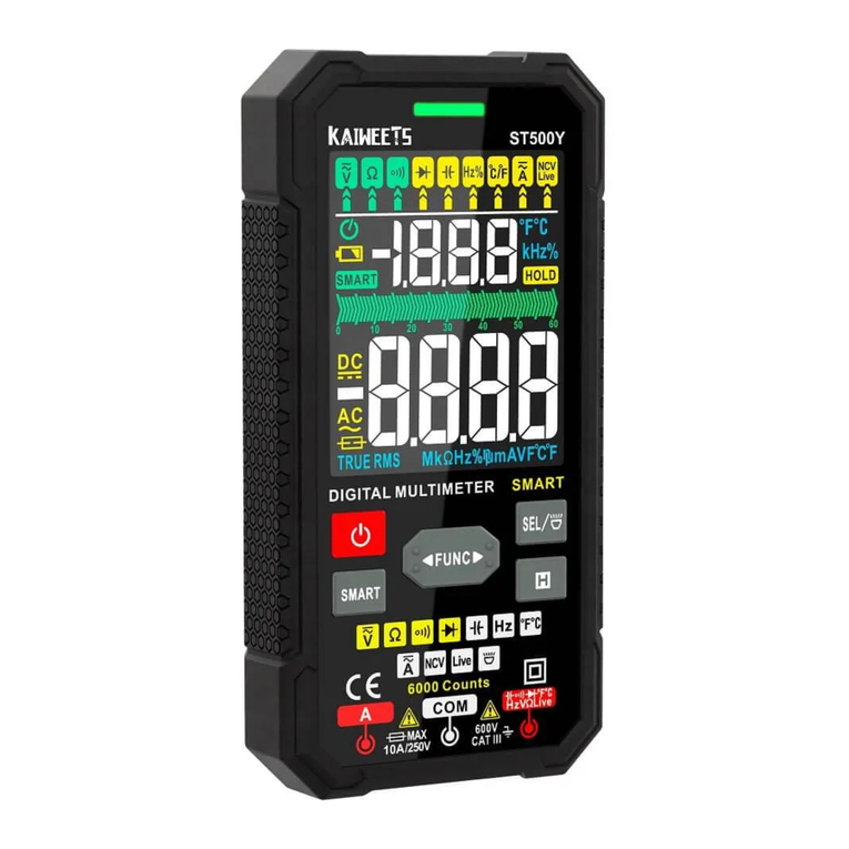
Kaiweets
Kaiweets HT118A User manual
Popular Multimeter manuals by other brands

Keysight Technologies
Keysight Technologies 34450A Quick start up guide

Testboy
Testboy TB 312 operating instructions

Fieldpiece
Fieldpiece HB74 Heavy Duty Operator's manual

Harbor Freight Tools
Harbor Freight Tools 40994 operating instructions

Chauvin Arnoux
Chauvin Arnoux F403 Start guide

Emos
Emos MD-410 manual