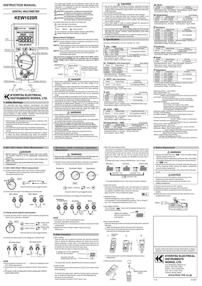
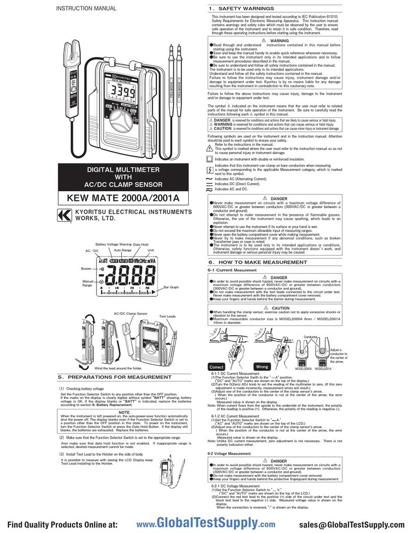
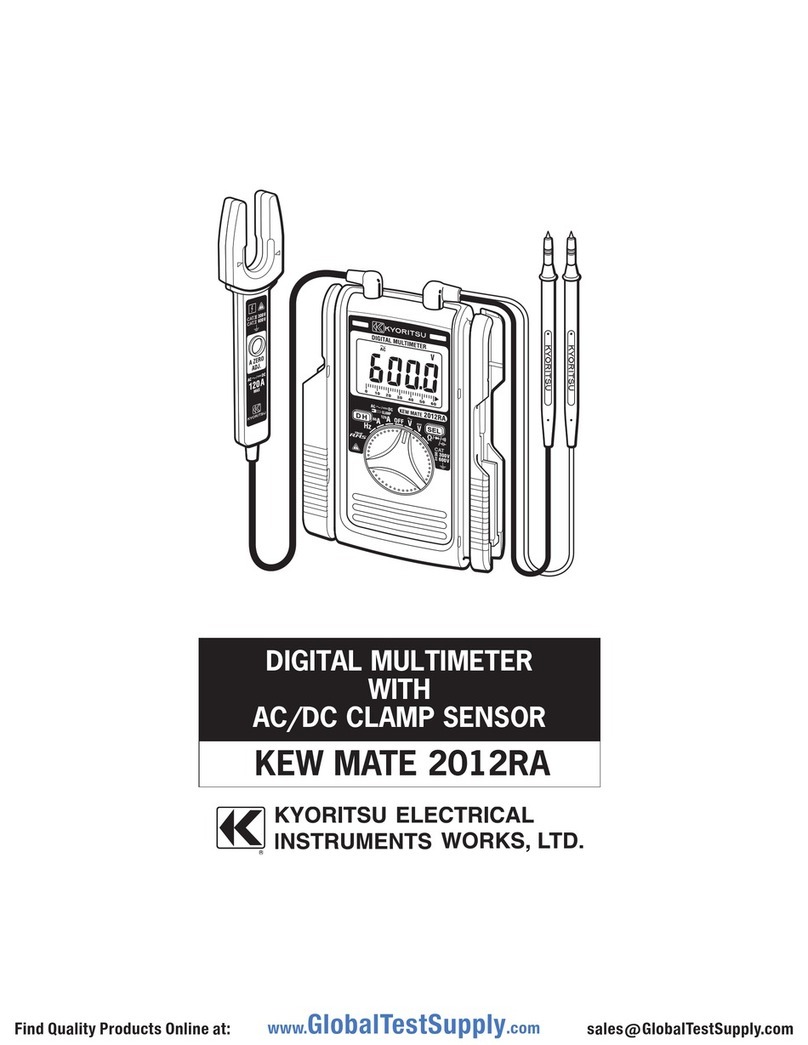
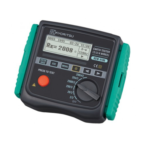
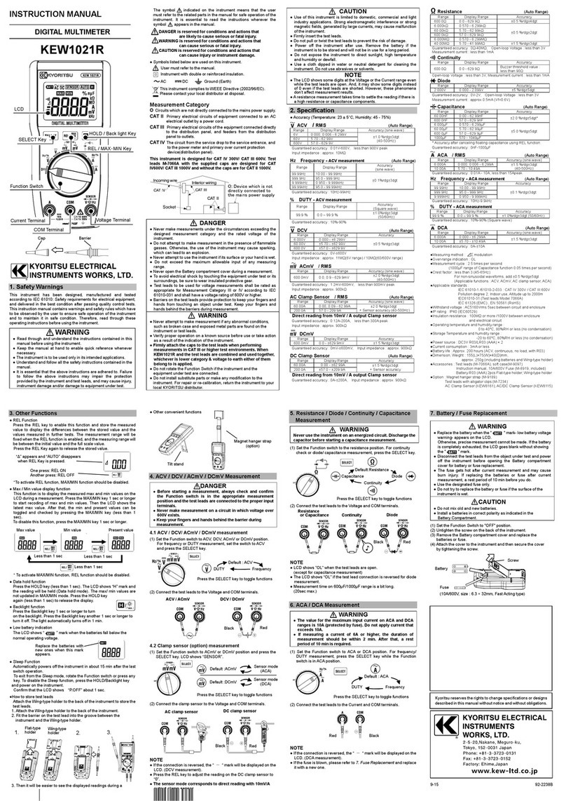
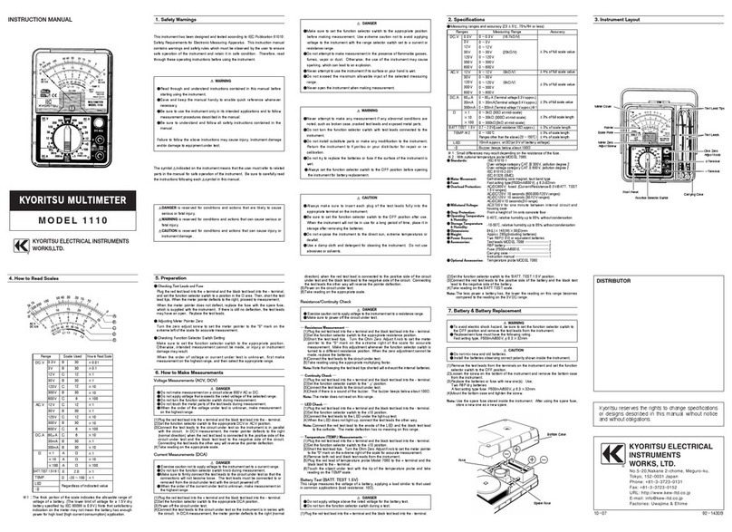
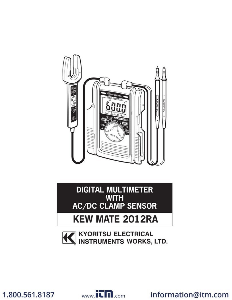
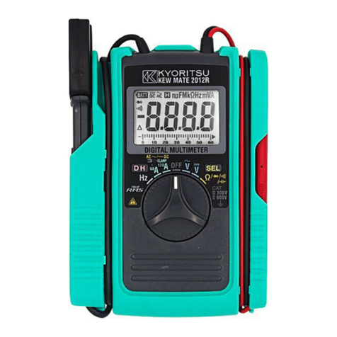
KYORITSU KEW 1018 User manual

1.SafetyWarnings
This instrument has been designed, manufactured and
testedaccordingtothefollowingstandards.
IEC61010-1MeasurementCATⅢ300VPollutiondegree2
IEC61010-031
IEC61326
Thisinstructionmanualcontainswarningsandsafety
ruleswhichmustbeobservedbytheuserto ensure
safeoperation of theinstrumentandretainit in safe
condition.Therefore,readthroughtheseoperating
instructionsbeforeusingtheinstrument.
WARNING
●Read through and understand instructions
containedinthis manual before startingusingthe
instrument.
●Saveand keep the manual handy to enable quick
referencewhenevernecessary.
●Thisinstrumentshouldonlybeusedby suitably
trainedpersonandbesureto follow measurement
proceduresdescribedinthemanual.Kyoritsu
assumesno responsibility fordamageandinjury
causedbymisuseornotfollowinginstructionsinthe
manual.
●Besure tounderstandandfollow allsafety
instructionscontainedinthemanual.
Besuretoobservetheaboveinstructions.
Failuretofollowthe aboveinstructionsmaycause
injury, instrument damage and/or damage to
equipmentundertest.
Thesymbol indicatedontheinstrumentmeansthatthe
usermust refertorelatedpartsin themanualforsafe
operationoftheinstrument.
Besuretocarefullyreadtheinstructionsfollowing each
symbolinthemanual.
DANGER isreserved for conditions and actions
thatarelikelytocauseseriousorfatalinjury.
WARNING isreservedforconditionsandactions
thatcancauseseriousorfatalinjury.
CAUTION is reserved for conditions and actions
thatcancauseinjuryorinstrumentdamage.
DANGER
●Nevermakemeasurementonthecircuitinwhich
electricalpotential to ground over 300V AC/DC
exists.
●Donotattempttomakemeasurementinthe
presenceofflammablegasses.Otherwise, the
useoftheinstrumentmaycausesparking,which
canleadtoanexplosion.
●Besureto keep your fingers behind the Finger
barrierpartoftestlead.
●Neverattempttousetheinstrumentifitssurface
oryourhandiswet.
●Donot open the instrument casewhenmaking
measurement.
WARNING
●Neverattempt to make any measurementif any
abnormalconditions are noted, such as broken
case,crackedtestleadsandexposedmetalparts.
●Do not turn the function selector switch with test
leadsconnectedtotheinstrument.
●Donotinstallsubstitutepartsormakeany
modificationtotheinstrument.
●Donottrytoreplacethebatteriesifthesurfaceof
theinstrumentiswet.
●Makesuretodisconnecttestleadsfromthe
deviceundertestwhenopeningthecasefor
batteryreplacement.
CAUTION
●Alwaysmakesureto checkFunctionswitch is
settingto the appropriaterangebeforestarting
measurement.
●Donotexposetheinstrument to the direct sun,
hightemperatureandhumidityordewfall.
●Whentheinstrumentwillnotebeinuseforalong
period,placeitinstorageafterremovingthe
batteries.
●Usea cloth dippedin water or neutral detergent
forcleaningtheinstrument.Donotuseabrasives
orsolvents.
Pleaserefertofollowingexplanationofthesymbols
markedontheinstrumentorinthemanual.
●Symbols
:
Ground
:
AC
:
DC
:
ACandDC
Ω:
Resistance
:
Diode
:
Buzzer
:
Capacitor
Hz:
Frequency
F:
Doubleorreinforcedinsulation
●
Measurement
CATⅡ:
Primaryelectricalcircuitofequipment
withpowercordforconnectiontooutlet.
CATⅢ:
Primary electrical circuit of the
equipment,whichissuppliedpowerfrom
adistributionboard,andcablerunfroma
distributionboardtoanoutlet.
2.Features
ThisisaDigitalMultiMeterprovidingmostportabilityby
meansofstowingtheinstrumentbodytogetherwith
probeinthenotebook-sizecover.
●Designedtointernationalsafetystandards.
IEC61010-1MeasurementCAT.Ⅲ300V
Pollutiondegree2
IEC61010-031
(probeassemblies)
●RELfunction to check thedifferenceofmeasured
values
●Autopowerofffunctiontosavebatteryconsumption
●Dataholdfunction
●DiodeandContinuitycheckfunction
●Auto-rangingfunction
●Frequencymeasurementfunction
●DUTYmeasurementfunction
(ExpressPulsewidth/Pulseperiodasapercentage)
3.Specification
●Measuringrangesandaccuracy
(23±5℃,underthe45%〜75%RH)
DCVFunction(5Autoranging):Inputimpedanceapprox.10MΩ
ACVFunction(4Autoranging):Inputimpedanceapprox.10MΩ
ResistanceFunction(6Autoranging)
Diodecheck/ContinuitycheckFunction
CapacityFunction(6Autoranging)
Frequency(6Autoranging)/DUTYFunction
Range
400mV
4V
40V
400V
600V
Measuringrange
0〜600V
Accuracy
±0.8%rdg±5dgt
±1.0%rdg±5dgt
Range
4V
40V
400V
600V
Measuringrange
0〜600V
Accuracy
±1.3%rdg±5dgt(50/60Hz)
±1.7%rdg±5dgt(〜400Hz)
±1.6%rdg±5dgt(50/60Hz)
±2.0%rdg±5dgt(〜400Hz)
Range
400Ω
4kΩ
40kΩ
400kΩ
4MΩ
40MΩ
Measuringrange
0〜40MΩ
Accuracy
±1.0%rdg±5dgt
±2.5%rdg±5dgt
Range
4nF
40nF
400nF
4uF
40uF
200uF
Measuringrange
〜200uF
Accuracy
±5.5%rdg±10dgt
±3.5%rdg±10dgt
±3.5%rdg±5dgt
±4.5%rdg±5dgt
Range
10Hz
100Hz
1000Hz
10kHz
100kHz
200kHz
DUTY
Measuringrange
〜200kHz
Inputsensitivity:
morethan1.5V(RMS)
Accuracy
±0.1%rdg±5dgt
0.1〜99.9%
(Pulsewidth/Pulseperiod)
±2.5%rdg±5dgt
Function
Diodecheck
Continuitycheck
Measuringrange
Testcurrentapprox.0.4mA
Buzzerbeepsbelowabout120Ω
Note:
*AtVoltagefunction,theAuto-rangingfunctionisreleased
bypressingtheSELECTkey.Tomeasureavoltage
again,turntheFunctionswitchtothe"OFF"position
once.ThensetittotheVoltagefunctionagain.
●Standards:
IEC61010-1 MeasurementCATⅢ300V,pollutiondegree2
MeasurementCATⅡ600V,pollutiondegree2
IEC61010-031
IEC61326
●Methodofoperation:△∑method
●Indication:
LCDmaximumvalue3999(ACV,DCV,Ω,F)
units,symbols
●Overrangedisplay:
"OL"symbolisdisplayedontheLCD.
Incasethatthevalueisbeyondeffectivemeasuring
rangeat the position ofΩ function range and manual
range.
●Auto-ranging:
Rangeshiftstoupperrangewhenindicatedvalueis
morethan3999.Rangeshiftstolowerrangewhen
indicatedvalueislessthan360.
●Samplingrate: approx.400ms
●OperatingEnvironmentalconditions
−indooruse
−altitudeupto2000m
●
Temperature&Humidityrange(guaranteedaccuracy):
23℃±5℃ Relativehumidity:lessthan75%
●OperatingTemperature&Humidityrange:
0℃〜+40℃ Relativehumidity:lessthan80%
●StorageTemperature&Humidityrange:
-20℃〜+60℃ Relativehumidity:lessthan70%
●InsulationResistance:
Itshouldbemorethan10MΩ/DC1000Vbetween
electricalcircuitandenclosures.
●WithstandVoltage:
ItshouldbemorethanAC3700V/foroneminute
betweenelectricalcircuitandenclosures.
●OverloadProtection:
Voltagefunction: 720V(RMS.)10seconds
Resistancefunction: 250V(RMS.)10seconds
Diode/Continuity: 250V(RMS.)10seconds
Capacityfunction: 250V(RMS.)10seconds
Frequencyfunction:250V(RMS.)10seconds
●Dimensions: approx.107(L)x54(W)x10(D)mm
●Weight: approx.70g(includingbatteries)
●Powersource: TwoLR44(SR44)1.5Vorequivalent
●Accessories: TwoLR44(SR44)batteries
Portableholder
Instructionmanual
CAUTION
Thevoltageshownaboveisthe overloadprotection
(overvoltageprotection)fortheinstrument.
Makesurenottoexceedthevalueofvoltageshown
above.
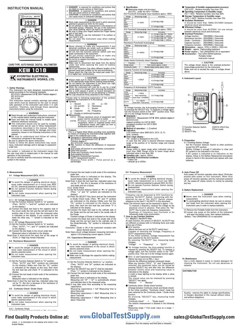
4.InstrumentLayout
①FunctionSelectorSwitch ④DATAHOLDKey
②Display ⑤TestLeads
③SELECTKey
5.Preparation
5-1CheckingBatteryVoltage
SettheFunctionSelectorSwitchtootherpositions
excepttheOFFposition.
BatteryVoltageisenoughifindicationisclearandBT
symbolisnotindicatedinthisbout.
IfBTsymbolisindicatedornoindicationonthe
display,followtotheBatteryReplacementprocedures
showninitem9inthisdocumentandreplacewithnew
batteries.
INSTRUCTIONMANUAL
6.Measurements
6-1VoltageMeasurement(DCV,ACV)
DANGER
●Toavoidthedangerofgettingelectricalshock,
nevermakemeasurementonacircuitover600V
AC/DC.(electricalpotentialtoground300VAC/DC)
●DonotoperateFunctionSelectorSwitchduring
measurement.
●Donotmakemeasurementwhenopeningthe
instrumentcase.
6-1-1DCVoltageMeasurement(DCV)
(1)SettheFunctionSelectorSwitchto" "position.
(Then, "AUTO"," "and"mV" symbols are indicated
onthedisplay.)
(2)Connectthe black test lead to the negative side of
thecircuitunderthetestandtheredtestleadtothe
positivesideofthecircuit,thenthemeasuredvalue
isindicatedonthe display. If you connect thetest
leadstheother way, "
-
"symbolis indicated on the
display.
6-1-2ACVoltageMeasurement(ACV)
(1)SettheFunctionSelectorSwitchto" "position.
(Then,"AUTO"," ",and"V"symbolsareindicated
onthedisplay.)
(2)Connectthetestleadstothecircuitundertest.
Measuredvalueisindicatedonthedisplay.
Note)Evenif short-circuit theinputlineattherange of
AC4V,2〜5dgtmayremainindicated.
6-2ResistanceMeasurement
DANGER
●Toavoidthedangerofgettingelectricalshock,
nevermake measurementofthecircuit inwhich
electricpotentialexists.
●Donotmakemeasurementwhenopeningthe
instrumentcase.
(1)SettheFunctionSelectorSwitchto"Ω"position.
(Then,"AUTO"and"MΩ"symbolsareindicatedon
thedisplay.)Makesurethatthe"OL"symbolis
indicatedon the display at thisbout, then short the
testleadtipsandcheck"0"isindicatedonthe
display.
(2)Connectthetestleadstobothendsoftheresistance
undertest.
Measuredvalueisindicatedonthedisplay.
Note)Evenifshortthetestleadtips,indicatedvaluemay
notbe "0". But this isbecause of the resistanceof
testleadsandnotafailure.
6-3ContinuityCheck/DiodeCheck
DANGER
●Toavoidthedangerofgettingelectricalshock,
nevermake measurementofthecircuit inwhich
electricpotentialexists.
●Donotmakemeasurementwhenopeningthe
instrumentcase.
6-3-1ContinuityCheck
(1)SettheFunctionSelectorSwitchto" / "position.
(Then," "and Ω symbols are indicated on the
display.)
(2)Makesure that the"OL"symbol is indicated on the
displayatthisbout,thenshortthetestleadtipsand
check"0"isindicatedonthedisplayandcheckifthe
buzzerbeeps.
(3)Connectthetestleadstobothendsoftheresistance
undertest.
Measuredvalueisindicatedonthedisplay.The
buzzerbeepsbelowabout120Ω.
Note)Evenifshortthetestleadtips,indicatedvaluemay
notbe "0". But this isbecause of the resistanceof
testleadsandnotafailure.
6-3-2DiodeCheck
(1)SettheFunctionSelectorSwitchto" / "position.
(Then," "and"Ω"symbolsareindicatedonthe
display.)
(2)PresstheSELECTKeytwiceandsettheinstrument
toDiodeCheckmode.(Then," "and"V"
symbolsare indicated onthedisplay.)Makesure
thatthe "OL" symbol is indicatedon the display at
thisbout,thenshortthetestleadtipsandcheck"0"
isindicatedonthedisplay.
(3)Connectthe black testlead to the cathode sideof
theDiodeandtheredtestleadtotheanodesideof
theDiode.
ForwardvoltageofDiodeisindicatedonthedisplay.
(4)Connecttheblacktestleadtotheanodesideofthe
Diodeandtheredtestleadtothecathodesideofthe
Diode.Normally,"OL"symbolisindicatedonthe
display.
Conclusion:Diodeis OK if the instrument complieswith
aboveitems(3)and(4).
Note)Open-circuitvoltagebetweenmeasuringterminalsis
approx.1.5V.(measuringcurrentapprox.0.4mA)
6-4CapacitanceMeasurement
DANGER
●Toavoidthedangerofgettingelectricalshock,
nevermake measurementofthecircuit inwhich
electricpotentialexists.
●Donotmakemeasurementwhenopeningthe
instrumentcase.
●Makesuretodischargethecapacitorbeforemaking
measurement.
(1)SettheFunctionSelectorSwitchto" "position.
(Then,"AUTO"and "nF" symbols are indicatedon
thedisplay.)
(2)PresstheSELECTkeyand"0"shallbeindicated.
(Then,"△"symbolisindicatedonthedisplay.)
(3)Connectthetestleadstobothendsoftheresistance
undertest.
Measuredvalueisindicatedonthedisplay.
Measuringunit"nF" / "uF" is automatically chosen
andindicatedduetothemeasuredvalue.
Note)Itmay take some time according to the measuring
capacitance.
Measuringcapacitance<4uFMeasuringtimeis
about2seconds
Measuringcapacitance < 40uF Measuringtimeis
about7seconds
Measuringcapacitance < 100uF Measuringtime is
about15seconds
6-5FrequencyMeasurement
DANGER
●Toavoid the dangerofgettingelectrical shocks,
nevermakemeasurementonacircuitover300V
AC/DC.(electricalpotentialtoground300VAC/DC)
●DonotoperateFunctionSelectorSwitchduring
measurement.
●Donotmakemeasurementwhenopeningthe
instrumentcase.
FrequencycanbemeasuredatACVfunctionsby
pressing"Hz/DUTY"Switch.Concerningwiththe
directionforuseof"Hz/DUTY"Switch,please
referencetotheitem7-1Hz/DUTYinthisdocument.
Note)Theminimuminput canbemeasuredisapprox.
1.5V.
7.HowtouseFunctionSwitches
7-1SELECT,Hz/DUTYKey
Ateachfunction,theactionsofSELECT,Hz/DUTYkey
aredifferentsopleaserefertofollowingitemsandmake
activeuseofthem.
●ACVfunction
(AbovetwokeysactasHz/DUTYswitchkey.)
CapableofselectingtheVoltage,Frequencyor
DUTYmeasurementmode.
Attheinitialcondition,Voltagemeasurementhas
beenselectedfortheACVfunction.
Bypressing"Hz/DUTY"key,measuringmode
changes.
"Voltage"→ "Frequency"→ "DUTY"
●DCV,Ω andCapacitancemeasurement
(AbovetwokeysactasREL△ key.)
Indicatethedifferencebetweenmeasuredvalues.
Whenany function ("DCV", "Ω" and "Capacitance")
selected,themeasuredvaluecanbestoredby
pressingSELECT key and after that, the difference
betweenstoredvalueandmeasuringvalueis
indicatedonthedisplay
(△markiskeeplightingonthedisplaywhileavalue
isstored)
Thestoredvaluecanbereleasedbypressing
"SELECT"keyagain.
"Release"→ "Memory"
●Continuitycheck/Diodecheckfunction
(ChangebetweenContinuitycheckandDiodecheck)
At the initial condition, "Continuity check" mode has
beenselectedfortheContinuitycheck/Diodecheck
function.
Bypressing "SELECT"key,measuringmode
changes.
"Continuitycheck"→ "Diodecheck"
Therelativemeasurementisallowedinthefollowing
range.
*Measuringrange=Fullscalevalue at a range−
initialvalue
7-2DATAHOLDKey
Themeasuredvaluecanbeholdatallfunctions.
Bypressing "DATA HOLD" key,"DH"symbolindicated
onthedisplayandtheindicatedvaluecanbeheld.
Bypressing"DATAHOLD"keyagain,"DH"symbol
disappearsfromthedisplayandhelddataisreleased.
8.AutoPowerOff
Autopowerofffunctionoperateswhenabout15minutes
passedafterpoweronthisinstrument.WhenAuto
powerofffunctionoperatesandtheinstrumentpowered
off,the power-off statuereturns to normalby pressing
anykey.
9.BatteryReplacement
DANGER
●Neveropentheinstrumentcasewhenmaking
measurement.
●Toavoidgettingelectricalshock,besuretoremove
testleads from the instrumentwhenopeningthe
instrumentcaseinordertoreplacebatteries.
(1)RemovethePortableholderfromtheinstrument.
(2)Loosenone screw on the bottomof the instrument
andopenthebatterycover,thenreplacebatteries.
Battery:TwoLR44(SR44)1.5Vorequivalent
10.Maintenance
Useaclothdipped inwateror neutraldetergentfor
cleaningtheinstrument.Donotuseabrasivesor
solvents.
①
③
②
④
⑤
DISTRIBUTOR
KYORITSUELECTRICAL
INSTRUMENTSWORKS,LTD.
No.5-20,Nakane2
―
chome,Meguro-ku,
Tokyo,152-0031Japan
Phone:81
―
3
―
3723
―
0131
Fax
:81
―
3
―
3723
―
0152
URL:http://www.kew-ltd.co.jp
Factories:Uwajima&Ehime
Kyoritsureservestherightstochangespecifications
orDesignsdescribed in this manual without notice
andwithoutobligations.
CARDTYPEAUTORANGEDIGITALMULTIMETER
KEW1018
KYORITSUELECTRICALINSTRUMENTS
WORKS,LTD.TOKYO,JAPAN
1.SafetyWarnings
This instrument has been designed, manufactured and
testedaccordingtothefollowingstandards.
IEC61010-1MeasurementCATⅢ300VPollutiondegree2
IEC61010-031
IEC61326
Thisinstructionmanualcontainswarningsandsafety
ruleswhich must be observedbytheuserto ensure
safeoperation of theinstrumentandretainit in safe
condition.Therefore,readthroughtheseoperating
instructionsbeforeusingtheinstrument.
WARNING
●Read through and understand instructions
containedinthis manual before startingusingthe
instrument.
●Saveand keep the manual handy to enable quick
referencewhenevernecessary.
●Thisinstrumentshouldonlybeusedby suitably
trainedpersonandbesureto follow measurement
proceduresdescribedinthemanual.Kyoritsu
assumesno responsibility fordamageandinjury
causedbymisuseornotfollowinginstructionsinthe
manual.
●Besure tounderstandandfollow allsafety
instructionscontainedinthemanual.
Besuretoobservetheaboveinstructions.
Failuretofollowthe aboveinstructionsmaycause
injury, instrument damage and/or damage to
equipmentundertest.
Thesymbol indicatedontheinstrumentmeansthatthe
usermust refertorelatedpartsin themanualforsafe
operationoftheinstrument.
Besuretocarefullyreadtheinstructionsfollowing each
symbolinthemanual.
DANGER isreserved for conditions and actions
thatarelikelytocauseseriousorfatalinjury.
WARNING isreservedforconditionsandactions
thatcancauseseriousorfatalinjury.
CAUTION is reserved for conditions and actions
thatcancauseinjuryorinstrumentdamage.
DANGER
●Nevermakemeasurementonthecircuitinwhich
electricalpotential to ground over 300V AC/DC
exists.
●Donotattempttomakemeasurementinthe
presenceofflammablegasses.Otherwise, the
useoftheinstrumentmaycausesparking,which
canleadtoanexplosion.
●Besureto keep your fingers behind the Finger
barrierpartoftestlead.
●Neverattempttousetheinstrumentifitssurface
oryourhandiswet.
●Donot open the instrument casewhenmaking
measurement.
WARNING
●Neverattempt to make any measurementif any
abnormalconditions are noted, such as broken
case,crackedtestleadsandexposedmetalparts.
●Do not turn the function selector switch with test
leadsconnectedtotheinstrument.
●Donotinstallsubstitutepartsormakeany
modificationtotheinstrument.
●Donottrytoreplacethebatteriesifthesurfaceof
theinstrumentiswet.
●Makesuretodisconnecttestleadsfromthe
deviceundertestwhenopeningthecasefor
batteryreplacement.
CAUTION
●Alwaysmakesureto checkFunctionswitch is
settingto the appropriaterangebeforestarting
measurement.
●Donotexposetheinstrument to the direct sun,
hightemperatureandhumidityordewfall.
●Whentheinstrumentwillnotebeinuseforalong
period,placeitinstorageafterremovingthe
batteries.
●Usea cloth dippedin water or neutral detergent
forcleaningtheinstrument.Donotuseabrasives
orsolvents.
Pleaserefertofollowingexplanationofthesymbols
markedontheinstrumentorinthemanual.
●Symbols
:
Ground
:
AC
:
DC
:
ACandDC
Ω:
Resistance
:
Diode
:
Buzzer
:
Capacitor
Hz:
Frequency
F:
Doubleorreinforcedinsulation
●
Measurement
CATⅡ:
Primaryelectricalcircuitofequipment
withpowercordforconnectiontooutlet.
CATⅢ:
Primary electrical circuit of the
equipment,whichissuppliedpowerfrom
adistributionboard,andcablerunfroma
distributionboardtoanoutlet.
2.Features
ThisisaDigitalMultiMeterprovidingmostportabilityby
meansofstowingtheinstrumentbodytogetherwith
probeinthenotebook-sizecover.
●Designedtointernationalsafetystandards.
IEC61010-1MeasurementCAT.Ⅲ300V
Pollutiondegree2
IEC61010-031
(probeassemblies)
●RELfunction to check thedifferenceofmeasured
values
●Autopowerofffunctiontosavebatteryconsumption
●Dataholdfunction
●DiodeandContinuitycheckfunction
●Auto-rangingfunction
●Frequencymeasurementfunction
●DUTYmeasurementfunction
(ExpressPulsewidth/Pulseperiodasapercentage)
3.Specification
●Measuringrangesandaccuracy
(23±5℃,underthe45%〜75%RH)
DCVFunction(5Autoranging):Inputimpedanceapprox.10MΩ
ACVFunction(4Autoranging):Inputimpedanceapprox.10MΩ
ResistanceFunction(6Autoranging)
Diodecheck/ContinuitycheckFunction
CapacityFunction(6Autoranging)
Frequency(6Autoranging)/DUTYFunction
Range
400mV
4V
40V
400V
600V
Measuringrange
0〜600V
Accuracy
±0.8%rdg±5dgt
±1.0%rdg±5dgt
Range
4V
40V
400V
600V
Measuringrange
0〜600V
Accuracy
±1.3%rdg±5dgt(50/60Hz)
±1.7%rdg±5dgt(〜400Hz)
±1.6%rdg±5dgt(50/60Hz)
±2.0%rdg±5dgt(〜400Hz)
Range
400Ω
4kΩ
40kΩ
400kΩ
4MΩ
40MΩ
Measuringrange
0〜40MΩ
Accuracy
±1.0%rdg±5dgt
±2.5%rdg±5dgt
Range
4nF
40nF
400nF
4uF
40uF
200uF
Measuringrange
〜200uF
Accuracy
±5.5%rdg±10dgt
±3.5%rdg±10dgt
±3.5%rdg±5dgt
±4.5%rdg±5dgt
Range
10Hz
100Hz
1000Hz
10kHz
100kHz
200kHz
DUTY
Measuringrange
〜200kHz
Inputsensitivity:
morethan1.5V(RMS)
Accuracy
±0.1%rdg±5dgt
0.1〜99.9%
(Pulsewidth/Pulseperiod)
±2.5%rdg±5dgt
Function
Diodecheck
Continuitycheck
Measuringrange
Testcurrentapprox.0.4mA
Buzzerbeepsbelowabout120Ω
Note:
*AtVoltagefunction,theAuto-rangingfunctionisreleased
bypressingtheSELECTkey.Tomeasureavoltage
again,turntheFunctionswitchtothe"OFF"position
once.ThensetittotheVoltagefunctionagain.
●Standards:
IEC61010-1 MeasurementCATⅢ300V,pollutiondegree2
MeasurementCATⅡ600V,pollutiondegree2
IEC61010-031
IEC61326
●Methodofoperation:△∑method
●Indication:
LCDmaximumvalue3999(ACV,DCV,Ω,F)
units,symbols
●Overrangedisplay:
"OL"symbolisdisplayedontheLCD.
Incasethatthevalueisbeyondeffectivemeasuring
rangeat the position ofΩ function range and manual
range.
●Auto-ranging:
Rangeshiftstoupperrangewhenindicatedvalueis
morethan3999.Rangeshiftstolowerrangewhen
indicatedvalueislessthan360.
●Samplingrate: approx.400ms
●OperatingEnvironmentalconditions
−indooruse
−altitudeupto2000m
●
Temperature&Humidityrange(guaranteedaccuracy):
23℃±5℃ Relativehumidity:lessthan75%
●OperatingTemperature&Humidityrange:
0℃〜+40℃ Relativehumidity:lessthan80%
●StorageTemperature&Humidityrange:
-20℃〜+60℃ Relativehumidity:lessthan70%
●InsulationResistance:
Itshouldbemorethan10MΩ/DC1000Vbetween
electricalcircuitandenclosures.
●WithstandVoltage:
ItshouldbemorethanAC3700V/foroneminute
betweenelectricalcircuitandenclosures.
●OverloadProtection:
Voltagefunction: 720V(RMS.)10seconds
Resistancefunction: 250V(RMS.)10seconds
Diode/Continuity: 250V(RMS.)10seconds
Capacityfunction: 250V(RMS.)10seconds
Frequencyfunction:250V(RMS.)10seconds
●Dimensions: approx.107(L)x54(W)x10(D)mm
●Weight: approx.70g(includingbatteries)
●Powersource: TwoLR44(SR44)1.5Vorequivalent
●Accessories: TwoLR44(SR44)batteries
Portableholder
Instructionmanual
CAUTION
Thevoltageshownaboveisthe overloadprotection
(overvoltageprotection)fortheinstrument.
Makesurenottoexceedthevalueofvoltageshown
above.
4.InstrumentLayout
①FunctionSelectorSwitch ④DATAHOLDKey
②Display ⑤TestLeads
③SELECTKey
5.Preparation
5-1CheckingBatteryVoltage
SettheFunctionSelectorSwitchtootherpositions
excepttheOFFposition.
BatteryVoltageisenoughifindicationisclearandBT
symbolisnotindicatedinthisbout.
IfBTsymbolisindicatedornoindicationonthe
display,followtotheBatteryReplacementprocedures
showninitem9inthisdocumentandreplacewithnew
batteries.
INSTRUCTIONMANUAL
6.Measurements
6-1VoltageMeasurement(DCV,ACV)
DANGER
●Toavoidthedangerofgettingelectricalshock,
nevermakemeasurementonacircuitover600V
AC/DC.(electricalpotentialtoground300VAC/DC)
●DonotoperateFunctionSelectorSwitchduring
measurement.
●Donotmakemeasurementwhenopeningthe
instrumentcase.
6-1-1DCVoltageMeasurement(DCV)
(1)SettheFunctionSelectorSwitchto" "position.
(Then, "AUTO"," "and"mV" symbols are indicated
onthedisplay.)
(2)Connectthe black test lead to the negative side of
thecircuitunderthetestandtheredtestleadtothe
positivesideofthecircuit,thenthemeasuredvalue
isindicatedonthe display. If you connect thetest
leadstheother way, "
-
"symbolis indicated on the
display.
6-1-2ACVoltageMeasurement(ACV)
(1)SettheFunctionSelectorSwitchto" "position.
(Then,"AUTO"," ",and"V"symbolsareindicated
onthedisplay.)
(2)Connectthetestleadstothecircuitundertest.
Measuredvalueisindicatedonthedisplay.
Note)Evenif short-circuit theinputlineattherange of
AC4V,2〜5dgtmayremainindicated.
6-2ResistanceMeasurement
DANGER
●Toavoidthedangerofgettingelectricalshock,
nevermake measurementofthecircuit inwhich
electricpotentialexists.
●Donotmakemeasurementwhenopeningthe
instrumentcase.
(1)SettheFunctionSelectorSwitchto"Ω"position.
(Then,"AUTO"and"MΩ"symbolsareindicatedon
thedisplay.)Makesurethatthe"OL"symbolis
indicatedon the display at thisbout, then short the
testleadtipsandcheck"0"isindicatedonthe
display.
(2)Connectthetestleadstobothendsoftheresistance
undertest.
Measuredvalueisindicatedonthedisplay.
Note)Evenifshortthetestleadtips,indicatedvaluemay
notbe "0". But this isbecause of the resistanceof
testleadsandnotafailure.
6-3ContinuityCheck/DiodeCheck
DANGER
●Toavoidthedangerofgettingelectricalshock,
nevermake measurementofthecircuit inwhich
electricpotentialexists.
●Donotmakemeasurementwhenopeningthe
instrumentcase.
6-3-1ContinuityCheck
(1)SettheFunctionSelectorSwitchto" / "position.
(Then," "and Ω symbols are indicated on the
display.)
(2)Makesure that the"OL"symbol is indicated on the
displayatthisbout,thenshortthetestleadtipsand
check"0"isindicatedonthedisplayandcheckifthe
buzzerbeeps.
(3)Connectthetestleadstobothendsoftheresistance
undertest.
Measuredvalueisindicatedonthedisplay.The
buzzerbeepsbelowabout120Ω.
Note)Evenifshortthetestleadtips,indicatedvaluemay
notbe "0". But this isbecause of the resistanceof
testleadsandnotafailure.
6-3-2DiodeCheck
(1)SettheFunctionSelectorSwitchto" / "position.
(Then," "and"Ω"symbolsareindicatedonthe
display.)
(2)PresstheSELECTKeytwiceandsettheinstrument
toDiodeCheckmode.(Then," "and"V"
symbolsare indicated onthedisplay.)Makesure
thatthe "OL" symbol is indicatedon the display at
thisbout,thenshortthetestleadtipsandcheck"0"
isindicatedonthedisplay.
(3)Connectthe black testlead to the cathode sideof
theDiodeandtheredtestleadtotheanodesideof
theDiode.
ForwardvoltageofDiodeisindicatedonthedisplay.
(4)Connecttheblacktestleadtotheanodesideofthe
Diodeandtheredtestleadtothecathodesideofthe
Diode.Normally,"OL"symbolisindicatedonthe
display.
Conclusion:Diodeis OK if the instrument complieswith
aboveitems(3)and(4).
Note)Open-circuitvoltagebetweenmeasuringterminalsis
approx.1.5V.(measuringcurrentapprox.0.4mA)
6-4CapacitanceMeasurement
DANGER
●Toavoidthedangerofgettingelectricalshock,
nevermake measurementofthecircuit inwhich
electricpotentialexists.
●Donotmakemeasurementwhenopeningthe
instrumentcase.
●Makesuretodischargethecapacitorbeforemaking
measurement.
(1)SettheFunctionSelectorSwitchto" "position.
(Then,"AUTO"and "nF" symbols are indicatedon
thedisplay.)
(2)PresstheSELECTkeyand"0"shallbeindicated.
(Then,"△"symbolisindicatedonthedisplay.)
(3)Connectthetestleadstobothendsoftheresistance
undertest.
Measuredvalueisindicatedonthedisplay.
Measuringunit"nF" / "uF" is automatically chosen
andindicatedduetothemeasuredvalue.
Note)Itmay take some time according to the measuring
capacitance.
Measuringcapacitance<4uFMeasuringtimeis
about2seconds
Measuringcapacitance < 40uF Measuringtimeis
about7seconds
Measuringcapacitance < 100uF Measuringtime is
about15seconds
6-5FrequencyMeasurement
DANGER
●Toavoid the dangerofgettingelectrical shocks,
nevermakemeasurementonacircuitover300V
AC/DC.(electricalpotentialtoground300VAC/DC)
●DonotoperateFunctionSelectorSwitchduring
measurement.
●Donotmakemeasurementwhenopeningthe
instrumentcase.
FrequencycanbemeasuredatACVfunctionsby
pressing"Hz/DUTY"Switch.Concerningwiththe
directionforuseof"Hz/DUTY"Switch,please
referencetotheitem7-1Hz/DUTYinthisdocument.
Note)Theminimuminput canbemeasuredisapprox.
1.5V.
7.HowtouseFunctionSwitches
7-1SELECT,Hz/DUTYKey
Ateachfunction,theactionsofSELECT,Hz/DUTYkey
aredifferentsopleaserefertofollowingitemsandmake
activeuseofthem.
●ACVfunction
(AbovetwokeysactasHz/DUTYswitchkey.)
CapableofselectingtheVoltage,Frequencyor
DUTYmeasurementmode.
Attheinitialcondition,Voltagemeasurementhas
beenselectedfortheACVfunction.
Bypressing"Hz/DUTY"key,measuringmode
changes.
"Voltage"→ "Frequency"→ "DUTY"
●DCV,Ω andCapacitancemeasurement
(AbovetwokeysactasREL△ key.)
Indicatethedifferencebetweenmeasuredvalues.
Whenany function ("DCV", "Ω" and "Capacitance")
selected,themeasuredvaluecanbestoredby
pressingSELECT key and after that, the difference
betweenstoredvalueandmeasuringvalueis
indicatedonthedisplay
(△markiskeeplightingonthedisplaywhileavalue
isstored)
Thestoredvaluecanbereleasedbypressing
"SELECT"keyagain.
"Release"→ "Memory"
●Continuitycheck/Diodecheckfunction
(ChangebetweenContinuitycheckandDiodecheck)
At the initial condition, "Continuity check" mode has
beenselectedfortheContinuitycheck/Diodecheck
function.
Bypressing "SELECT"key,measuringmode
changes.
"Continuitycheck"→ "Diodecheck"
Therelativemeasurementisallowedinthefollowing
range.
*Measuringrange=Fullscalevalue at a range−
initialvalue
7-2DATAHOLDKey
Themeasuredvaluecanbeholdatallfunctions.
Bypressing "DATA HOLD" key,"DH"symbolindicated
onthedisplayandtheindicatedvaluecanbeheld.
Bypressing"DATAHOLD"keyagain,"DH"symbol
disappearsfromthedisplayandhelddataisreleased.
8.AutoPowerOff
Autopowerofffunctionoperateswhenabout15minutes
passedafterpoweronthisinstrument.WhenAuto
powerofffunctionoperatesandtheinstrumentpowered
off,the power-off statuereturns to normalby pressing
anykey.
9.BatteryReplacement
DANGER
●Neveropentheinstrumentcasewhenmaking
measurement.
●Toavoidgettingelectricalshock,besuretoremove
testleads from the instrumentwhenopeningthe
instrumentcaseinordertoreplacebatteries.
(1)RemovethePortableholderfromtheinstrument.
(2)Loosenone screw on the bottomof the instrument
andopenthebatterycover,thenreplacebatteries.
Battery:TwoLR44(SR44)1.5Vorequivalent
10.Maintenance
Useaclothdipped inwateror neutraldetergentfor
cleaningtheinstrument.Donotuseabrasivesor
solvents.
①
③
②
④
⑤
DISTRIBUTOR
KYORITSUELECTRICAL
INSTRUMENTSWORKS,LTD.
No.5-20,Nakane2
―
chome,Meguro-ku,
Tokyo,152-0031Japan
Phone:81
―
3
―
3723
―
0131
Fax
:81
―
3
―
3723
―
0152
URL:http://www.kew-ltd.co.jp
Factories:Uwajima&Ehime
Kyoritsureservestherightstochangespecifications
orDesignsdescribed in this manual without notice
andwithoutobligations.
CARDTYPEAUTORANGEDIGITALMULTIMETER
KEW1018
KYORITSUELECTRICALINSTRUMENTS
WORKS,LTD.TOKYO,JAPAN
1.SafetyWarnings
This instrument has been designed, manufactured and
testedaccordingtothefollowingstandards.
IEC61010-1MeasurementCATⅢ300VPollutiondegree2
IEC61010-031
IEC61326
Thisinstructionmanualcontainswarningsandsafety
ruleswhich must be observedbytheuserto ensure
safeoperation of theinstrumentandretainit in safe
condition.Therefore,readthroughtheseoperating
instructionsbeforeusingtheinstrument.
WARNING
●Read through and understand instructions
containedinthis manual before startingusingthe
instrument.
●Saveand keep the manual handy to enable quick
referencewhenevernecessary.
●Thisinstrumentshouldonlybeusedby suitably
trainedpersonandbesureto follow measurement
proceduresdescribedinthemanual.Kyoritsu
assumesno responsibility fordamageandinjury
causedbymisuseornotfollowinginstructionsinthe
manual.
●Besure tounderstandandfollow allsafety
instructionscontainedinthemanual.
Besuretoobservetheaboveinstructions.
Failuretofollowthe aboveinstructionsmaycause
injury, instrument damage and/or damage to
equipmentundertest.
Thesymbol indicatedontheinstrumentmeansthatthe
usermust refertorelatedpartsin themanualforsafe
operationoftheinstrument.
Besuretocarefullyreadtheinstructionsfollowing each
symbolinthemanual.
DANGER isreserved for conditions and actions
thatarelikelytocauseseriousorfatalinjury.
WARNING isreservedforconditionsandactions
thatcancauseseriousorfatalinjury.
CAUTION is reserved for conditions and actions
thatcancauseinjuryorinstrumentdamage.
DANGER
●Nevermakemeasurementonthecircuitinwhich
electricalpotential to ground over 300V AC/DC
exists.
●Donotattempttomakemeasurementinthe
presenceofflammablegasses.Otherwise, the
useoftheinstrumentmaycausesparking,which
canleadtoanexplosion.
●Besureto keep your fingers behind the Finger
barrierpartoftestlead.
●Neverattempttousetheinstrumentifitssurface
oryourhandiswet.
●Donot open the instrument casewhenmaking
measurement.
WARNING
●Neverattempt to make any measurementif any
abnormalconditions are noted, such as broken
case,crackedtestleadsandexposedmetalparts.
●Do not turn the function selector switch with test
leadsconnectedtotheinstrument.
●Donotinstallsubstitutepartsormakeany
modificationtotheinstrument.
●Donottrytoreplacethebatteriesifthesurfaceof
theinstrumentiswet.
●Makesuretodisconnecttestleadsfromthe
deviceundertestwhenopeningthecasefor
batteryreplacement.
CAUTION
●Alwaysmakesureto checkFunctionswitch is
settingto the appropriaterangebeforestarting
measurement.
●Donotexposetheinstrument to the direct sun,
hightemperatureandhumidityordewfall.
●Whentheinstrumentwillnotebeinuseforalong
period,placeitinstorageafterremovingthe
batteries.
●Usea cloth dippedin water or neutral detergent
forcleaningtheinstrument.Donotuseabrasives
orsolvents.
Pleaserefertofollowingexplanationofthesymbols
markedontheinstrumentorinthemanual.
●Symbols
:
Ground
:
AC
:
DC
:
ACandDC
Ω:
Resistance
:
Diode
:
Buzzer
:
Capacitor
Hz:
Frequency
F:
Doubleorreinforcedinsulation
●
Measurement
CATⅡ:
Primaryelectricalcircuitofequipment
withpowercordforconnectiontooutlet.
CATⅢ:
Primary electrical circuit of the
equipment,whichissuppliedpowerfrom
adistributionboard,andcablerunfroma
distributionboardtoanoutlet.
2.Features
ThisisaDigitalMultiMeterprovidingmostportabilityby
meansofstowingtheinstrumentbodytogetherwith
probeinthenotebook-sizecover.
●Designedtointernationalsafetystandards.
IEC61010-1MeasurementCAT.Ⅲ300V
Pollutiondegree2
IEC61010-031
(probeassemblies)
●RELfunction to check thedifferenceofmeasured
values
●Autopowerofffunctiontosavebatteryconsumption
●Dataholdfunction
●DiodeandContinuitycheckfunction
●Auto-rangingfunction
●Frequencymeasurementfunction
●DUTYmeasurementfunction
(ExpressPulsewidth/Pulseperiodasapercentage)
3.Specification
●Measuringrangesandaccuracy
(23±5℃,underthe45%〜75%RH)
DCVFunction(5Autoranging):Inputimpedanceapprox.10MΩ
ACVFunction(4Autoranging):Inputimpedanceapprox.10MΩ
ResistanceFunction(6Autoranging)
Diodecheck/ContinuitycheckFunction
CapacityFunction(6Autoranging)
Frequency(6Autoranging)/DUTYFunction
Range
400mV
4V
40V
400V
600V
Measuringrange
0〜600V
Accuracy
±0.8%rdg±5dgt
±1.0%rdg±5dgt
Range
4V
40V
400V
600V
Measuringrange
0〜600V
Accuracy
±1.3%rdg±5dgt(50/60Hz)
±1.7%rdg±5dgt(〜400Hz)
±1.6%rdg±5dgt(50/60Hz)
±2.0%rdg±5dgt(〜400Hz)
Range
400Ω
4kΩ
40kΩ
400kΩ
4MΩ
40MΩ
Measuringrange
0〜40MΩ
Accuracy
±1.0%rdg±5dgt
±2.5%rdg±5dgt
Range
4nF
40nF
400nF
4uF
40uF
200uF
Measuringrange
〜200uF
Accuracy
±5.5%rdg±10dgt
±3.5%rdg±10dgt
±3.5%rdg±5dgt
±4.5%rdg±5dgt
Range
10Hz
100Hz
1000Hz
10kHz
100kHz
200kHz
DUTY
Measuringrange
〜200kHz
Inputsensitivity:
morethan1.5V(RMS)
Accuracy
±0.1%rdg±5dgt
0.1〜99.9%
(Pulsewidth/Pulseperiod)
±2.5%rdg±5dgt
Function
Diodecheck
Continuitycheck
Measuringrange
Testcurrentapprox.0.4mA
Buzzerbeepsbelowabout120Ω
Note:
*AtVoltagefunction,theAuto-rangingfunctionisreleased
bypressingtheSELECTkey.Tomeasureavoltage
again,turntheFunctionswitchtothe"OFF"position
once.ThensetittotheVoltagefunctionagain.
●Standards:
IEC61010-1 MeasurementCATⅢ300V,pollutiondegree2
MeasurementCATⅡ600V,pollutiondegree2
IEC61010-031
IEC61326
●Methodofoperation:△∑method
●Indication:
LCDmaximumvalue3999(ACV,DCV,Ω,F)
units,symbols
●Overrangedisplay:
"OL"symbolisdisplayedontheLCD.
Incasethatthevalueisbeyondeffectivemeasuring
rangeat the position ofΩ function range and manual
range.
●Auto-ranging:
Rangeshiftstoupperrangewhenindicatedvalueis
morethan3999.Rangeshiftstolowerrangewhen
indicatedvalueislessthan360.
●Samplingrate: approx.400ms
●OperatingEnvironmentalconditions
−indooruse
−altitudeupto2000m
●
Temperature&Humidityrange(guaranteedaccuracy):
23℃±5℃ Relativehumidity:lessthan75%
●OperatingTemperature&Humidityrange:
0℃〜+40℃ Relativehumidity:lessthan80%
●StorageTemperature&Humidityrange:
-20℃〜+60℃ Relativehumidity:lessthan70%
●InsulationResistance:
Itshouldbemorethan10MΩ/DC1000Vbetween
electricalcircuitandenclosures.
●WithstandVoltage:
ItshouldbemorethanAC3700V/foroneminute
betweenelectricalcircuitandenclosures.
●OverloadProtection:
Voltagefunction: 720V(RMS.)10seconds
Resistancefunction: 250V(RMS.)10seconds
Diode/Continuity: 250V(RMS.)10seconds
Capacityfunction: 250V(RMS.)10seconds
Frequencyfunction:250V(RMS.)10seconds
●Dimensions: approx.107(L)x54(W)x10(D)mm
●Weight: approx.70g(includingbatteries)
●Powersource: TwoLR44(SR44)1.5Vorequivalent
●Accessories: TwoLR44(SR44)batteries
Portableholder
Instructionmanual
CAUTION
Thevoltageshownaboveisthe overloadprotection
(overvoltageprotection)fortheinstrument.
Makesurenottoexceedthevalueofvoltageshown
above.
4.InstrumentLayout
①FunctionSelectorSwitch ④DATAHOLDKey
②Display ⑤TestLeads
③SELECTKey
5.Preparation
5-1CheckingBatteryVoltage
SettheFunctionSelectorSwitchtootherpositions
excepttheOFFposition.
BatteryVoltageisenoughifindicationisclearandBT
symbolisnotindicatedinthisbout.
IfBTsymbolisindicatedornoindicationonthe
display,followtotheBatteryReplacementprocedures
showninitem9inthisdocumentandreplacewithnew
batteries.
INSTRUCTIONMANUAL
6.Measurements
6-1VoltageMeasurement(DCV,ACV)
DANGER
●Toavoidthedangerofgettingelectricalshock,
nevermakemeasurementonacircuitover600V
AC/DC.(electricalpotentialtoground300VAC/DC)
●DonotoperateFunctionSelectorSwitchduring
measurement.
●Donotmakemeasurementwhenopeningthe
instrumentcase.
6-1-1DCVoltageMeasurement(DCV)
(1)SettheFunctionSelectorSwitchto" "position.
(Then, "AUTO"," "and"mV" symbols are indicated
onthedisplay.)
(2)Connectthe black test lead to the negative side of
thecircuitunderthetestandtheredtestleadtothe
positivesideofthecircuit,thenthemeasuredvalue
isindicatedonthe display. If you connect thetest
leadstheother way, "
-
"symbolis indicated on the
display.
6-1-2ACVoltageMeasurement(ACV)
(1)SettheFunctionSelectorSwitchto" "position.
(Then,"AUTO"," ",and"V"symbolsareindicated
onthedisplay.)
(2)Connectthetestleadstothecircuitundertest.
Measuredvalueisindicatedonthedisplay.
Note)Evenif short-circuit theinputlineattherange of
AC4V,2〜5dgtmayremainindicated.
6-2ResistanceMeasurement
DANGER
●Toavoidthedangerofgettingelectricalshock,
nevermake measurementofthecircuit inwhich
electricpotentialexists.
●Donotmakemeasurementwhenopeningthe
instrumentcase.
(1)SettheFunctionSelectorSwitchto"Ω"position.
(Then,"AUTO"and"MΩ"symbolsareindicatedon
thedisplay.)Makesurethatthe"OL"symbolis
indicatedon the display at thisbout, then short the
testleadtipsandcheck"0"isindicatedonthe
display.
(2)Connectthetestleadstobothendsoftheresistance
undertest.
Measuredvalueisindicatedonthedisplay.
Note)Evenifshortthetestleadtips,indicatedvaluemay
notbe "0". But this isbecause of the resistanceof
testleadsandnotafailure.
6-3ContinuityCheck/DiodeCheck
DANGER
●Toavoidthedangerofgettingelectricalshock,
nevermake measurementofthecircuit inwhich
electricpotentialexists.
●Donotmakemeasurementwhenopeningthe
instrumentcase.
6-3-1ContinuityCheck
(1)SettheFunctionSelectorSwitchto" / "position.
(Then," "and Ω symbols are indicated on the
display.)
(2)Makesure that the"OL"symbol is indicated on the
displayatthisbout,thenshortthetestleadtipsand
check"0"isindicatedonthedisplayandcheckifthe
buzzerbeeps.
(3)Connectthetestleadstobothendsoftheresistance
undertest.
Measuredvalueisindicatedonthedisplay.The
buzzerbeepsbelowabout120Ω.
Note)Evenifshortthetestleadtips,indicatedvaluemay
notbe "0". But this isbecause of the resistanceof
testleadsandnotafailure.
6-3-2DiodeCheck
(1)SettheFunctionSelectorSwitchto" / "position.
(Then," "and"Ω"symbolsareindicatedonthe
display.)
(2)PresstheSELECTKeytwiceandsettheinstrument
toDiodeCheckmode.(Then," "and"V"
symbolsare indicated onthedisplay.)Makesure
thatthe "OL" symbol is indicatedon the display at
thisbout,thenshortthetestleadtipsandcheck"0"
isindicatedonthedisplay.
(3)Connectthe black testlead to the cathode sideof
theDiodeandtheredtestleadtotheanodesideof
theDiode.
ForwardvoltageofDiodeisindicatedonthedisplay.
(4)Connecttheblacktestleadtotheanodesideofthe
Diodeandtheredtestleadtothecathodesideofthe
Diode.Normally,"OL"symbolisindicatedonthe
display.
Conclusion:Diodeis OK if the instrument complieswith
aboveitems(3)and(4).
Note)Open-circuitvoltagebetweenmeasuringterminalsis
approx.1.5V.(measuringcurrentapprox.0.4mA)
6-4CapacitanceMeasurement
DANGER
●Toavoidthedangerofgettingelectricalshock,
nevermake measurementofthecircuit inwhich
electricpotentialexists.
●Donotmakemeasurementwhenopeningthe
instrumentcase.
●Makesuretodischargethecapacitorbeforemaking
measurement.
(1)SettheFunctionSelectorSwitchto" "position.
(Then,"AUTO"and "nF" symbols are indicatedon
thedisplay.)
(2)PresstheSELECTkeyand"0"shallbeindicated.
(Then,"△"symbolisindicatedonthedisplay.)
(3)Connectthetestleadstobothendsoftheresistance
undertest.
Measuredvalueisindicatedonthedisplay.
Measuringunit"nF" / "uF" is automatically chosen
andindicatedduetothemeasuredvalue.
Note)Itmay take some time according to the measuring
capacitance.
Measuringcapacitance<4uFMeasuringtimeis
about2seconds
Measuringcapacitance < 40uF Measuringtimeis
about7seconds
Measuringcapacitance < 100uF Measuringtime is
about15seconds
6-5FrequencyMeasurement
DANGER
●Toavoid the dangerofgettingelectrical shocks,
nevermakemeasurementonacircuitover300V
AC/DC.(electricalpotentialtoground300VAC/DC)
●DonotoperateFunctionSelectorSwitchduring
measurement.
●Donotmakemeasurementwhenopeningthe
instrumentcase.
FrequencycanbemeasuredatACVfunctionsby
pressing"Hz/DUTY"Switch.Concerningwiththe
directionforuseof"Hz/DUTY"Switch,please
referencetotheitem7-1Hz/DUTYinthisdocument.
Note)Theminimuminput canbemeasuredisapprox.
1.5V.
7.HowtouseFunctionSwitches
7-1SELECT,Hz/DUTYKey
Ateachfunction,theactionsofSELECT,Hz/DUTYkey
aredifferentsopleaserefertofollowingitemsandmake
activeuseofthem.
●ACVfunction
(AbovetwokeysactasHz/DUTYswitchkey.)
CapableofselectingtheVoltage,Frequencyor
DUTYmeasurementmode.
Attheinitialcondition,Voltagemeasurementhas
beenselectedfortheACVfunction.
Bypressing"Hz/DUTY"key,measuringmode
changes.
"Voltage"→ "Frequency"→ "DUTY"
●DCV,Ω andCapacitancemeasurement
(AbovetwokeysactasREL△ key.)
Indicatethedifferencebetweenmeasuredvalues.
Whenany function ("DCV", "Ω" and "Capacitance")
selected,themeasuredvaluecanbestoredby
pressingSELECT key and after that, the difference
betweenstoredvalueandmeasuringvalueis
indicatedonthedisplay
(△markiskeeplightingonthedisplaywhileavalue
isstored)
Thestoredvaluecanbereleasedbypressing
"SELECT"keyagain.
"Release"→ "Memory"
●Continuitycheck/Diodecheckfunction
(ChangebetweenContinuitycheckandDiodecheck)
At the initial condition, "Continuity check" mode has
beenselectedfortheContinuitycheck/Diodecheck
function.
Bypressing "SELECT"key,measuringmode
changes.
"Continuitycheck"→ "Diodecheck"
Therelativemeasurementisallowedinthefollowing
range.
*Measuringrange=Fullscalevalue at a range−
initialvalue
7-2DATAHOLDKey
Themeasuredvaluecanbeholdatallfunctions.
Bypressing "DATA HOLD" key,"DH"symbolindicated
onthedisplayandtheindicatedvaluecanbeheld.
Bypressing"DATAHOLD"keyagain,"DH"symbol
disappearsfromthedisplayandhelddataisreleased.
8.AutoPowerOff
Autopowerofffunctionoperateswhenabout15minutes
passedafterpoweronthisinstrument.WhenAuto
powerofffunctionoperatesandtheinstrumentpowered
off,the power-off statuereturns to normalby pressing
anykey.
9.BatteryReplacement
DANGER
●Neveropentheinstrumentcasewhenmaking
measurement.
●Toavoidgettingelectricalshock,besuretoremove
testleads from the instrumentwhenopeningthe
instrumentcaseinordertoreplacebatteries.
(1)RemovethePortableholderfromtheinstrument.
(2)Loosenone screw on the bottomof the instrument
andopenthebatterycover,thenreplacebatteries.
Battery:TwoLR44(SR44)1.5Vorequivalent
10.Maintenance
Useaclothdipped inwateror neutraldetergentfor
cleaningtheinstrument.Donotuseabrasivesor
solvents.
①
③
②
④
⑤
DISTRIBUTOR
KYORITSUELECTRICAL
INSTRUMENTSWORKS,LTD.
No.5-20,Nakane2
―
chome,Meguro-ku,
Tokyo,152-0031Japan
Phone:81
―
3
―
3723
―
0131
Fax
:81
―
3
―
3723
―
0152
URL:http://www.kew-ltd.co.jp
Factories:Uwajima&Ehime
Kyoritsureservestherightstochangespecifications
orDesignsdescribed in this manual without notice
andwithoutobligations.
CARDTYPEAUTORANGEDIGITALMULTIMETER
KEW1018
KYORITSUELECTRICALINSTRUMENTS
WORKS,LTD.TOKYO,JAPAN
1.SafetyWarnings
This instrument has been designed, manufactured and
testedaccordingtothefollowingstandards.
IEC61010-1MeasurementCATⅢ300VPollutiondegree2
IEC61010-031
IEC61326
Thisinstructionmanualcontainswarningsandsafety
ruleswhich must be observed by the usertoensure
safeoperation of the instrument andretainitinsafe
condition.Therefore,readthroughtheseoperating
instructionsbeforeusingtheinstrument.
WARNING
●Read through and understand instructions
containedin this manual beforestarting using the
instrument.
●Saveand keep the manual handy to enable quick
referencewhenevernecessary.
●Thisinstrumentshouldonlybe usedbysuitably
trainedpersonandbesuretofollowmeasurement
proceduresdescribedinthemanual.Kyoritsu
assumesno responsibility for damage andinjury
causedbymisuseornotfollowinginstructionsinthe
manual.
●Besure tounderstandandfollowall safety
instructionscontainedinthemanual.
Besuretoobservetheaboveinstructions.
Failuretofollowtheaboveinstructionsmaycause
injury, instrument damage and/or damage to
equipmentundertest.
Thesymbol indicatedontheinstrumentmeansthatthe
usermust refer torelatedpartsinthemanual for safe
operationoftheinstrument.
Besuretocarefullyreadtheinstructionsfollowing each
symbolinthemanual.
DANGER isreserved for conditionsand actions
thatarelikelytocauseseriousorfatalinjury.
WARNING isreservedforconditionsandactions
thatcancauseseriousorfatalinjury.
CAUTION is reserved for conditions and actions
thatcancauseinjuryorinstrumentdamage.
DANGER
●Nevermakemeasurementonthecircuitinwhich
electricalpotentialtogroundover300V AC/DC
exists.
●Donotattempttomakemeasurementinthe
presenceof flammablegasses.Otherwise,the
useoftheinstrumentmaycausesparking,which
canleadtoanexplosion.
●BesuretokeepyourfingersbehindtheFinger
barrierpartoftestlead.
●Neverattempttousetheinstrumentifitssurface
oryourhandiswet.
●Donotopen the instrument case when making
measurement.
WARNING
●Neverattempt to make any measurement if any
abnormalconditionsarenoted,suchasbroken
case,crackedtestleadsandexposedmetalparts.
●Do not turn the function selector switch with test
leadsconnectedtotheinstrument.
●Donotinstallsubstitutepartsormakeany
modificationtotheinstrument.
●Donottrytoreplacethebatteriesifthesurfaceof
theinstrumentiswet.
●Makesuretodisconnecttestleadsfromthe
deviceundertestwhenopeningthecasefor
batteryreplacement.
CAUTION
●Alwaysmakesuretocheck Functionswitchis
settingto the appropriate range beforestarting
measurement.
●Donotexpose the instrument to thedirectsun,
hightemperatureandhumidityordewfall.
●Whentheinstrumentwillnotebeinuseforalong
period,placeitinstorageafterremovingthe
batteries.
●Usea cloth dipped in water or neutraldetergent
forcleaningtheinstrument.Donotuseabrasives
orsolvents.
Pleaserefertofollowing explanation of the symbols
markedontheinstrumentorinthemanual.
●Symbols
:
Ground
:
AC
:
DC
:
ACandDC
Ω:
Resistance
:
Diode
:
Buzzer
:
Capacitor
Hz:
Frequency
F:
Doubleorreinforcedinsulation
●
Measurement
CATⅡ:
Primaryelectricalcircuitofequipment
withpowercordforconnectiontooutlet.
CATⅢ:
Primary electrical circuit of the
equipment,whichissuppliedpowerfrom
adistributionboard,andcablerunfroma
distributionboardtoanoutlet.
2.Features
ThisisaDigitalMultiMeterprovidingmostportabilityby
meansof stowingtheinstrumentbodytogetherwith
probeinthenotebook-sizecover.
●Designedtointernationalsafetystandards.
IEC61010-1MeasurementCAT.Ⅲ300V
Pollutiondegree2
IEC61010-031
(probeassemblies)
●RELfunction to check the difference ofmeasured
values
●Autopowerofffunctiontosavebatteryconsumption
●Dataholdfunction
●DiodeandContinuitycheckfunction
●Auto-rangingfunction
●Frequencymeasurementfunction
●DUTYmeasurementfunction
(ExpressPulsewidth/Pulseperiodasapercentage)
3.Specification
●Measuringrangesandaccuracy
(23±5℃,underthe45%〜75%RH)
DCVFunction(5Autoranging):Inputimpedanceapprox.10MΩ
ACVFunction(4Autoranging):Inputimpedanceapprox.10MΩ
ResistanceFunction(6Autoranging)
Diodecheck/ContinuitycheckFunction
CapacityFunction(6Autoranging)
Frequency(6Autoranging)/DUTYFunction
Range
400mV
4V
40V
400V
600V
Measuringrange
0〜600V
Accuracy
±0.8%rdg±5dgt
±1.0%rdg±5dgt
Range
4V
40V
400V
600V
Measuringrange
0〜600V
Accuracy
±1.3%rdg±5dgt(50/60Hz)
±1.7%rdg±5dgt(〜400Hz)
±1.6%rdg±5dgt(50/60Hz)
±2.0%rdg±5dgt(〜400Hz)
Range
400Ω
4kΩ
40kΩ
400kΩ
4MΩ
40MΩ
Measuringrange
0〜40MΩ
Accuracy
±1.0%rdg±5dgt
±2.5%rdg±5dgt
Range
4nF
40nF
400nF
4uF
40uF
200uF
Measuringrange
〜200uF
Accuracy
±5.5%rdg±10dgt
±3.5%rdg±10dgt
±3.5%rdg±5dgt
±4.5%rdg±5dgt
Range
10Hz
100Hz
1000Hz
10kHz
100kHz
200kHz
DUTY
Measuringrange
〜200kHz
Inputsensitivity:
morethan1.5V(RMS)
Accuracy
±0.1%rdg±5dgt
0.1〜99.9%
(Pulsewidth/Pulseperiod)
±2.5%rdg±5dgt
Function
Diodecheck
Continuitycheck
Measuringrange
Testcurrentapprox.0.4mA
Buzzerbeepsbelowabout120Ω
Note:
*AtVoltagefunction,theAuto-rangingfunctionisreleased
bypressingtheSELECTkey.Tomeasureavoltage
again,turntheFunctionswitchtothe"OFF"position
once.ThensetittotheVoltagefunctionagain.
●Standards:
IEC61010-1 MeasurementCATⅢ300V,pollutiondegree2
MeasurementCATⅡ600V,pollutiondegree2
IEC61010-031
IEC61326
●Methodofoperation:△∑method
●Indication:
LCDmaximumvalue3999(ACV,DCV,Ω,F)
units,symbols
●Overrangedisplay:
"OL"symbolisdisplayedontheLCD.
Incasethatthevalue is beyond effective measuring
rangeat the positionof Ω function rangeand manual
range.
●Auto-ranging:
Rangeshiftstoupperrangewhenindicated value is
morethan3999.Rangeshiftstolower rangewhen
indicatedvalueislessthan360.
●Samplingrate: approx.400ms
●OperatingEnvironmentalconditions
−indooruse
−altitudeupto2000m
●
Temperature&Humidityrange(guaranteedaccuracy):
23℃±5℃ Relativehumidity:lessthan75%
●OperatingTemperature&Humidityrange:
0℃〜+40℃ Relativehumidity:lessthan80%
●StorageTemperature&Humidityrange:
-20℃〜+60℃ Relativehumidity:lessthan70%
●InsulationResistance:
Itshouldbemorethan10MΩ/DC1000Vbetween
electricalcircuitandenclosures.
●WithstandVoltage:
ItshouldbemorethanAC3700V/foroneminute
betweenelectricalcircuitandenclosures.
●OverloadProtection:
Voltagefunction: 720V(RMS.)10seconds
Resistancefunction: 250V(RMS.)10seconds
Diode/Continuity: 250V(RMS.)10seconds
Capacityfunction: 250V(RMS.)10seconds
Frequencyfunction:250V(RMS.)10seconds
●Dimensions: approx.107(L)x54(W)x10(D)mm
●Weight: approx.70g(includingbatteries)
●Powersource: TwoLR44(SR44)1.5Vorequivalent
●Accessories: TwoLR44(SR44)batteries
Portableholder
Instructionmanual
CAUTION
Thevoltageshownaboveistheoverload protection
(overvoltageprotection)fortheinstrument.
Makesurenottoexceedthevalueofvoltageshown
above.
4.InstrumentLayout
①FunctionSelectorSwitch ④DATAHOLDKey
②Display ⑤TestLeads
③SELECTKey
5.Preparation
5-1CheckingBatteryVoltage
SettheFunctionSelectorSwitchtoother positions
excepttheOFFposition.
BatteryVoltageisenoughifindicationisclearandBT
symbolisnotindicatedinthisbout.
IfBTsymbolisindicatedornoindicationonthe
display,followtotheBatteryReplacementprocedures
showninitem9inthisdocumentandreplacewithnew
batteries.
INSTRUCTIONMANUAL
6.Measurements
6-1VoltageMeasurement(DCV,ACV)
DANGER
●Toavoidthedangerofgettingelectricalshock,
nevermakemeasurementonacircuitover 600V
AC/DC.(electricalpotentialtoground300VAC/DC)
●DonotoperateFunctionSelectorSwitchduring
measurement.
●Donotmakemeasurementwhenopeningthe
instrumentcase.
6-1-1DCVoltageMeasurement(DCV)
(1)SettheFunctionSelectorSwitchto" "position.
(Then, "AUTO"," "and"mV" symbols are indicated
onthedisplay.)
(2)Connectthe black test lead to thenegative side of
thecircuitunderthetestandtheredtestleadtothe
positivesideofthecircuit,thenthemeasuredvalue
isindicatedon the display. Ifyouconnect the test
leadstheother way, "
-
"symbolis indicated on the
display.
6-1-2ACVoltageMeasurement(ACV)
(1)SettheFunctionSelectorSwitchto" "position.
(Then,"AUTO"," ",and"V"symbolsareindicated
onthedisplay.)
(2)Connectthetestleadstothecircuitundertest.
Measuredvalueisindicatedonthedisplay.
Note)Evenif short-circuit the input line attherangeof
AC4V,2〜5dgtmayremainindicated.
6-2ResistanceMeasurement
DANGER
●Toavoidthedangerofgettingelectricalshock,
nevermake measurementofthecircuitin which
electricpotentialexists.
●Donotmakemeasurementwhenopeningthe
instrumentcase.
(1)SettheFunctionSelectorSwitchto"Ω"position.
(Then,"AUTO"and"MΩ"symbolsareindicatedon
thedisplay.)Makesurethatthe"OL"symbolis
indicatedon the display at this bout, then short the
testleadtipsandcheck"0"isindicatedonthe
display.
(2)Connectthetestleadstobothendsoftheresistance
undertest.
Measuredvalueisindicatedonthedisplay.
Note)Evenifshortthetestleadtips,indicatedvaluemay
notbe "0". But this is because ofthe resistance of
testleadsandnotafailure.
6-3ContinuityCheck/DiodeCheck
DANGER
●Toavoidthedangerofgettingelectricalshock,
nevermake measurementofthecircuitin which
electricpotentialexists.
●Donotmakemeasurementwhenopeningthe
instrumentcase.
6-3-1ContinuityCheck
(1)SettheFunctionSelectorSwitchto" / "position.
(Then," "and Ω symbols are indicated on the
display.)
(2)Makesure thatthe "OL" symbol is indicatedon the
displayatthisbout,thenshortthetestleadtipsand
check"0"isindicatedonthedisplayandcheckifthe
buzzerbeeps.
(3)Connectthetestleadstobothendsoftheresistance
undertest.
Measuredvalueisindicatedonthedisplay.The
buzzerbeepsbelowabout120Ω.
Note)Evenifshortthetestleadtips,indicatedvaluemay
notbe "0". But this is because ofthe resistance of
testleadsandnotafailure.
6-3-2DiodeCheck
(1)SettheFunctionSelectorSwitchto" / "position.
(Then," "and"Ω"symbolsareindicatedonthe
display.)
(2)PresstheSELECTKeytwiceandsettheinstrument
toDiodeCheckmode.(Then," "and"V"
symbolsare indicated on the display.)Makesure
thatthe "OL" symbol isindicated on thedisplay at
thisbout,thenshortthetestleadtipsandcheck"0"
isindicatedonthedisplay.
(3)Connectthe blacktest lead to thecathode side of
theDiodeandtheredtestleadtotheanodesideof
theDiode.
ForwardvoltageofDiodeisindicatedonthedisplay.
(4)Connecttheblacktestleadtotheanodesideofthe
Diodeandtheredtestleadtothecathodesideofthe
Diode.Normally,"OL"symbolisindicatedonthe
display.
Conclusion:DiodeisOK if the instrument complies with
aboveitems(3)and(4).
Note)Open-circuitvoltagebetweenmeasuringterminalsis
approx.1.5V.(measuringcurrentapprox.0.4mA)
6-4CapacitanceMeasurement
DANGER
●Toavoidthedangerofgettingelectricalshock,
nevermake measurementofthecircuitin which
electricpotentialexists.
●Donotmakemeasurementwhenopeningthe
instrumentcase.
●Makesuretodischargethecapacitorbeforemaking
measurement.
(1)SettheFunctionSelectorSwitchto" "position.
(Then,"AUTO"and "nF" symbolsareindicated on
thedisplay.)
(2)PresstheSELECTkeyand"0"shallbeindicated.
(Then,"△"symbolisindicatedonthedisplay.)
(3)Connectthetestleadstobothendsoftheresistance
undertest.
Measuredvalueisindicatedonthedisplay.
Measuringunit"nF" / "uF" isautomatically chosen
andindicatedduetothemeasuredvalue.
Note)Itmay take some time according to the measuring
capacitance.
Measuringcapacitance<4uFMeasuringtimeis
about2seconds
Measuringcapacitance < 40uF Measuring time is
about7seconds
Measuringcapacitance < 100uFMeasuring time is
about15seconds
6-5FrequencyMeasurement
DANGER
●Toavoid the dangerofgettingelectricalshocks,
nevermakemeasurementonacircuitover 300V
AC/DC.(electricalpotentialtoground300VAC/DC)
●DonotoperateFunctionSelectorSwitchduring
measurement.
●Donotmakemeasurementwhenopeningthe
instrumentcase.
FrequencycanbemeasuredatACVfunctionsby
pressing"Hz/DUTY"Switch.Concerningwiththe
directionforuseof"Hz/DUTY"Switch,please
referencetotheitem7-1Hz/DUTYinthisdocument.
Note)Theminimuminputcanbemeasuredisapprox.
1.5V.
7.HowtouseFunctionSwitches
7-1SELECT,Hz/DUTYKey
Ateachfunction,theactionsofSELECT,Hz/DUTYkey
aredifferentsopleaserefertofollowingitemsandmake
activeuseofthem.
●ACVfunction
(AbovetwokeysactasHz/DUTYswitchkey.)
CapableofselectingtheVoltage,Frequencyor
DUTYmeasurementmode.
Attheinitialcondition,Voltage measurementhas
beenselectedfortheACVfunction.
Bypressing"Hz/DUTY"key,measuringmode
changes.
"Voltage"→ "Frequency"→ "DUTY"
●DCV,Ω andCapacitancemeasurement
(AbovetwokeysactasREL△ key.)
Indicatethedifferencebetweenmeasuredvalues.
Whenany function ("DCV", "Ω" and "Capacitance")
selected,themeasuredvaluecanbestoredby
pressingSELECT key and after that, the difference
betweenstoredvalueandmeasuringvalueis
indicatedonthedisplay
(△markiskeeplightingonthedisplaywhileavalue
isstored)
Thestoredvaluecanbereleasedbypressing
"SELECT"keyagain.
"Release"→ "Memory"
●Continuitycheck/Diodecheckfunction
(ChangebetweenContinuitycheckandDiodecheck)
At the initial condition, "Continuity check" mode has
beenselectedfortheContinuitycheck/Diodecheck
function.
Bypressing "SELECT"key,measuringmode
changes.
"Continuitycheck"→ "Diodecheck"
Therelativemeasurementisallowedinthefollowing
range.
*Measuringrange =Fullscalevalueatarange−
initialvalue
7-2DATAHOLDKey
Themeasuredvaluecanbeholdatallfunctions.
Bypressing "DATA HOLD" key, "DH" symbolindicated
onthedisplayandtheindicatedvaluecanbeheld.
Bypressing"DATAHOLD"keyagain,"DH"symbol
disappearsfromthedisplayandhelddataisreleased.
8.AutoPowerOff
Autopowerofffunctionoperateswhenabout15minutes
passedafterpoweronthisinstrument.WhenAuto
powerofffunctionoperatesandtheinstrumentpowered
off,the power-off statue returns to normal by pressing
anykey.
9.BatteryReplacement
DANGER
●Neveropentheinstrumentcasewhenmaking
measurement.
●Toavoidgettingelectricalshock,besuretoremove
testleads from the instrument when opening the
instrumentcaseinordertoreplacebatteries.
(1)RemovethePortableholderfromtheinstrument.
(2)Loosenone screw on thebottom of the instrument
andopenthebatterycover,thenreplacebatteries.
Battery:TwoLR44(SR44)1.5Vorequivalent
10.Maintenance
Useaclothdippedin waterorneutral detergentfor
cleaningtheinstrument.Donotuseabrasivesor
solvents.
①
③
②
④
⑤
DISTRIBUTOR
KYORITSUELECTRICAL
INSTRUMENTSWORKS,LTD.
No.5-20,Nakane2
―
chome,Meguro-ku,
Tokyo,152-0031Japan
Phone:81
―
3
―
3723
―
0131
Fax
:81
―
3
―
3723
―
0152
URL:http://www.kew-ltd.co.jp
E-mail:[email protected]
Factories:Uwajima&Ehime
Kyoritsureservestherightstochangespecifications
orDesignsdescribed in this manualwithout notice
andwithoutobligations.
CARDTYPEAUTORANGEDIGITALMULTIMETER
KEW1018
KYORITSUELECTRICALINSTRUMENTS
WORKS,LTD.TOKYO,JAPAN
1.SafetyWarnings
This instrument has been designed, manufactured and
testedaccordingtothefollowingstandards.
IEC61010-1MeasurementCATⅢ300VPollutiondegree2
IEC61010-031
IEC61326
Thisinstructionmanualcontainswarningsandsafety
ruleswhich must be observedbytheuserto ensure
safeoperation of theinstrumentandretainit in safe
condition.Therefore,readthroughtheseoperating
instructionsbeforeusingtheinstrument.
WARNING
●Read through and understand instructions
containedinthis manual before startingusingthe
instrument.
●Saveand keep the manual handy to enable quick
referencewhenevernecessary.
●Thisinstrumentshouldonlybeusedby suitably
trainedpersonandbesureto follow measurement
proceduresdescribedinthemanual.Kyoritsu
assumesno responsibility fordamageandinjury
causedbymisuseornotfollowinginstructionsinthe
manual.
●Besure tounderstandandfollow allsafety
instructionscontainedinthemanual.
Besuretoobservetheaboveinstructions.
Failuretofollowthe aboveinstructionsmaycause
injury, instrument damage and/or damage to
equipmentundertest.
Thesymbol indicatedontheinstrumentmeansthatthe
usermust refertorelatedpartsin themanualforsafe
operationoftheinstrument.
Besuretocarefullyreadtheinstructionsfollowing each
symbolinthemanual.
DANGER isreserved for conditions and actions
thatarelikelytocauseseriousorfatalinjury.
WARNING isreservedforconditionsandactions
thatcancauseseriousorfatalinjury.
CAUTION is reserved for conditions and actions
thatcancauseinjuryorinstrumentdamage.
DANGER
●Nevermakemeasurementonthecircuitinwhich
electricalpotential to ground over 300V AC/DC
exists.
●Donotattempttomakemeasurementinthe
presenceofflammablegasses.Otherwise, the
useoftheinstrumentmaycausesparking,which
canleadtoanexplosion.
●Besureto keep your fingers behind the Finger
barrierpartoftestlead.
●Neverattempttousetheinstrumentifitssurface
oryourhandiswet.
●Donot open the instrument casewhenmaking
measurement.
WARNING
●Neverattempt to make any measurementif any
abnormalconditions are noted, such as broken
case,crackedtestleadsandexposedmetalparts.
●Do not turn the function selector switch with test
leadsconnectedtotheinstrument.
●Donotinstallsubstitutepartsormakeany
modificationtotheinstrument.
●Donottrytoreplacethebatteriesifthesurfaceof
theinstrumentiswet.
●Makesuretodisconnecttestleadsfromthe
deviceundertestwhenopeningthecasefor
batteryreplacement.
CAUTION
●Alwaysmakesureto checkFunctionswitch is
settingto the appropriaterangebeforestarting
measurement.
●Donotexposetheinstrument to the direct sun,
hightemperatureandhumidityordewfall.
●Whentheinstrumentwillnotebeinuseforalong
period,placeitinstorageafterremovingthe
batteries.
●Usea cloth dippedin water or neutral detergent
forcleaningtheinstrument.Donotuseabrasives
orsolvents.
Pleaserefertofollowingexplanationofthesymbols
markedontheinstrumentorinthemanual.
●Symbols
:
Ground
:
AC
:
DC
:
ACandDC
Ω:
Resistance
:
Diode
:
Buzzer
:
Capacitor
Hz:
Frequency
F:
Doubleorreinforcedinsulation
●
Measurement
CATⅡ:
Primaryelectricalcircuitofequipment
withpowercordforconnectiontooutlet.
CATⅢ:
Primary electrical circuit of the
equipment,whichissuppliedpowerfrom
adistributionboard,andcablerunfroma
distributionboardtoanoutlet.
2.Features
ThisisaDigitalMultiMeterprovidingmostportabilityby
meansofstowingtheinstrumentbodytogetherwith
probeinthenotebook-sizecover.
●Designedtointernationalsafetystandards.
IEC61010-1MeasurementCAT.Ⅲ300V
Pollutiondegree2
IEC61010-031
(probeassemblies)
●RELfunction to check thedifferenceofmeasured
values
●Autopowerofffunctiontosavebatteryconsumption
●Dataholdfunction
●DiodeandContinuitycheckfunction
●Auto-rangingfunction
●Frequencymeasurementfunction
●DUTYmeasurementfunction
(ExpressPulsewidth/Pulseperiodasapercentage)
3.Specification
●Measuringrangesandaccuracy
(23±5℃,underthe45%〜75%RH)
DCVFunction(5Autoranging):Inputimpedanceapprox.10MΩ
ACVFunction(4Autoranging):Inputimpedanceapprox.10MΩ
ResistanceFunction(6Autoranging)
Diodecheck/ContinuitycheckFunction
CapacityFunction(6Autoranging)
Frequency(6Autoranging)/DUTYFunction
Range
400mV
4V
40V
400V
600V
Measuringrange
0〜600V
Accuracy
±0.8%rdg±5dgt
±1.0%rdg±5dgt
Range
4V
40V
400V
600V
Measuringrange
0〜600V
Accuracy
±1.3%rdg±5dgt(50/60Hz)
±1.7%rdg±5dgt(〜400Hz)
±1.6%rdg±5dgt(50/60Hz)
±2.0%rdg±5dgt(〜400Hz)
Range
400Ω
4kΩ
40kΩ
400kΩ
4MΩ
40MΩ
Measuringrange
0〜40MΩ
Accuracy
±1.0%rdg±5dgt
±2.5%rdg±5dgt
Range
4nF
40nF
400nF
4uF
40uF
200uF
Measuringrange
〜200uF
Accuracy
±5.5%rdg±10dgt
±3.5%rdg±10dgt
±3.5%rdg±5dgt
±4.5%rdg±5dgt
Range
10Hz
100Hz
1000Hz
10kHz
100kHz
200kHz
DUTY
Measuringrange
〜200kHz
Inputsensitivity:
morethan1.5V(RMS)
Accuracy
±0.1%rdg±5dgt
0.1〜99.9%
(Pulsewidth/Pulseperiod)
±2.5%rdg±5dgt
Function
Diodecheck
Continuitycheck
Measuringrange
Testcurrentapprox.0.4mA
Buzzerbeepsbelowabout120Ω
Note:
*AtVoltagefunction,theAuto-rangingfunctionisreleased
bypressingtheSELECTkey.Tomeasureavoltage
again,turntheFunctionswitchtothe"OFF"position
once.ThensetittotheVoltagefunctionagain.
●Standards:
IEC61010-1 MeasurementCATⅢ300V,pollutiondegree2
MeasurementCATⅡ600V,pollutiondegree2
IEC61010-031
IEC61326
●Methodofoperation:△∑method
●Indication:
LCDmaximumvalue3999(ACV,DCV,Ω,F)
units,symbols
●Overrangedisplay:
"OL"symbolisdisplayedontheLCD.
Incasethatthevalueisbeyondeffectivemeasuring
rangeat the position ofΩ function range and manual
range.
●Auto-ranging:
Rangeshiftstoupperrangewhenindicatedvalueis
morethan3999.Rangeshiftstolowerrangewhen
indicatedvalueislessthan360.
●Samplingrate: approx.400ms
●OperatingEnvironmentalconditions
−indooruse
−altitudeupto2000m
●
Temperature&Humidityrange(guaranteedaccuracy):
23℃±5℃ Relativehumidity:lessthan75%
●OperatingTemperature&Humidityrange:
0℃〜+40℃ Relativehumidity:lessthan80%
●StorageTemperature&Humidityrange:
-20℃〜+60℃ Relativehumidity:lessthan70%
●InsulationResistance:
Itshouldbemorethan10MΩ/DC1000Vbetween
electricalcircuitandenclosures.
●WithstandVoltage:
ItshouldbemorethanAC3700V/foroneminute
betweenelectricalcircuitandenclosures.
●OverloadProtection:
Voltagefunction: 720V(RMS.)10seconds
Resistancefunction: 250V(RMS.)10seconds
Diode/Continuity: 250V(RMS.)10seconds
Capacityfunction: 250V(RMS.)10seconds
Frequencyfunction:250V(RMS.)10seconds
●Dimensions: approx.107(L)x54(W)x10(D)mm
●Weight: approx.70g(includingbatteries)
●Powersource: TwoLR44(SR44)1.5Vorequivalent
●Accessories: TwoLR44(SR44)batteries
Portableholder
Instructionmanual
CAUTION
Thevoltageshownaboveisthe overloadprotection
(overvoltageprotection)fortheinstrument.
Makesurenottoexceedthevalueofvoltageshown
above.
4.InstrumentLayout
①FunctionSelectorSwitch ④DATAHOLDKey
②Display ⑤TestLeads
③SELECTKey
5.Preparation
5-1CheckingBatteryVoltage
SettheFunctionSelectorSwitchtootherpositions
excepttheOFFposition.
BatteryVoltageisenoughifindicationisclearandBT
symbolisnotindicatedinthisbout.
IfBTsymbolisindicatedornoindicationonthe
display,followtotheBatteryReplacementprocedures
showninitem9inthisdocumentandreplacewithnew
batteries.
INSTRUCTIONMANUAL
6.Measurements
6-1VoltageMeasurement(DCV,ACV)
DANGER
●Toavoidthedangerofgettingelectricalshock,
nevermakemeasurementonacircuitover600V
AC/DC.(electricalpotentialtoground300VAC/DC)
●DonotoperateFunctionSelectorSwitchduring
measurement.
●Donotmakemeasurementwhenopeningthe
instrumentcase.
6-1-1DCVoltageMeasurement(DCV)
(1)SettheFunctionSelectorSwitchto" "position.
(Then, "AUTO"," "and"mV" symbols are indicated
onthedisplay.)
(2)Connectthe black test lead to the negative side of
thecircuitunderthetestandtheredtestleadtothe
positivesideofthecircuit,thenthemeasuredvalue
isindicatedonthe display. If you connect thetest
leadstheother way, "
-
"symbolis indicated on the
display.
6-1-2ACVoltageMeasurement(ACV)
(1)SettheFunctionSelectorSwitchto" "position.
(Then,"AUTO"," ",and"V"symbolsareindicated
onthedisplay.)
(2)Connectthetestleadstothecircuitundertest.
Measuredvalueisindicatedonthedisplay.
Note)Evenif short-circuit theinputlineattherange of
AC4V,2〜5dgtmayremainindicated.
6-2ResistanceMeasurement
DANGER
●Toavoidthedangerofgettingelectricalshock,
nevermake measurementofthecircuit inwhich
electricpotentialexists.
●Donotmakemeasurementwhenopeningthe
instrumentcase.
(1)SettheFunctionSelectorSwitchto"Ω"position.
(Then,"AUTO"and"MΩ"symbolsareindicatedon
thedisplay.)Makesurethatthe"OL"symbolis
indicatedon the display at thisbout, then short the
testleadtipsandcheck"0"isindicatedonthe
display.
(2)Connectthetestleadstobothendsoftheresistance
undertest.
Measuredvalueisindicatedonthedisplay.
Note)Evenifshortthetestleadtips,indicatedvaluemay
notbe "0". But this isbecause of the resistanceof
testleadsandnotafailure.
6-3ContinuityCheck/DiodeCheck
DANGER
●Toavoidthedangerofgettingelectricalshock,
nevermake measurementofthecircuit inwhich
electricpotentialexists.
●Donotmakemeasurementwhenopeningthe
instrumentcase.
6-3-1ContinuityCheck
(1)SettheFunctionSelectorSwitchto" / "position.
(Then," "and Ω symbols are indicated on the
display.)
(2)Makesure that the"OL"symbol is indicated on the
displayatthisbout,thenshortthetestleadtipsand
check"0"isindicatedonthedisplayandcheckifthe
buzzerbeeps.
(3)Connectthetestleadstobothendsoftheresistance
undertest.
Measuredvalueisindicatedonthedisplay.The
buzzerbeepsbelowabout120Ω.
Note)Evenifshortthetestleadtips,indicatedvaluemay
notbe "0". But this isbecause of the resistanceof
testleadsandnotafailure.
6-3-2DiodeCheck
(1)SettheFunctionSelectorSwitchto" / "position.
(Then," "and"Ω"symbolsareindicatedonthe
display.)
(2)PresstheSELECTKeytwiceandsettheinstrument
toDiodeCheckmode.(Then," "and"V"
symbolsare indicated onthedisplay.)Makesure
thatthe "OL" symbol is indicatedon the display at
thisbout,thenshortthetestleadtipsandcheck"0"
isindicatedonthedisplay.
(3)Connectthe black testlead to the cathode sideof
theDiodeandtheredtestleadtotheanodesideof
theDiode.
ForwardvoltageofDiodeisindicatedonthedisplay.
(4)Connecttheblacktestleadtotheanodesideofthe
Diodeandtheredtestleadtothecathodesideofthe
Diode.Normally,"OL"symbolisindicatedonthe
display.
Conclusion:Diodeis OK if the instrument complieswith
aboveitems(3)and(4).
Note)Open-circuitvoltagebetweenmeasuringterminalsis
approx.1.5V.(measuringcurrentapprox.0.4mA)
6-4CapacitanceMeasurement
DANGER
●Toavoidthedangerofgettingelectricalshock,
nevermake measurementofthecircuit inwhich
electricpotentialexists.
●Donotmakemeasurementwhenopeningthe
instrumentcase.
●Makesuretodischargethecapacitorbeforemaking
measurement.
(1)SettheFunctionSelectorSwitchto" "position.
(Then,"AUTO"and "nF" symbols are indicatedon
thedisplay.)
(2)PresstheSELECTkeyand"0"shallbeindicated.
(Then,"△"symbolisindicatedonthedisplay.)
(3)Connectthetestleadstobothendsoftheresistance
undertest.
Measuredvalueisindicatedonthedisplay.
Measuringunit"nF" / "uF" is automatically chosen
andindicatedduetothemeasuredvalue.
Note)Itmay take some time according to the measuring
capacitance.
Measuringcapacitance<4uFMeasuringtimeis
about2seconds
Measuringcapacitance < 40uF Measuringtimeis
about7seconds
Measuringcapacitance < 100uF Measuringtime is
about15seconds
6-5FrequencyMeasurement
DANGER
●Toavoid the dangerofgettingelectrical shocks,
nevermakemeasurementonacircuitover300V
AC/DC.(electricalpotentialtoground300VAC/DC)
●DonotoperateFunctionSelectorSwitchduring
measurement.
●Donotmakemeasurementwhenopeningthe
instrumentcase.
FrequencycanbemeasuredatACVfunctionsby
pressing"Hz/DUTY"Switch.Concerningwiththe
directionforuseof"Hz/DUTY"Switch,please
referencetotheitem7-1Hz/DUTYinthisdocument.
Note)Theminimuminput canbemeasuredisapprox.
1.5V.
7.HowtouseFunctionSwitches
7-1SELECT,Hz/DUTYKey
Ateachfunction,theactionsofSELECT,Hz/DUTYkey
aredifferentsopleaserefertofollowingitemsandmake
activeuseofthem.
●ACVfunction
(AbovetwokeysactasHz/DUTYswitchkey.)
CapableofselectingtheVoltage,Frequencyor
DUTYmeasurementmode.
Attheinitialcondition,Voltagemeasurementhas
beenselectedfortheACVfunction.
Bypressing"Hz/DUTY"key,measuringmode
changes.
"Voltage"→ "Frequency"→ "DUTY"
●DCV,Ω andCapacitancemeasurement
(AbovetwokeysactasREL△ key.)
Indicatethedifferencebetweenmeasuredvalues.
Whenany function ("DCV", "Ω" and "Capacitance")
selected,themeasuredvaluecanbestoredby
pressingSELECT key and after that, the difference
betweenstoredvalueandmeasuringvalueis
indicatedonthedisplay
(△markiskeeplightingonthedisplaywhileavalue
isstored)
Thestoredvaluecanbereleasedbypressing
"SELECT"keyagain.
"Release"→ "Memory"
●Continuitycheck/Diodecheckfunction
(ChangebetweenContinuitycheckandDiodecheck)
At the initial condition, "Continuity check" mode has
beenselectedfortheContinuitycheck/Diodecheck
function.
Bypressing "SELECT"key,measuringmode
changes.
"Continuitycheck"→ "Diodecheck"
Therelativemeasurementisallowedinthefollowing
range.
*Measuringrange=Fullscalevalue at a range−
initialvalue
7-2DATAHOLDKey
Themeasuredvaluecanbeholdatallfunctions.
Bypressing "DATA HOLD" key,"DH"symbolindicated
onthedisplayandtheindicatedvaluecanbeheld.
Bypressing"DATAHOLD"keyagain,"DH"symbol
disappearsfromthedisplayandhelddataisreleased.
8.AutoPowerOff
Autopowerofffunctionoperateswhenabout15minutes
passedafterpoweronthisinstrument.WhenAuto
powerofffunctionoperatesandtheinstrumentpowered
off,the power-off statuereturns to normalby pressing
anykey.
9.BatteryReplacement
DANGER
●Neveropentheinstrumentcasewhenmaking
measurement.
●Toavoidgettingelectricalshock,besuretoremove
testleads from the instrumentwhenopeningthe
instrumentcaseinordertoreplacebatteries.
(1)RemovethePortableholderfromtheinstrument.
(2)Loosenone screw on the bottomof the instrument
andopenthebatterycover,thenreplacebatteries.
Battery:TwoLR44(SR44)1.5Vorequivalent
10.Maintenance
Useaclothdipped inwateror neutraldetergentfor
cleaningtheinstrument.Donotuseabrasivesor
solvents.
①
③
②
④
⑤
DISTRIBUTOR
KYORITSUELECTRICAL
INSTRUMENTSWORKS,LTD.
No.5-20,Nakane2
―
chome,Meguro-ku,
Tokyo,152-0031Japan
Phone:81
―
3
―
3723
―
0131
Fax
:81
―
3
―
3723
―
0152
URL:http://www.kew-ltd.co.jp
Factories:Uwajima&Ehime
Kyoritsureservestherightstochangespecifications
orDesignsdescribed in this manual without notice
andwithoutobligations.
CARDTYPEAUTORANGEDIGITALMULTIMETER
KEW1018
KYORITSUELECTRICALINSTRUMENTS
WORKS,LTD.TOKYO,JAPAN
1.SafetyWarnings
This instrument has been designed, manufactured and
testedaccordingtothefollowingstandards.
IEC61010-1MeasurementCATⅢ300VPollutiondegree2
IEC61010-031
IEC61326
Thisinstructionmanualcontainswarningsandsafety
ruleswhich must be observedbytheuserto ensure
safeoperation of theinstrumentandretainit in safe
condition.Therefore,readthroughtheseoperating
instructionsbeforeusingtheinstrument.
WARNING
●Read through and understand instructions
containedinthis manual before startingusingthe
instrument.
●Saveand keep the manual handy to enable quick
referencewhenevernecessary.
●Thisinstrumentshouldonlybeusedby suitably
trainedpersonandbesureto follow measurement
proceduresdescribedinthemanual.Kyoritsu
assumesno responsibility fordamageandinjury
causedbymisuseornotfollowinginstructionsinthe
manual.
●Besure tounderstandandfollow allsafety
instructionscontainedinthemanual.
Besuretoobservetheaboveinstructions.
Failuretofollowthe aboveinstructionsmaycause
injury, instrument damage and/or damage to
equipmentundertest.
Thesymbol indicatedontheinstrumentmeansthatthe
usermust refertorelatedpartsin themanualforsafe
operationoftheinstrument.
Besuretocarefullyreadtheinstructionsfollowing each
symbolinthemanual.
DANGER isreserved for conditions and actions
thatarelikelytocauseseriousorfatalinjury.
WARNING isreservedforconditionsandactions
thatcancauseseriousorfatalinjury.
CAUTION is reserved for conditions and actions
thatcancauseinjuryorinstrumentdamage.
DANGER
●Nevermakemeasurementonthecircuitinwhich
electricalpotential to ground over 300V AC/DC
exists.
●Donotattempttomakemeasurementinthe
presenceofflammablegasses.Otherwise, the
useoftheinstrumentmaycausesparking,which
canleadtoanexplosion.
●Besureto keep your fingers behind the Finger
barrierpartoftestlead.
●Neverattempttousetheinstrumentifitssurface
oryourhandiswet.
●Donot open the instrument casewhenmaking
measurement.
WARNING
●Neverattempt to make any measurementif any
abnormalconditions are noted, such as broken
case,crackedtestleadsandexposedmetalparts.
●Do not turn the function selector switch with test
leadsconnectedtotheinstrument.
●Donotinstallsubstitutepartsormakeany
modificationtotheinstrument.
●Donottrytoreplacethebatteriesifthesurfaceof
theinstrumentiswet.
●Makesuretodisconnecttestleadsfromthe
deviceundertestwhenopeningthecasefor
batteryreplacement.
CAUTION
●Alwaysmakesureto checkFunctionswitch is
settingto the appropriaterangebeforestarting
measurement.
●Donotexposetheinstrument to the direct sun,
hightemperatureandhumidityordewfall.
●Whentheinstrumentwillnotebeinuseforalong
period,placeitinstorageafterremovingthe
batteries.
●Usea cloth dippedin water or neutral detergent
forcleaningtheinstrument.Donotuseabrasives
orsolvents.
Pleaserefertofollowingexplanationofthesymbols
markedontheinstrumentorinthemanual.
●Symbols
:
Ground
:
AC
:
DC
:
ACandDC
Ω:
Resistance
:
Diode
:
Buzzer
:
Capacitor
Hz:
Frequency
F:
Doubleorreinforcedinsulation
●
Measurement
CATⅡ:
Primaryelectricalcircuitofequipment
withpowercordforconnectiontooutlet.
CATⅢ:
Primary electrical circuit of the
equipment,whichissuppliedpowerfrom
adistributionboard,andcablerunfroma
distributionboardtoanoutlet.
2.Features
ThisisaDigitalMultiMeterprovidingmostportabilityby
meansofstowingtheinstrumentbodytogetherwith
probeinthenotebook-sizecover.
●Designedtointernationalsafetystandards.
IEC61010-1MeasurementCAT.Ⅲ300V
Pollutiondegree2
IEC61010-031
(probeassemblies)
●RELfunction to check thedifferenceofmeasured
values
●Autopowerofffunctiontosavebatteryconsumption
●Dataholdfunction
●DiodeandContinuitycheckfunction
●Auto-rangingfunction
●Frequencymeasurementfunction
●DUTYmeasurementfunction
(ExpressPulsewidth/Pulseperiodasapercentage)
3.Specification
●Measuringrangesandaccuracy
(23±5℃,underthe45%〜75%RH)
DCVFunction(5Autoranging):Inputimpedanceapprox.10MΩ
ACVFunction(4Autoranging):Inputimpedanceapprox.10MΩ
ResistanceFunction(6Autoranging)
Diodecheck/ContinuitycheckFunction
CapacityFunction(6Autoranging)
Frequency(6Autoranging)/DUTYFunction
Range
400mV
4V
40V
400V
600V
Measuringrange
0〜600V
Accuracy
±0.8%rdg±5dgt
±1.0%rdg±5dgt
Range
4V
40V
400V
600V
Measuringrange
0〜600V
Accuracy
±1.3%rdg±5dgt(50/60Hz)
±1.7%rdg±5dgt(〜400Hz)
±1.6%rdg±5dgt(50/60Hz)
±2.0%rdg±5dgt(〜400Hz)
Range
400Ω
4kΩ
40kΩ
400kΩ
4MΩ
40MΩ
Measuringrange
0〜40MΩ
Accuracy
±1.0%rdg±5dgt
±2.5%rdg±5dgt
Range
4nF
40nF
400nF
4uF
40uF
200uF
Measuringrange
〜200uF
Accuracy
±5.5%rdg±10dgt
±3.5%rdg±10dgt
±3.5%rdg±5dgt
±4.5%rdg±5dgt
Range
10Hz
100Hz
1000Hz
10kHz
100kHz
200kHz
DUTY
Measuringrange
〜200kHz
Inputsensitivity:
morethan1.5V(RMS)
Accuracy
±0.1%rdg±5dgt
0.1〜99.9%
(Pulsewidth/Pulseperiod)
±2.5%rdg±5dgt
Function
Diodecheck
Continuitycheck
Measuringrange
Testcurrentapprox.0.4mA
Buzzerbeepsbelowabout120Ω
Note:
*AtVoltagefunction,theAuto-rangingfunctionisreleased
bypressingtheSELECTkey.Tomeasureavoltage
again,turntheFunctionswitchtothe"OFF"position
once.ThensetittotheVoltagefunctionagain.
●Standards:
IEC61010-1 MeasurementCATⅢ300V,pollutiondegree2
MeasurementCATⅡ600V,pollutiondegree2
IEC61010-031
IEC61326
●Methodofoperation:△∑method
●Indication:
LCDmaximumvalue3999(ACV,DCV,Ω,F)
units,symbols
●Overrangedisplay:
"OL"symbolisdisplayedontheLCD.
Incasethatthevalueisbeyondeffectivemeasuring
rangeat the position ofΩ function range and manual
range.
●Auto-ranging:
Rangeshiftstoupperrangewhenindicatedvalueis
morethan3999.Rangeshiftstolowerrangewhen
indicatedvalueislessthan360.
●Samplingrate: approx.400ms
●OperatingEnvironmentalconditions
−indooruse
−altitudeupto2000m
●
Temperature&Humidityrange(guaranteedaccuracy):
23℃±5℃ Relativehumidity:lessthan75%
●OperatingTemperature&Humidityrange:
0℃〜+40℃ Relativehumidity:lessthan80%
●StorageTemperature&Humidityrange:
-20℃〜+60℃ Relativehumidity:lessthan70%
●InsulationResistance:
Itshouldbemorethan10MΩ/DC1000Vbetween
electricalcircuitandenclosures.
●WithstandVoltage:
ItshouldbemorethanAC3700V/foroneminute
betweenelectricalcircuitandenclosures.
●OverloadProtection:
Voltagefunction: 720V(RMS.)10seconds
Resistancefunction: 250V(RMS.)10seconds
Diode/Continuity: 250V(RMS.)10seconds
Capacityfunction: 250V(RMS.)10seconds
Frequencyfunction:250V(RMS.)10seconds
●Dimensions: approx.107(L)x54(W)x10(D)mm
●Weight: approx.70g(includingbatteries)
●Powersource: TwoLR44(SR44)1.5Vorequivalent
●Accessories: TwoLR44(SR44)batteries
Portableholder
Instructionmanual
CAUTION
Thevoltageshownaboveisthe overloadprotection
(overvoltageprotection)fortheinstrument.
Makesurenottoexceedthevalueofvoltageshown
above.
4.InstrumentLayout
①FunctionSelectorSwitch ④DATAHOLDKey
②Display ⑤TestLeads
③SELECTKey
5.Preparation
5-1CheckingBatteryVoltage
SettheFunctionSelectorSwitchtootherpositions
excepttheOFFposition.
BatteryVoltageisenoughifindicationisclearandBT
symbolisnotindicatedinthisbout.
IfBTsymbolisindicatedornoindicationonthe
display,followtotheBatteryReplacementprocedures
showninitem9inthisdocumentandreplacewithnew
batteries.
INSTRUCTIONMANUAL
6.Measurements
6-1VoltageMeasurement(DCV,ACV)
DANGER
●Toavoidthedangerofgettingelectricalshock,
nevermakemeasurementonacircuitover600V
AC/DC.(electricalpotentialtoground300VAC/DC)
●DonotoperateFunctionSelectorSwitchduring
measurement.
●Donotmakemeasurementwhenopeningthe
instrumentcase.
6-1-1DCVoltageMeasurement(DCV)
(1)SettheFunctionSelectorSwitchto" "position.
(Then, "AUTO"," "and"mV" symbols are indicated
onthedisplay.)
(2)Connectthe black test lead to the negative side of
thecircuitunderthetestandtheredtestleadtothe
positivesideofthecircuit,thenthemeasuredvalue
isindicatedonthe display. If you connect thetest
leadstheother way, "
-
"symbolis indicated on the
display.
6-1-2ACVoltageMeasurement(ACV)
(1)SettheFunctionSelectorSwitchto" "position.
(Then,"AUTO"," ",and"V"symbolsareindicated
onthedisplay.)
(2)Connectthetestleadstothecircuitundertest.
Measuredvalueisindicatedonthedisplay.
Note)Evenif short-circuit theinputlineattherange of
AC4V,2〜5dgtmayremainindicated.
6-2ResistanceMeasurement
DANGER
●Toavoidthedangerofgettingelectricalshock,
nevermake measurementofthecircuit inwhich
electricpotentialexists.
●Donotmakemeasurementwhenopeningthe
instrumentcase.
(1)SettheFunctionSelectorSwitchto"Ω"position.
(Then,"AUTO"and"MΩ"symbolsareindicatedon
thedisplay.)Makesurethatthe"OL"symbolis
indicatedon the display at thisbout, then short the
testleadtipsandcheck"0"isindicatedonthe
display.
(2)Connectthetestleadstobothendsoftheresistance
undertest.
Measuredvalueisindicatedonthedisplay.
Note)Evenifshortthetestleadtips,indicatedvaluemay
notbe "0". But this isbecause of the resistanceof
testleadsandnotafailure.
6-3ContinuityCheck/DiodeCheck
DANGER
●Toavoidthedangerofgettingelectricalshock,
nevermake measurementofthecircuit inwhich
electricpotentialexists.
●Donotmakemeasurementwhenopeningthe
instrumentcase.
6-3-1ContinuityCheck
(1)SettheFunctionSelectorSwitchto" / "position.
(Then," "and Ω symbols are indicated on the
display.)
(2)Makesure that the"OL"symbol is indicated on the
displayatthisbout,thenshortthetestleadtipsand
check"0"isindicatedonthedisplayandcheckifthe
buzzerbeeps.
(3)Connectthetestleadstobothendsoftheresistance
undertest.
Measuredvalueisindicatedonthedisplay.The
buzzerbeepsbelowabout120Ω.
Note)Evenifshortthetestleadtips,indicatedvaluemay
notbe "0". But this isbecause of the resistanceof
testleadsandnotafailure.
6-3-2DiodeCheck
(1)SettheFunctionSelectorSwitchto" / "position.
(Then," "and"Ω"symbolsareindicatedonthe
display.)
(2)PresstheSELECTKeytwiceandsettheinstrument
toDiodeCheckmode.(Then," "and"V"
symbolsare indicated onthedisplay.)Makesure
thatthe "OL" symbol is indicatedon the display at
thisbout,thenshortthetestleadtipsandcheck"0"
isindicatedonthedisplay.
(3)Connectthe black testlead to the cathode sideof
theDiodeandtheredtestleadtotheanodesideof
theDiode.
ForwardvoltageofDiodeisindicatedonthedisplay.
(4)Connecttheblacktestleadtotheanodesideofthe
Diodeandtheredtestleadtothecathodesideofthe
Diode.Normally,"OL"symbolisindicatedonthe
display.
Conclusion:Diodeis OK if the instrument complieswith
aboveitems(3)and(4).
Note)Open-circuitvoltagebetweenmeasuringterminalsis
approx.1.5V.(measuringcurrentapprox.0.4mA)
6-4CapacitanceMeasurement
DANGER
●Toavoidthedangerofgettingelectricalshock,
nevermake measurementofthecircuit inwhich
electricpotentialexists.
●Donotmakemeasurementwhenopeningthe
instrumentcase.
●Makesuretodischargethecapacitorbeforemaking
measurement.
(1)SettheFunctionSelectorSwitchto" "position.
(Then,"AUTO"and "nF" symbols are indicatedon
thedisplay.)
(2)PresstheSELECTkeyand"0"shallbeindicated.
(Then,"△"symbolisindicatedonthedisplay.)
(3)Connectthetestleadstobothendsoftheresistance
undertest.
Measuredvalueisindicatedonthedisplay.
Measuringunit"nF" / "uF" is automatically chosen
andindicatedduetothemeasuredvalue.
Note)Itmay take some time according to the measuring
capacitance.
Measuringcapacitance<4uFMeasuringtimeis
about2seconds
Measuringcapacitance < 40uF Measuringtimeis
about7seconds
Measuringcapacitance < 100uF Measuringtime is
about15seconds
6-5FrequencyMeasurement
DANGER
●Toavoid the dangerofgettingelectrical shocks,
nevermakemeasurementonacircuitover300V
AC/DC.(electricalpotentialtoground300VAC/DC)
●DonotoperateFunctionSelectorSwitchduring
measurement.
●Donotmakemeasurementwhenopeningthe
instrumentcase.
FrequencycanbemeasuredatACVfunctionsby
pressing"Hz/DUTY"Switch.Concerningwiththe
directionforuseof"Hz/DUTY"Switch,please
referencetotheitem7-1Hz/DUTYinthisdocument.
Note)Theminimuminput canbemeasuredisapprox.
1.5V.
7.HowtouseFunctionSwitches
7-1SELECT,Hz/DUTYKey
Ateachfunction,theactionsofSELECT,Hz/DUTYkey
aredifferentsopleaserefertofollowingitemsandmake
activeuseofthem.
●ACVfunction
(AbovetwokeysactasHz/DUTYswitchkey.)
CapableofselectingtheVoltage,Frequencyor
DUTYmeasurementmode.
Attheinitialcondition,Voltagemeasurementhas
beenselectedfortheACVfunction.
Bypressing"Hz/DUTY"key,measuringmode
changes.
"Voltage"→ "Frequency"→ "DUTY"
●DCV,Ω andCapacitancemeasurement
(AbovetwokeysactasREL△ key.)
Indicatethedifferencebetweenmeasuredvalues.
Whenany function ("DCV", "Ω" and "Capacitance")
selected,themeasuredvaluecanbestoredby
pressingSELECT key and after that, the difference
betweenstoredvalueandmeasuringvalueis
indicatedonthedisplay
(△markiskeeplightingonthedisplaywhileavalue
isstored)
Thestoredvaluecanbereleasedbypressing
"SELECT"keyagain.
"Release"→ "Memory"
●Continuitycheck/Diodecheckfunction
(ChangebetweenContinuitycheckandDiodecheck)
At the initial condition, "Continuity check" mode has
beenselectedfortheContinuitycheck/Diodecheck
function.
Bypressing "SELECT"key,measuringmode
changes.
"Continuitycheck"→ "Diodecheck"
Therelativemeasurementisallowedinthefollowing
range.
*Measuringrange=Fullscalevalue at a range−
initialvalue
7-2DATAHOLDKey
Themeasuredvaluecanbeholdatallfunctions.
Bypressing "DATA HOLD" key,"DH"symbolindicated
onthedisplayandtheindicatedvaluecanbeheld.
Bypressing"DATAHOLD"keyagain,"DH"symbol
disappearsfromthedisplayandhelddataisreleased.
8.AutoPowerOff
Autopowerofffunctionoperateswhenabout15minutes
passedafterpoweronthisinstrument.WhenAuto
powerofffunctionoperatesandtheinstrumentpowered
off,the power-off statuereturns to normalby pressing
anykey.
9.BatteryReplacement
DANGER
●Neveropentheinstrumentcasewhenmaking
measurement.
●Toavoidgettingelectricalshock,besuretoremove
testleads from the instrumentwhenopeningthe
instrumentcaseinordertoreplacebatteries.
(1)RemovethePortableholderfromtheinstrument.
(2)Loosenone screw on the bottomof the instrument
andopenthebatterycover,thenreplacebatteries.
Battery:TwoLR44(SR44)1.5Vorequivalent
10.Maintenance
Useaclothdipped inwateror neutraldetergentfor
cleaningtheinstrument.Donotuseabrasivesor
solvents.
①
③
②
④
⑤
DISTRIBUTOR
KYORITSUELECTRICAL
INSTRUMENTSWORKS,LTD.
No.5-20,Nakane2
―
chome,Meguro-ku,
Tokyo,152-0031Japan
Phone:81
―
3
―
3723
―
0131
Fax
:81
―
3
―
3723
―
0152
URL:http://www.kew-ltd.co.jp
Factories:Uwajima&Ehime
Kyoritsureservestherightstochangespecifications
orDesignsdescribed in this manual without notice
andwithoutobligations.
CARDTYPEAUTORANGEDIGITALMULTIMETER
KEW1018
KYORITSUELECTRICALINSTRUMENTS
WORKS,LTD.TOKYO,JAPAN

1.SafetyWarnings
This instrument has been designed, manufactured and
testedaccordingtothefollowingstandards.
IEC61010-1MeasurementCATⅢ300VPollutiondegree2
IEC61010-031
IEC61326
Thisinstructionmanualcontainswarningsandsafety
ruleswhich must be observedbytheuserto ensure
safeoperation of theinstrumentandretainit in safe
condition.Therefore,readthroughtheseoperating
instructionsbeforeusingtheinstrument.
WARNING
●Read through and understand instructions
containedinthis manual before startingusingthe
instrument.
●Saveand keep the manual handy to enable quick
referencewhenevernecessary.
●Thisinstrumentshouldonlybeusedby suitably
trainedpersonandbesureto follow measurement
proceduresdescribedinthemanual.Kyoritsu
assumesno responsibility fordamageandinjury
causedbymisuseornotfollowinginstructionsinthe
manual.
●Besure tounderstandandfollow allsafety
instructionscontainedinthemanual.
Besuretoobservetheaboveinstructions.
Failuretofollowthe aboveinstructionsmaycause
injury, instrument damage and/or damage to
equipmentundertest.
Thesymbol indicatedontheinstrumentmeansthatthe
usermust refertorelatedpartsin themanualforsafe
operationoftheinstrument.
Besuretocarefullyreadtheinstructionsfollowing each
symbolinthemanual.
DANGER isreserved for conditions and actions
thatarelikelytocauseseriousorfatalinjury.
WARNING isreservedforconditionsandactions
thatcancauseseriousorfatalinjury.
CAUTION is reserved for conditions and actions
thatcancauseinjuryorinstrumentdamage.
DANGER
●Nevermakemeasurementonthecircuitinwhich
electricalpotential to ground over 300V AC/DC
exists.
●Donotattempttomakemeasurementinthe
presenceofflammablegasses.Otherwise, the
useoftheinstrumentmaycausesparking,which
canleadtoanexplosion.
●Besureto keep your fingers behind the Finger
barrierpartoftestlead.
●Neverattempttousetheinstrumentifitssurface
oryourhandiswet.
●Donot open the instrument casewhenmaking
measurement.
WARNING
●Neverattempt to make any measurementif any
abnormalconditions are noted, such as broken
case,crackedtestleadsandexposedmetalparts.
●Do not turn the function selector switch with test
leadsconnectedtotheinstrument.
●Donotinstallsubstitutepartsormakeany
modificationtotheinstrument.
●Donottrytoreplacethebatteriesifthesurfaceof
theinstrumentiswet.
●Makesuretodisconnecttestleadsfromthe
deviceundertestwhenopeningthecasefor
batteryreplacement.
CAUTION
●Alwaysmakesureto checkFunctionswitch is
settingto the appropriaterangebeforestarting
measurement.
●Donotexposetheinstrument to the direct sun,
hightemperatureandhumidityordewfall.
●Whentheinstrumentwillnotebeinuseforalong
period,placeitinstorageafterremovingthe
batteries.
●Usea cloth dippedin water or neutral detergent
forcleaningtheinstrument.Donotuseabrasives
orsolvents.
Pleaserefertofollowingexplanationofthesymbols
markedontheinstrumentorinthemanual.
●Symbols
:
Ground
:
AC
:
DC
:
ACandDC
Ω:
Resistance
:
Diode
:
Buzzer
:
Capacitor
Hz:
Frequency
F:
Doubleorreinforcedinsulation
●
Measurement
CATⅡ:
Primaryelectricalcircuitofequipment
withpowercordforconnectiontooutlet.
CATⅢ:
Primary electrical circuit of the
equipment,whichissuppliedpowerfrom
adistributionboard,andcablerunfroma
distributionboardtoanoutlet.
2.Features
ThisisaDigitalMultiMeterprovidingmostportabilityby
meansofstowingtheinstrumentbodytogetherwith
probeinthenotebook-sizecover.
●Designedtointernationalsafetystandards.
IEC61010-1MeasurementCAT.Ⅲ300V
Pollutiondegree2
IEC61010-031
(probeassemblies)
●RELfunction to check thedifferenceofmeasured
values
●Autopowerofffunctiontosavebatteryconsumption
●Dataholdfunction
●DiodeandContinuitycheckfunction
●Auto-rangingfunction
●Frequencymeasurementfunction
●DUTYmeasurementfunction
(ExpressPulsewidth/Pulseperiodasapercentage)
3.Specification
●Measuringrangesandaccuracy
(23±5℃,underthe45%〜75%RH)
DCVFunction(5Autoranging):Inputimpedanceapprox.10MΩ
ACVFunction(4Autoranging):Inputimpedanceapprox.10MΩ
ResistanceFunction(6Autoranging)
Diodecheck/ContinuitycheckFunction
CapacityFunction(6Autoranging)
Frequency(6Autoranging)/DUTYFunction
Range
400mV
4V
40V
400V
600V
Measuringrange
0〜600V
Accuracy
±0.8%rdg±5dgt
±1.0%rdg±5dgt
Range
4V
40V
400V
600V
Measuringrange
0〜600V
Accuracy
±1.3%rdg±5dgt(50/60Hz)
±1.7%rdg±5dgt(〜400Hz)
±1.6%rdg±5dgt(50/60Hz)
±2.0%rdg±5dgt(〜400Hz)
Range
400Ω
4kΩ
40kΩ
400kΩ
4MΩ
40MΩ
Measuringrange
0〜40MΩ
Accuracy
±1.0%rdg±5dgt
±2.5%rdg±5dgt
Range
4nF
40nF
400nF
4uF
40uF
200uF
Measuringrange
〜200uF
Accuracy
±5.5%rdg±10dgt
±3.5%rdg±10dgt
±3.5%rdg±5dgt
±4.5%rdg±5dgt
Range
10Hz
100Hz
1000Hz
10kHz
100kHz
200kHz
DUTY
Measuringrange
〜200kHz
Inputsensitivity:
morethan1.5V(RMS)
Accuracy
±0.1%rdg±5dgt
0.1〜99.9%
(Pulsewidth/Pulseperiod)
±2.5%rdg±5dgt
Function
Diodecheck
Continuitycheck
Measuringrange
Testcurrentapprox.0.4mA
Buzzerbeepsbelowabout120Ω
Note:
*AtVoltagefunction,theAuto-rangingfunctionisreleased
bypressingtheSELECTkey.Tomeasureavoltage
again,turntheFunctionswitchtothe"OFF"position
once.ThensetittotheVoltagefunctionagain.
●Standards:
IEC61010-1 MeasurementCATⅢ300V,pollutiondegree2
MeasurementCATⅡ600V,pollutiondegree2
IEC61010-031
IEC61326
●Methodofoperation:△∑method
●Indication:
LCDmaximumvalue3999(ACV,DCV,Ω,F)
units,symbols
●Overrangedisplay:
"OL"symbolisdisplayedontheLCD.
Incasethatthevalueisbeyondeffectivemeasuring
rangeat the position ofΩ function range and manual
range.
●Auto-ranging:
Rangeshiftstoupperrangewhenindicatedvalueis
morethan3999.Rangeshiftstolowerrangewhen
indicatedvalueislessthan360.
●Samplingrate: approx.400ms
●OperatingEnvironmentalconditions
−indooruse
−altitudeupto2000m
●
Temperature&Humidityrange(guaranteedaccuracy):
23℃±5℃ Relativehumidity:lessthan75%
●OperatingTemperature&Humidityrange:
0℃〜+40℃ Relativehumidity:lessthan80%
●StorageTemperature&Humidityrange:
-20℃〜+60℃ Relativehumidity:lessthan70%
●InsulationResistance:
Itshouldbemorethan10MΩ/DC1000Vbetween
electricalcircuitandenclosures.
●WithstandVoltage:
ItshouldbemorethanAC3700V/foroneminute
betweenelectricalcircuitandenclosures.
●OverloadProtection:
Voltagefunction: 720V(RMS.)10seconds
Resistancefunction: 250V(RMS.)10seconds
Diode/Continuity: 250V(RMS.)10seconds
Capacityfunction: 250V(RMS.)10seconds
Frequencyfunction:250V(RMS.)10seconds
●Dimensions: approx.107(L)x54(W)x10(D)mm
●Weight: approx.70g(includingbatteries)
●Powersource: TwoLR44(SR44)1.5Vorequivalent
●Accessories: TwoLR44(SR44)batteries
Portableholder
Instructionmanual
CAUTION
Thevoltageshownaboveisthe overloadprotection
(overvoltageprotection)fortheinstrument.
Makesurenottoexceedthevalueofvoltageshown
above.
4.InstrumentLayout
①FunctionSelectorSwitch ④DATAHOLDKey
②Display ⑤TestLeads
③SELECTKey
5.Preparation
5-1CheckingBatteryVoltage
SettheFunctionSelectorSwitchtootherpositions
excepttheOFFposition.
BatteryVoltageisenoughifindicationisclearandBT
symbolisnotindicatedinthisbout.
IfBTsymbolisindicatedornoindicationonthe
display,followtotheBatteryReplacementprocedures
showninitem9inthisdocumentandreplacewithnew
batteries.
INSTRUCTIONMANUAL
6.Measurements
6-1VoltageMeasurement(DCV,ACV)
DANGER
●Toavoidthedangerofgettingelectricalshock,
nevermakemeasurementonacircuitover600V
AC/DC.(electricalpotentialtoground300VAC/DC)
●DonotoperateFunctionSelectorSwitchduring
measurement.
●Donotmakemeasurementwhenopeningthe
instrumentcase.
6-1-1DCVoltageMeasurement(DCV)
(1)SettheFunctionSelectorSwitchto" "position.
(Then, "AUTO"," "and"mV" symbols are indicated
onthedisplay.)
(2)Connectthe black test lead to the negative side of
thecircuitunderthetestandtheredtestleadtothe
positivesideofthecircuit,thenthemeasuredvalue
isindicatedonthe display. If you connect thetest
leadstheother way, "
-
"symbolis indicated on the
display.
6-1-2ACVoltageMeasurement(ACV)
(1)SettheFunctionSelectorSwitchto" "position.
(Then,"AUTO"," ",and"V"symbolsareindicated
onthedisplay.)
(2)Connectthetestleadstothecircuitundertest.
Measuredvalueisindicatedonthedisplay.
Note)Evenif short-circuit theinputlineattherange of
AC4V,2〜5dgtmayremainindicated.
6-2ResistanceMeasurement
DANGER
●Toavoidthedangerofgettingelectricalshock,
nevermake measurementofthecircuit inwhich
electricpotentialexists.
●Donotmakemeasurementwhenopeningthe
instrumentcase.
(1)SettheFunctionSelectorSwitchto"Ω"position.
(Then,"AUTO"and"MΩ"symbolsareindicatedon
thedisplay.)Makesurethatthe"OL"symbolis
indicatedon the display at thisbout, then short the
testleadtipsandcheck"0"isindicatedonthe
display.
(2)Connectthetestleadstobothendsoftheresistance
undertest.
Measuredvalueisindicatedonthedisplay.
Note)Evenifshortthetestleadtips,indicatedvaluemay
notbe "0". But this isbecause of the resistanceof
testleadsandnotafailure.
6-3ContinuityCheck/DiodeCheck
DANGER
●Toavoidthedangerofgettingelectricalshock,
nevermake measurementofthecircuit inwhich
electricpotentialexists.
●Donotmakemeasurementwhenopeningthe
instrumentcase.
6-3-1ContinuityCheck
(1)SettheFunctionSelectorSwitchto" / "position.
(Then," "and Ω symbols are indicated on the
display.)
(2)Makesure that the"OL"symbol is indicated on the
displayatthisbout,thenshortthetestleadtipsand
check"0"isindicatedonthedisplayandcheckifthe
buzzerbeeps.
(3)Connectthetestleadstobothendsoftheresistance
undertest.
Measuredvalueisindicatedonthedisplay.The
buzzerbeepsbelowabout120Ω.
Note)Evenifshortthetestleadtips,indicatedvaluemay
notbe "0". But this isbecause of the resistanceof
testleadsandnotafailure.
6-3-2DiodeCheck
(1)SettheFunctionSelectorSwitchto" / "position.
(Then," "and"Ω"symbolsareindicatedonthe
display.)
(2)PresstheSELECTKeytwiceandsettheinstrument
toDiodeCheckmode.(Then," "and"V"
symbolsare indicated onthedisplay.)Makesure
thatthe "OL" symbol is indicatedon the display at
thisbout,thenshortthetestleadtipsandcheck"0"
isindicatedonthedisplay.
(3)Connectthe black testlead to the cathode sideof
theDiodeandtheredtestleadtotheanodesideof
theDiode.
ForwardvoltageofDiodeisindicatedonthedisplay.
(4)Connecttheblacktestleadtotheanodesideofthe
Diodeandtheredtestleadtothecathodesideofthe
Diode.Normally,"OL"symbolisindicatedonthe
display.
Conclusion:Diodeis OK if the instrument complieswith
aboveitems(3)and(4).
Note)Open-circuitvoltagebetweenmeasuringterminalsis
approx.1.5V.(measuringcurrentapprox.0.4mA)
6-4CapacitanceMeasurement
DANGER
●Toavoidthedangerofgettingelectricalshock,
nevermake measurementofthecircuit inwhich
electricpotentialexists.
●Donotmakemeasurementwhenopeningthe
instrumentcase.
●Makesuretodischargethecapacitorbeforemaking
measurement.
(1)SettheFunctionSelectorSwitchto" "position.
(Then,"AUTO"and "nF" symbols are indicatedon
thedisplay.)
(2)PresstheSELECTkeyand"0"shallbeindicated.
(Then,"△"symbolisindicatedonthedisplay.)
(3)Connectthetestleadstobothendsoftheresistance
undertest.
Measuredvalueisindicatedonthedisplay.
Measuringunit"nF" / "uF" is automatically chosen
andindicatedduetothemeasuredvalue.
Note)Itmay take some time according to the measuring
capacitance.
Measuringcapacitance<4uFMeasuringtimeis
about2seconds
Measuringcapacitance < 40uF Measuringtimeis
about7seconds
Measuringcapacitance < 100uF Measuringtime is
about15seconds
6-5FrequencyMeasurement
DANGER
●Toavoid the dangerofgettingelectrical shocks,
nevermakemeasurementonacircuitover300V
AC/DC.(electricalpotentialtoground300VAC/DC)
●DonotoperateFunctionSelectorSwitchduring
measurement.
●Donotmakemeasurementwhenopeningthe
instrumentcase.
FrequencycanbemeasuredatACVfunctionsby
pressing"Hz/DUTY"Switch.Concerningwiththe
directionforuseof"Hz/DUTY"Switch,please
referencetotheitem7-1Hz/DUTYinthisdocument.
Note)Theminimuminput canbemeasuredisapprox.
1.5V.
7.HowtouseFunctionSwitches
7-1SELECT,Hz/DUTYKey
Ateachfunction,theactionsofSELECT,Hz/DUTYkey
aredifferentsopleaserefertofollowingitemsandmake
activeuseofthem.
●ACVfunction
(AbovetwokeysactasHz/DUTYswitchkey.)
CapableofselectingtheVoltage,Frequencyor
DUTYmeasurementmode.
Attheinitialcondition,Voltagemeasurementhas
beenselectedfortheACVfunction.
Bypressing"Hz/DUTY"key,measuringmode
changes.
"Voltage"→ "Frequency"→ "DUTY"
●DCV,Ω andCapacitancemeasurement
(AbovetwokeysactasREL△ key.)
Indicatethedifferencebetweenmeasuredvalues.
Whenany function ("DCV", "Ω" and "Capacitance")
selected,themeasuredvaluecanbestoredby
pressingSELECT key and after that, the difference
betweenstoredvalueandmeasuringvalueis
indicatedonthedisplay
(△markiskeeplightingonthedisplaywhileavalue
isstored)
Thestoredvaluecanbereleasedbypressing
"SELECT"keyagain.
"Release"→ "Memory"
●Continuitycheck/Diodecheckfunction
(ChangebetweenContinuitycheckandDiodecheck)
At the initial condition, "Continuity check" mode has
beenselectedfortheContinuitycheck/Diodecheck
function.
Bypressing "SELECT"key,measuringmode
changes.
"Continuitycheck"→ "Diodecheck"
Therelativemeasurementisallowedinthefollowing
range.
*Measuringrange=Fullscalevalue at a range−
initialvalue
7-2DATAHOLDKey
Themeasuredvaluecanbeholdatallfunctions.
Bypressing "DATA HOLD" key,"DH"symbolindicated
onthedisplayandtheindicatedvaluecanbeheld.
Bypressing"DATAHOLD"keyagain,"DH"symbol
disappearsfromthedisplayandhelddataisreleased.
8.AutoPowerOff
Autopowerofffunctionoperateswhenabout15minutes
passedafterpoweronthisinstrument.WhenAuto
powerofffunctionoperatesandtheinstrumentpowered
off,the power-off statuereturns to normalby pressing
anykey.
9.BatteryReplacement
DANGER
●Neveropentheinstrumentcasewhenmaking
measurement.
●Toavoidgettingelectricalshock,besuretoremove
testleads from the instrumentwhenopeningthe
instrumentcaseinordertoreplacebatteries.
(1)RemovethePortableholderfromtheinstrument.
(2)Loosenone screw on the bottomof the instrument
andopenthebatterycover,thenreplacebatteries.
Battery:TwoLR44(SR44)1.5Vorequivalent
10.Maintenance
Useaclothdipped inwateror neutraldetergentfor
cleaningtheinstrument.Donotuseabrasivesor
solvents.
①
③
②
④
⑤
DISTRIBUTOR
KYORITSUELECTRICAL
INSTRUMENTSWORKS,LTD.
No.5-20,Nakane2
―
chome,Meguro-ku,
Tokyo,152-0031Japan
Phone:81
―
3
―
3723
―
0131
Fax
:81
―
3
―
3723
―
0152
URL:http://www.kew-ltd.co.jp
Factories:Uwajima&Ehime
Kyoritsureservestherightstochangespecifications
orDesignsdescribed in this manual without notice
andwithoutobligations.
CARDTYPEAUTORANGEDIGITALMULTIMETER
KEW1018
KYORITSUELECTRICALINSTRUMENTS
WORKS,LTD.TOKYO,JAPAN

1.SafetyWarnings
This instrument has been designed, manufactured and
testedaccordingtothefollowingstandards.
IEC61010-1MeasurementCATⅢ300VPollutiondegree2
IEC61010-031
IEC61326
Thisinstructionmanualcontainswarningsandsafety
ruleswhich must be observed by the usertoensure
safeoperation of the instrument andretainitinsafe
condition.Therefore,readthroughtheseoperating
instructionsbeforeusingtheinstrument.
WARNING
●Read through and understand instructions
containedin this manual beforestarting using the
instrument.
●Saveand keep the manual handy to enable quick
referencewhenevernecessary.
●Thisinstrumentshouldonlybe usedbysuitably
trainedpersonandbesuretofollowmeasurement
proceduresdescribedinthemanual.Kyoritsu
assumesno responsibility for damage andinjury
causedbymisuseornotfollowinginstructionsinthe
manual.
●Besure tounderstandandfollowall safety
instructionscontainedinthemanual.
Besuretoobservetheaboveinstructions.
Failuretofollowtheaboveinstructionsmaycause
injury, instrument damage and/or damage to
equipmentundertest.
Thesymbol indicatedontheinstrumentmeansthatthe
usermust refer torelatedpartsinthemanual for safe
operationoftheinstrument.
Besuretocarefullyreadtheinstructionsfollowing each
symbolinthemanual.
DANGER isreserved for conditionsand actions
thatarelikelytocauseseriousorfatalinjury.
WARNING isreservedforconditionsandactions
thatcancauseseriousorfatalinjury.
CAUTION is reserved for conditions and actions
thatcancauseinjuryorinstrumentdamage.
DANGER
●Nevermakemeasurementonthecircuitinwhich
electricalpotentialtogroundover300V AC/DC
exists.
●Donotattempttomakemeasurementinthe
presenceof flammablegasses.Otherwise,the
useoftheinstrumentmaycausesparking,which
canleadtoanexplosion.
●BesuretokeepyourfingersbehindtheFinger
barrierpartoftestlead.
●Neverattempttousetheinstrumentifitssurface
oryourhandiswet.
●Donotopen the instrument case when making
measurement.
WARNING
●Neverattempt to make any measurement if any
abnormalconditionsarenoted,suchasbroken
case,crackedtestleadsandexposedmetalparts.
●Do not turn the function selector switch with test
leadsconnectedtotheinstrument.
●Donotinstallsubstitutepartsormakeany
modificationtotheinstrument.
●Donottrytoreplacethebatteriesifthesurfaceof
theinstrumentiswet.
●Makesuretodisconnecttestleadsfromthe
deviceundertestwhenopeningthecasefor
batteryreplacement.
CAUTION
●Alwaysmakesuretocheck Functionswitchis
settingto the appropriate range beforestarting
measurement.
●Donotexpose the instrument to thedirectsun,
hightemperatureandhumidityordewfall.
●Whentheinstrumentwillnotebeinuseforalong
period,placeitinstorageafterremovingthe
batteries.
●Usea cloth dipped in water or neutraldetergent
forcleaningtheinstrument.Donotuseabrasives
orsolvents.
Pleaserefertofollowing explanation of the symbols
markedontheinstrumentorinthemanual.
●Symbols
:
Ground
:
AC
:
DC
:
ACandDC
Ω:
Resistance
:
Diode
:
Buzzer
:
Capacitor
Hz:
Frequency
F:
Doubleorreinforcedinsulation
●
Measurement
CATⅡ:
Primaryelectricalcircuitofequipment
withpowercordforconnectiontooutlet.
CATⅢ:
Primary electrical circuit of the
equipment,whichissuppliedpowerfrom
adistributionboard,andcablerunfroma
distributionboardtoanoutlet.
2.Features
ThisisaDigitalMultiMeterprovidingmostportabilityby
meansof stowingtheinstrumentbodytogetherwith
probeinthenotebook-sizecover.
●Designedtointernationalsafetystandards.
IEC61010-1MeasurementCAT.Ⅲ300V
Pollutiondegree2
IEC61010-031
(probeassemblies)
●RELfunction to check the difference ofmeasured
values
●Autopowerofffunctiontosavebatteryconsumption
●Dataholdfunction
●DiodeandContinuitycheckfunction
●Auto-rangingfunction
●Frequencymeasurementfunction
●DUTYmeasurementfunction
(ExpressPulsewidth/Pulseperiodasapercentage)
3.Specification
●Measuringrangesandaccuracy
(23±5℃,underthe45%〜75%RH)
DCVFunction(5Autoranging):Inputimpedanceapprox.10MΩ
ACVFunction(4Autoranging):Inputimpedanceapprox.10MΩ
ResistanceFunction(6Autoranging)
Diodecheck/ContinuitycheckFunction
CapacityFunction(6Autoranging)
Frequency(6Autoranging)/DUTYFunction
Range
400mV
4V
40V
400V
600V
Measuringrange
0〜600V
Accuracy
±0.8%rdg±5dgt
±1.0%rdg±5dgt
Range
4V
40V
400V
600V
Measuringrange
0〜600V
Accuracy
±1.3%rdg±5dgt(50/60Hz)
±1.7%rdg±5dgt(〜400Hz)
±1.6%rdg±5dgt(50/60Hz)
±2.0%rdg±5dgt(〜400Hz)
Range
400Ω
4kΩ
40kΩ
400kΩ
4MΩ
40MΩ
Measuringrange
0〜40MΩ
Accuracy
±1.0%rdg±5dgt
±2.5%rdg±5dgt
Range
4nF
40nF
400nF
4uF
40uF
200uF
Measuringrange
〜200uF
Accuracy
±5.5%rdg±10dgt
±3.5%rdg±10dgt
±3.5%rdg±5dgt
±4.5%rdg±5dgt
Range
10Hz
100Hz
1000Hz
10kHz
100kHz
200kHz
DUTY
Measuringrange
〜200kHz
Inputsensitivity:
morethan1.5V(RMS)
Accuracy
±0.1%rdg±5dgt
0.1〜99.9%
(Pulsewidth/Pulseperiod)
±2.5%rdg±5dgt
Function
Diodecheck
Continuitycheck
Measuringrange
Testcurrentapprox.0.4mA
Buzzerbeepsbelowabout120Ω
Note:
*AtVoltagefunction,theAuto-rangingfunctionisreleased
bypressingtheSELECTkey.Tomeasureavoltage
again,turntheFunctionswitchtothe"OFF"position
once.ThensetittotheVoltagefunctionagain.
●Standards:
IEC61010-1 MeasurementCATⅢ300V,pollutiondegree2
MeasurementCATⅡ600V,pollutiondegree2
IEC61010-031
IEC61326
●Methodofoperation:△∑method
●Indication:
LCDmaximumvalue3999(ACV,DCV,Ω,F)
units,symbols
●Overrangedisplay:
"OL"symbolisdisplayedontheLCD.
Incasethatthevalue is beyond effective measuring
rangeat the positionof Ω function rangeand manual
range.
●Auto-ranging:
Rangeshiftstoupperrangewhenindicated value is
morethan3999.Rangeshiftstolower rangewhen
indicatedvalueislessthan360.
●Samplingrate: approx.400ms
●OperatingEnvironmentalconditions
−indooruse
−altitudeupto2000m
●
Temperature&Humidityrange(guaranteedaccuracy):
23℃±5℃ Relativehumidity:lessthan75%
●OperatingTemperature&Humidityrange:
0℃〜+40℃ Relativehumidity:lessthan80%
●StorageTemperature&Humidityrange:
-20℃〜+60℃ Relativehumidity:lessthan70%
●InsulationResistance:
Itshouldbemorethan10MΩ/DC1000Vbetween
electricalcircuitandenclosures.
●WithstandVoltage:
ItshouldbemorethanAC3700V/foroneminute
betweenelectricalcircuitandenclosures.
●OverloadProtection:
Voltagefunction: 720V(RMS.)10seconds
Resistancefunction: 250V(RMS.)10seconds
Diode/Continuity: 250V(RMS.)10seconds
Capacityfunction: 250V(RMS.)10seconds
Frequencyfunction:250V(RMS.)10seconds
●Dimensions: approx.107(L)x54(W)x10(D)mm
●Weight: approx.70g(includingbatteries)
●Powersource: TwoLR44(SR44)1.5Vorequivalent
●Accessories: TwoLR44(SR44)batteries
Portableholder
Instructionmanual
CAUTION
Thevoltageshownaboveistheoverload protection
(overvoltageprotection)fortheinstrument.
Makesurenottoexceedthevalueofvoltageshown
above.
4.InstrumentLayout
①FunctionSelectorSwitch ④DATAHOLDKey
②Display ⑤TestLeads
③SELECTKey
5.Preparation
5-1CheckingBatteryVoltage
SettheFunctionSelectorSwitchtoother positions
excepttheOFFposition.
BatteryVoltageisenoughifindicationisclearandBT
symbolisnotindicatedinthisbout.
IfBTsymbolisindicatedornoindicationonthe
display,followtotheBatteryReplacementprocedures
showninitem9inthisdocumentandreplacewithnew
batteries.
INSTRUCTIONMANUAL
6.Measurements
6-1VoltageMeasurement(DCV,ACV)
DANGER
●Toavoidthedangerofgettingelectricalshock,
nevermakemeasurementonacircuitover 600V
AC/DC.(electricalpotentialtoground300VAC/DC)
●DonotoperateFunctionSelectorSwitchduring
measurement.
●Donotmakemeasurementwhenopeningthe
instrumentcase.
6-1-1DCVoltageMeasurement(DCV)
(1)SettheFunctionSelectorSwitchto" "position.
(Then, "AUTO"," "and"mV" symbols are indicated
onthedisplay.)
(2)Connectthe black test lead to thenegative side of
thecircuitunderthetestandtheredtestleadtothe
positivesideofthecircuit,thenthemeasuredvalue
isindicatedon the display. Ifyouconnect the test
leadstheother way, "
-
"symbolis indicated on the
display.
6-1-2ACVoltageMeasurement(ACV)
(1)SettheFunctionSelectorSwitchto" "position.
(Then,"AUTO"," ",and"V"symbolsareindicated
onthedisplay.)
(2)Connectthetestleadstothecircuitundertest.
Measuredvalueisindicatedonthedisplay.
Note)Evenif short-circuit the input line attherangeof
AC4V,2〜5dgtmayremainindicated.
6-2ResistanceMeasurement
DANGER
●Toavoidthedangerofgettingelectricalshock,
nevermake measurementofthecircuitin which
electricpotentialexists.
●Donotmakemeasurementwhenopeningthe
instrumentcase.
(1)SettheFunctionSelectorSwitchto"Ω"position.
(Then,"AUTO"and"MΩ"symbolsareindicatedon
thedisplay.)Makesurethatthe"OL"symbolis
indicatedon the display at this bout, then short the
testleadtipsandcheck"0"isindicatedonthe
display.
(2)Connectthetestleadstobothendsoftheresistance
undertest.
Measuredvalueisindicatedonthedisplay.
Note)Evenifshortthetestleadtips,indicatedvaluemay
notbe "0". But this is because ofthe resistance of
testleadsandnotafailure.
6-3ContinuityCheck/DiodeCheck
DANGER
●Toavoidthedangerofgettingelectricalshock,
nevermake measurementofthecircuitin which
electricpotentialexists.
●Donotmakemeasurementwhenopeningthe
instrumentcase.
6-3-1ContinuityCheck
(1)SettheFunctionSelectorSwitchto" / "position.
(Then," "and Ω symbols are indicated on the
display.)
(2)Makesure thatthe "OL" symbol is indicatedon the
displayatthisbout,thenshortthetestleadtipsand
check"0"isindicatedonthedisplayandcheckifthe
buzzerbeeps.
(3)Connectthetestleadstobothendsoftheresistance
undertest.
Measuredvalueisindicatedonthedisplay.The
buzzerbeepsbelowabout120Ω.
Note)Evenifshortthetestleadtips,indicatedvaluemay
notbe "0". But this is because ofthe resistance of
testleadsandnotafailure.
6-3-2DiodeCheck
(1)SettheFunctionSelectorSwitchto" / "position.
(Then," "and"Ω"symbolsareindicatedonthe
display.)
(2)PresstheSELECTKeytwiceandsettheinstrument
toDiodeCheckmode.(Then," "and"V"
symbolsare indicated on the display.)Makesure
thatthe "OL" symbol isindicated on thedisplay at
thisbout,thenshortthetestleadtipsandcheck"0"
isindicatedonthedisplay.
(3)Connectthe blacktest lead to thecathode side of
theDiodeandtheredtestleadtotheanodesideof
theDiode.
ForwardvoltageofDiodeisindicatedonthedisplay.
(4)Connecttheblacktestleadtotheanodesideofthe
Diodeandtheredtestleadtothecathodesideofthe
Diode.Normally,"OL"symbolisindicatedonthe
display.
Conclusion:DiodeisOK if the instrument complies with
aboveitems(3)and(4).
Note)Open-circuitvoltagebetweenmeasuringterminalsis
approx.1.5V.(measuringcurrentapprox.0.4mA)
6-4CapacitanceMeasurement
DANGER
●Toavoidthedangerofgettingelectricalshock,
nevermake measurementofthecircuitin which
electricpotentialexists.
●Donotmakemeasurementwhenopeningthe
instrumentcase.
●Makesuretodischargethecapacitorbeforemaking
measurement.
(1)SettheFunctionSelectorSwitchto" "position.
(Then,"AUTO"and "nF" symbolsareindicated on
thedisplay.)
(2)PresstheSELECTkeyand"0"shallbeindicated.
(Then,"△"symbolisindicatedonthedisplay.)
(3)Connectthetestleadstobothendsoftheresistance
undertest.
Measuredvalueisindicatedonthedisplay.
Measuringunit"nF" / "uF" isautomatically chosen
andindicatedduetothemeasuredvalue.
Note)Itmay take some time according to the measuring
capacitance.
Measuringcapacitance<4uFMeasuringtimeis
about2seconds
Measuringcapacitance < 40uF Measuring time is
about7seconds
Measuringcapacitance < 100uFMeasuring time is
about15seconds
6-5FrequencyMeasurement
DANGER
●Toavoid the dangerofgettingelectricalshocks,
nevermakemeasurementonacircuitover 300V
AC/DC.(electricalpotentialtoground300VAC/DC)
●DonotoperateFunctionSelectorSwitchduring
measurement.
●Donotmakemeasurementwhenopeningthe
instrumentcase.
FrequencycanbemeasuredatACVfunctionsby
pressing"Hz/DUTY"Switch.Concerningwiththe
directionforuseof"Hz/DUTY"Switch,please
referencetotheitem7-1Hz/DUTYinthisdocument.
Note)Theminimuminputcanbemeasuredisapprox.
1.5V.
7.HowtouseFunctionSwitches
7-1SELECT,Hz/DUTYKey
Ateachfunction,theactionsofSELECT,Hz/DUTYkey
aredifferentsopleaserefertofollowingitemsandmake
activeuseofthem.
●ACVfunction
(AbovetwokeysactasHz/DUTYswitchkey.)
CapableofselectingtheVoltage,Frequencyor
DUTYmeasurementmode.
Attheinitialcondition,Voltage measurementhas
beenselectedfortheACVfunction.
Bypressing"Hz/DUTY"key,measuringmode
changes.
"Voltage"→ "Frequency"→ "DUTY"
●DCV,Ω andCapacitancemeasurement
(AbovetwokeysactasREL△ key.)
Indicatethedifferencebetweenmeasuredvalues.
Whenany function ("DCV", "Ω" and "Capacitance")
selected,themeasuredvaluecanbestoredby
pressingSELECT key and after that, the difference
betweenstoredvalueandmeasuringvalueis
indicatedonthedisplay
(△markiskeeplightingonthedisplaywhileavalue
isstored)
Thestoredvaluecanbereleasedbypressing
"SELECT"keyagain.
"Release"→ "Memory"
●Continuitycheck/Diodecheckfunction
(ChangebetweenContinuitycheckandDiodecheck)
At the initial condition, "Continuity check" mode has
beenselectedfortheContinuitycheck/Diodecheck
function.
Bypressing "SELECT"key,measuringmode
changes.
"Continuitycheck"→ "Diodecheck"
Therelativemeasurementisallowedinthefollowing
range.
*Measuringrange =Fullscalevalueatarange−
initialvalue
7-2DATAHOLDKey
Themeasuredvaluecanbeholdatallfunctions.
Bypressing "DATA HOLD" key, "DH" symbolindicated
onthedisplayandtheindicatedvaluecanbeheld.
Bypressing"DATAHOLD"keyagain,"DH"symbol
disappearsfromthedisplayandhelddataisreleased.
8.AutoPowerOff
Autopowerofffunctionoperateswhenabout15minutes
passedafterpoweronthisinstrument.WhenAuto
powerofffunctionoperatesandtheinstrumentpowered
off,the power-off statue returns to normal by pressing
anykey.
9.BatteryReplacement
DANGER
●Neveropentheinstrumentcasewhenmaking
measurement.
●Toavoidgettingelectricalshock,besuretoremove
testleads from the instrument when opening the
instrumentcaseinordertoreplacebatteries.
(1)RemovethePortableholderfromtheinstrument.
(2)Loosenone screw on thebottom of the instrument
andopenthebatterycover,thenreplacebatteries.
Battery:TwoLR44(SR44)1.5Vorequivalent
10.Maintenance
Useaclothdippedin waterorneutral detergentfor
cleaningtheinstrument.Donotuseabrasivesor
solvents.
①
③
②
④
⑤
DISTRIBUTOR
KYORITSUELECTRICAL
INSTRUMENTSWORKS,LTD.
No.5-20,Nakane2
―
chome,Meguro-ku,
Tokyo,152-0031Japan
Phone:81
―
3
―
3723
―
0131
Fax
:81
―
3
―
3723
―
0152
URL:http://www.kew-ltd.co.jp
E-mail:[email protected]
Factories:Uwajima&Ehime
Kyoritsureservestherightstochangespecifications
orDesignsdescribed in this manualwithout notice
andwithoutobligations.
CARDTYPEAUTORANGEDIGITALMULTIMETER
KEW1018
KYORITSUELECTRICALINSTRUMENTS
WORKS,LTD.TOKYO,JAPAN
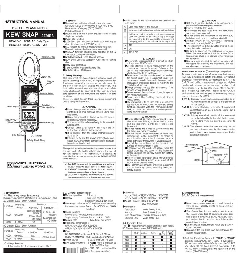
Other manuals for KEW 1018
1
Table of contents
Other KYORITSU Multimeter manuals

KYORITSU
KYORITSU New SNAP 7 User manual

KYORITSU
KYORITSU KEW 4106 User manual

KYORITSU
KYORITSU KEW MATE 2012RA User manual

KYORITSU
KYORITSU KEW1020R User manual

KYORITSU
KYORITSU KEW1011 User manual

KYORITSU
KYORITSU KEW 1018 User manual

KYORITSU
KYORITSU KEW 1061 User manual

KYORITSU
KYORITSU KEW 1109 User manual

KYORITSU
KYORITSU KEW MATE 2000A User manual

KYORITSU
KYORITSU KEW 1052 User manual