Kaiweets ST600X User manual

KAIWEETS
User
Manual
Smart
Digital
Multimeter
ST600X
&
ST600Y
Made
in
China
CERoHS
&
& A
®ES
Contact
us:
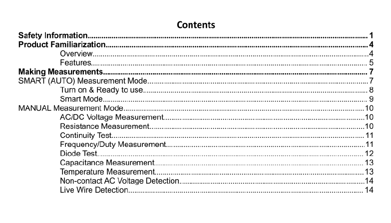
Contents
Safety
Information.
Product
Familiarization..
Overview.
Features.
Making
Measurement:
SMART
(AUTO)
Measurement
Mode..
Tum
on
&
Ready
to
use...
Smart
Mode......
-
MANUAL
Measurement
Mode.
AC/DC
Voltage
Measurement.
Resistance
Measurement.
Continuity
Test.........
Frequency/Duty
Measurement.
Diode
Test....
S—
Capacitance
Measurement.
Temperature
Measurement.
Non-contact
AC
Voltage
Detectiol
Live
Wire
Detection....
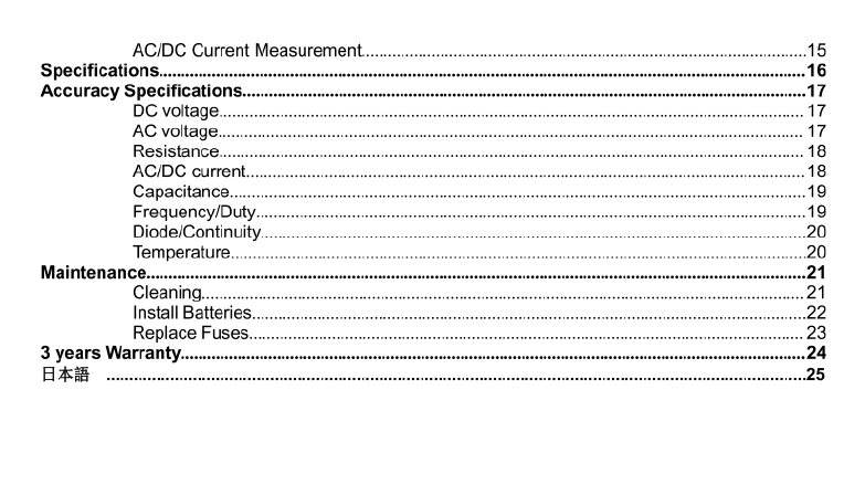
AC/DC
Current
Measurement.
15
Specifications.
Accuracy
Specification:
DC
voltage....
AC
voltage..
Resistance.
AC/DC
current..
Capacitanc
Frequency/Dut
Diode/Continuity.....
Temperature..
Maintenance.
Cleaning.....
Install
Batteries.
Replace
Fuses.
3
years
Warranty.
EES]
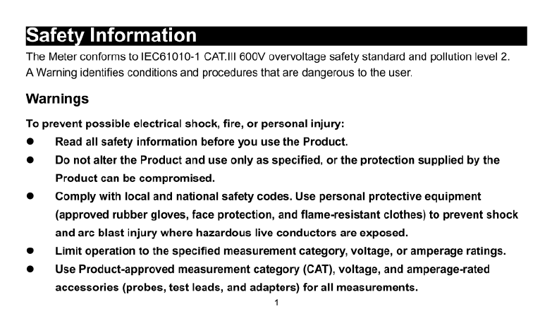
Safety
Information
The
Meter
conforms
to
IEC61010-1
CAT.IIl
600V
overvoltage
safety
standard
and
pollution
level
2
AWarning
identifies
conditions
and
procedures
that
are
dangerous
to
the
user.
Warnings
To
prevent
possible
electrical
shock,
fire,
or
personal
injury:
Read
all
safety
information
before you
use
the
Product.
Do
not
alter
the
Product
and
use
only
as
specified,
or
the
protection
supplied
by
the
Product
can
be
compromised.
Comply
with
local
and
national
safety
codes.
Use
personal
protective
equipment
(approved
rubber
gloves,
face
protection, and
flame-resistant
clothes)
to
prevent
shock
and
arc
blast
injury
where
hazardous
live
conductors
are
exposed.
Limit
operation
to
the
specified
measurement
category,
voltage,
or
amperage
ratings.
Use
Product-approved
measurement
category
(CAT),
voltage,
and
amperage-rated
accessories
(probes,
test
leads,
and
adapters)
for
all
measurements.
1

Do
not
touch
voltages
>30
V
AC
RMS,
42
V
AC
peak,
or
60
V
DC.
Use
the
correct
terminals,
function, and
range
for
measurements.
Do
not
use
the
Product
around
explosive
gas,
vapor,
or
in
damp
or
wet
environments.
Do
not
operate
the
Product
with
covers
removed
or
the
case
open.
Hazardous
voltage
exposure
is
possible.
Examine
the
case
before you use
the
Product.
Look
for
cracks
or
missing
plastic.
Carefully
look
at
the
insulation
around
the
terminals.
Disconnect
power
and
discharge
all
high-voltage
capacitors
before you
measure
resistance,
continuity,
capacitance,
or
a
diode
junction.
Do
not
apply
more
than
the
rated
voltage,
between
the
terminals
or
between
each
terminal
and
earth
ground.
Remove
circuit
power
before you
connect
the
Product
in
the circuit
when
you
measure
current.
Connect
the
Product
in
series
with
the
circuit.
Measure
a
known
voltage
first
to
make
sure
that the
Product
operates
correctly.
2

Do
not
use
test
leads
if
they
are
damaged.
Examine
the test
leads
for
damaged
insulation,
exposed
metal,
or
if
the
wear
indicator
shows.
Check
test
lead
continuity.
Remove
the
input
signals before you
clean
the
Product.
When
measuring,
please
connect
the
null
or
ground
wire
first,
then
the
live
wire;
when
disconnected,
please
disconnect
the
live
wire
first,
and
then
the
null
or
ground
wire.
Remove
the
probe
from
the
Meter
before
opening
the
case
or
battery
cover.
Do
not
use
the
Meter
when
the
Meter
is
disassembled
or
the
battery
cover
is
opened.
The
Meter
can
only
be
used
together
with
the
probe
provided
to
meet
the
requirements
of
the
safety
standard.
If
the
probe
is
damaged
and
needs
to
be
replaced,
the
probe
of
the
same
model
and
electrical
specification.

Product
Familiarization
Overview
o)
i
@Alarm
Indicator
7
@LCD
Screen
@®Function
Buttons
@Current
Input
Jack
(©COM
Jack
®Jack
for
other
functions
S
U
U
U
U
77
@NCV
Sensor
g
§
‘
®Fiashiight
O/
—\Y

Features
Button
Function
Press
and
hold
the
*
(1)
button
for
about
2
seconds
to
turn
on/off
the
Meter.
Power
on
is
in
SMART
mode
by
default.
Press
the
'
[&
'
button
to
select
functions
from
right
to
left.
Press
the
*[&'
button
to
select
functions
from
eft
o
right.
Press
]
or
[
button
for
about
2
seconds
to
return
to
SMART
mode.
ST600X ST600Y
Press
'
%‘I
'El
"button
to
turn
on/off
data
holding.
Press
'
fi'
button
for
about
2
seconds
to
turn
on/off
backlight.
*Only
ST600X.
Press
'
button
to
select
functions.
*Only
valid
for
voltage
test,
current
test
and
NCV/live
test.
Press
'[£]"
button
for
about
2
seconds
to
turn
on/off
flashlight.

Symbol
Description
=
Damaged
Fuse
fthe
fuse
is
bumt
out,
the
symbol
'
£=F
*
will
be
displayed.
In
current
test,
the
symbol
*
FUSE
will
also
be
displayed.
The
current
can
only
be
measured
after
replacing
the
good
fuse.
0}
Auto
Power
Off
The
Auto
Power
Off
function
by
default
at
boot
and
*
(%
'
symbol
will
be
displayed.
Without
any
operation
in
about
15
minutes,
the
Meter
will
automatically
turmn
off.
1
minute
before
turn
off,
there
will
be
5
beeps.
Press
and
hold both
*
L%
*and*
power
off
function
will
be
canceled.
The
'€%"
symbol
is
not
displayed.
'
buttons
to
turn
on
meter,
the
auto
(223
Jack
Indication
When
switching
to
other
functions
the
light
above
the
corresponding
jack
will
flash
for
users
to
insert
the
right
test
leads
to
the
right
jack

Making
Measurements
When
connecting
the
test
leads
to
the
circuit
or
device,
connect
the
common
(COM)
test
lead
before
connecting
the
live
lead;
when
removing
the
test
leads,
remove
the
live
lead
before
removing
the
common
test
lead.
Warnings
©Do
not
measure
the
voltage
higher
than
600V,
otherwise,
the
Meter
may
be
damaged.
Pay
attention
when
measuring
high
voltage
to
avoid
electric
shock
or
personal
injury.
@Before
use,
test
the
known
voltage
or
current
to
confirm
that the
Meter
is in
good
condition.
SMART
(AUTO)
Measurement
Mode
The
Meter
defaults
to
SMART
mode.
In
the
SMART
mode,
the
Meter
can
test
DC
voltage,
AC
voltage,
resistance,
continuity,
it
selects
the
range
with
the
best
resolution
automatically.
Table of contents
Other Kaiweets Multimeter manuals

Kaiweets
Kaiweets KM601 User manual

Kaiweets
Kaiweets KM100 User manual

Kaiweets
Kaiweets HT118A User manual

Kaiweets
Kaiweets KM601s User manual

Kaiweets
Kaiweets ST500Y User manual

Kaiweets
Kaiweets KM100 User manual

Kaiweets
Kaiweets KM312AB User manual

Kaiweets
Kaiweets KM602 User manual

Kaiweets
Kaiweets KM201 User manual

Kaiweets
Kaiweets HT118A User manual

Popular Multimeter manuals by other brands


Gossen MetraWatt
Gossen MetraWatt METRAmax 6 operating instructions

PeakTech
PeakTech 4000 Procedure of calibration

YOKOGAWA
YOKOGAWA 90050B user manual

Gossen MetraWatt
Gossen MetraWatt METRALINE DMM16 operating instructions

Fluke
Fluke 8846A Programmer's manual

Tempo Communications
Tempo Communications MM200 instruction manual


