Kalor Paola 13-13D User manual

USER MANUAL
Paola 13-13D / Chiara 15-15D - Insert Stoves
Instructions for the correct use and maintenance of
your Kalor wood pellet stove
Distribution and warranty in Ireland by:

A note from the distributor:
Congratulations and thank you for choosing a Kalor wood pellet stove. Kalor is a leading
wood pellet stove brand worldwide, offering leading combustion efficiencies and superior
reliability. You have chosen well!
Kalor stoves are distributed in Ireland by Wood Pellet Stoves.ie, through a network of
Authorised Dealers. We are a company, totally dedicated to wood pellet stoves and boilers
and our priorities are quality, not just of product but also of the installation and
maintenance.
We also support a nationwide network of Authorised Technicians who are specially trained
on Kalor wood pellet stoves and boilers. This ensures that your stove can be correctly
installed, commissioned, maintained and repaired by competent personnel and that you
receive the best possible service, all the way from purchasing your stove to the end of its
life-cycle.
Please refer to the notes on the inner back cover of this manual for further details
regarding the installation, commissioning and warranty for your stove/boiler.
We wish you all the best with your new Kalor stove/boiler and hope it serves you well for
many, many years.
Yours sincerely,
_____________________________
Fergus Mc Manamon
General Manager
Wood Pellet Stoves.ie

73
EN
Dear Customer,
We thank you for having chosen one of our products, the fruit of technological experience and of
continual research for a superior quality product in terms of safety, dependability, and service.
In this manual you will nd all the information and useful suggestions to use your product with the
maximum safety and efciency.
• Incorrect installation, incorrectly performed maintenance, improper use of the product release the
manufacturer from every eventual damage derived from the use of the Insert.
• The unit cannot be used as an incinerator. Do not use fuels other than pellets.
• This manual has been realized by the manufacturer and constitutes an integral part of the product
and must remain with it during its entire lifetime. If the product is sold or transferred, be sure that
the booklet is present since the information contained in it are addressed to the buyer, and to all
those persons of various titles who complete the installation, use and maintenance.
• Carefully read the instructions and the technical information contained in this manual, before pro-
ceeding with the installation, use, and any operation on the product.
• The observance of the indications contained in the present manual guarantees the safety of peo-
ple and the product, the economy of use and a longer functioning lifetime.
• Although the carefully studied design and the risk analysis done by our company has permitted
the realization of a safe product, in any case, before effecting any operation on the Insert, it is rec-
ommended to keep said manual available and pay scrupulous attention to the instructions written
therein.
• Be very careful when moving the ceramic details where present.
• Check the precise atness of the pavement where the product will be installed
• The wall where the product will be placed must not be constructed in wood, or in any case, made
of an inammable material, and in addition it is necessary to maintain a safety distance.
• While the Insert is in operation, several parts of the Insert (door, handle, sides) can reach high
temperatures. Therefore pay attention and use the proper precautions, above all in the presence
of children, elderly or disabled persons, and animals.
• Assembly must be performed by authorized persons (Authorized Assistance Center).
• Diagrams and drawings are furnished for the purpose of illustration; the manufacturer, with the
intent of pursuing a policy of constant development and renewal of the product can, without any
notice, make any modications that are believed opportune.
• When the Insert is working at its maximum speed, it is strongly suggested to wear gloves while
handling with the door for pellets loading and the door handle.
• It is prohibited to install in bedrooms or in explosive environments.
• Only use replacement parts recommended by the supplier.
In the event of a re, disconnect the power supply, use an extinguisher and call the re ght-
ers if necessary. After that contact the Authorized Assistance Center.
Never cover the body of the Insert in any way or obstruct the openings placed on
the upper side when the device is operating. All our Inserts are trial lighted on the
construction line.
We highly recommend to turn to our Authorized Service Centre for the installation
and the rst ignition of the device as it not only carries out the installation
perfectly but also veries the regular operation of it.
Inserto Camino 13_15 / 13C_15C
Co d. 0 01112

74
EN
INFORMATION:
This symbol is used to highlight information which is important for proper Insert
operation. Failure to comply with these provision will compromise use of the Insert and
its operation will not be satisfactory.
ATTENTION:
This warning sign indicates that the message to which it refers should be carefully read
and understood, because failure to comply with what these notices say can cause
serious damage to the Insert and put the user’s safety at risk.
This instruction booklet is an integral part of the product: make sure that it always accompanies the
appliance, even in case of transfer to another owner or in the case of transfer to another place. In
the event of damage or loss, request a copy from the area technician.
These symbols indicate specic messages in this booklet:
Norms and declarations of conformity
• Our company declares that the stove
conforms to the following norms for the EC
European Directive labelling:
• 2014/30 UE (regulation EMCD) and
following amendments;
• 2014/35 UE (Low Voltage Directive) and
following amendments;
• 2011/65 EU (RoHS 2 directive);
• The Rules of Construction Products (CPR-
Construction Products Regulation) No.
305/2011 regarding the construction world;
• For installations in Italy, please refer to
UNI 10683/98 or following changes. For
the water-thermo-sanitary equipment,
let the installer give you the conformity
declaration in compliance with L. 37/2008.
While installing the unit respect the
local, national and Europen rules;
• EN 55014-1; EN 55014-2; EN 61000-3-2;
EN 61000-3-3; EN 60335-1; EN 60335-2-
102; EN 62233, EN 50581.
Safety information
Please carefully read this use and maintenance
manual before installing and operating the
stove!
If clarication is needed, please contact the
dealer or the Authorized Assistance Center.
• The pellet stove must only be operated
in living environments. This stove, being
controlled by an electronic board, permits
a completely automatic and controlled
combustion; the exchange, in fact, regulates
the lighting phase, 5 power levels and the shut
down stage, guaranteeing the safe operation of
the stove.
• The basket used for combustion allows most
of the ash produced by the combustion of the
pellets to fall into the collection compartment.
Nevertheless, check the basket daily, given
that not all pellets have high quality standards
(use only quality pellets recommended by the
manufacturer).

75
EN
Responsibility
With the delivery of the present manual, we de-
cline all responsibility, both civil and penal, for
accidents deriving from the partial or total lack
of observance of the instructions contained
herein.
We decline every responsibility derived from
improper use of the stove, from incorrect use
by the user, from unauthorized modications
and/or repairs, from the use of replacement
parts that are not original for this model.
The manufacturer declines every civil or penal,
direct or indirect responsibility due to:
• Lack of maintenance;
• Failure to observe the instructions contained
in the manual;
• Use in non-conformity with the safety direc-
tives;
• Installation in non-conformity with the norms
in force in the country;
• Installation by unqualied or untrained per-
sonnel;
• Modications and repairs not authorized by
the manufacturer;
• Use of non-original replacement parts;
• Exceptional events.
• Use only wood pellets;
• Keep / store the pellets in a cool
dry place;
•Never pour pellets directly on the
hearth;
• The Insert must only be fed with quality
6 mm diameter pellets, A1 certied
according to the UNI EN ISO 17225-2
regulations;
• Before making the electrical connection
of the Insert the discharge tubes must
be connected with the ue;
• The protective grill placed inside the
pellet container must never be removed;
• The environment where the Insert is
installed must have a sufcient exchange
of air;
• It is forbidden to operate the Insert with
the door open or the glass broken;
• Do not use the Insert as an incinerator;
the Insert should be used only for the
intended purpose;
• Any other use is considered improper
and therefore dangerous. Do not put in
the hopper other than wood pellets;
• When the Insert is operating, the
surfaces, glass, handle and tubes
become very hot: during operation do
not touch these parts without adequate
protection;
• Keep the fuel and other inammable
materials off the Insert.

76
EN
Charge pellet
Fuel is loaded from the upper part of the Insert
by opening a door.
Pour the pellets in the hopper.
This is easier if performed in two steps:
• Pour half of the contents of the bag into the
hopper and wait for the fuel to settle on the
bottom.
• Then pour in the second half;
• Keep the cover closed , after loading the pellets
, the lid of the fuel tank;
The Insert is a product by heating, presents
the external surfaces particularly hot. For this
reason, we recommend extreme caution when
operating in particular:
• Do not touch the Insert body and the various
components, do not approach the door , it could
cause burns;
• Do not touch the exhaust fumes;
• Do not perform any type of cleaning;
• Do not dump the ashes;
• Do not open the ash tray;
• Be careful that children do not come near;
Never remove the protection grille
in the hopper. When lling, do not
let the sack of pellets touch any
hot surfaces.
It is mandatory to extract the
Insert
only when it is completely off and free of
embers, because by extracting it, it disconnects from the
ue pipe
.
By installing the side load (optional) you can load the pellet without turning off
the
Insert.

77
EN
• The device can be used by children that are not
less than 8 years old and people with reduced
physical, sensory or mental capabilities, or lack
of experience or knowledge, provided being
under supervision of someone responsible or
after having received instructions relating to the
safe use of the device and to the understanding
of the dangers inherent to it. Children should not
play with the device. Cleaning and maintenance
to be performed by the user should not be made
by children without supervision;
• Do not use the Insert as a ladder or scaffold;
• Do not put clothes to dry on the Insert.
Any clothes hangers and suchlike must be kept
a suitable distance from the Insert. - Risk of re
• Carefully explain that the Insert is made from
material subjected to high temperatures for
the elderly , the disabled, and in particular for
all children, keeping them away from the Insert
during operation
• Do not touch the Insert with wet hands: the
Insert has electrical components that could
produce sparks if handled incorrectly.
• Never open the glass door of the pellet Insert
while the Insert is in operation.• The Insert must
be connected to an electrical system equipped
with an earthing conductor in accordance with
regulations 73/23 and 93/98 EEC;
• The system must be of adequate electrical
power declared the Insert;
• Do not wash the inside of the Insert with water.
The water could damage the electrical insulation,
causing electric shock;
• Do not expose your body to hot air for a long
time. Do not overheat the room you are in and
where the Insert is installed.
This can damage the physical conditions and
cause health problems;
• Do not expose to direct the ow of hot air
plants or animals;
• The pellet Insert is not a cooking element;
• External surfaces during operation can become
very hot. Do not touch them except with the
appropriate protection.
• The plug of the device power cable must be
connected only after installation and assembly
of the device and must remain accessible after
installation, if the unit is not provided of a double-
pole switch suitable and accessible.
• Do not lay objects, glasses, infusers, room
perfumers on the Insert, they could be damaged
or to damage the Insert (in this case de warranty
does not respond).
Instructions for safe and efcient use

78
EN
Technical Specication Insert 13_15 / 13C_15C
N.B.
1 - Measures with a tolerance of about 10 mm
2 - Measures and images are indicative and can
vary depending on the aesthetic of the
pellet Insert.
TOLLERANZE GENERALI DI LAVORAZIONE
DIMENSIONI LINEARI
± 0,15± 0,05
3,2 ± 0,1
DIMENSIONI ANGOLARI
PRECISIONE
12
GRADO DI
FINO A
± 0,15
± 0,1
6
± 0,3
± 0,25
120
± 0,2
± 0,15
60
660
± 0,3± 0,2 ± 0,5
4000
± 0,8
± 0,6
1000
400
± 0,5
± 0,4
400
120
± 2
± 1,5
4000
2000
± 1
± 1,2
2000
1000 DA
A
± 2.5
± 3,5
OLTRE
CAMPO TOLLERANZA
LUNGH. LATO CORTO
± 3°
FINO A 10
± 2°
DA 10 A 50
± 1°
DA 50 A 150
± 30'
OLTRE 150
AAAAA
DADADADADA
36030 San Vito di Leguzzano(VI) - ITALIA
Il presente disegno rimane di proprietà di AMG S.p.A.
Ci riserviamo di tutelare i nostri diritti a termini di legge
Spessore
Peso
Materiale
Colore
Scala Data
Disegnato Approvato
Rev. Data Dis.
A
DESCRIZIONE
Modifica
B
C
D
E
F
G
MZ
INSERTO 13C-15C
28/06/2018
Via delle Arti e dei Mestieri 1/3
H
I
Trattamento
. v eRe c i d oC
1:10
200
Ø
200(loading entrance)
Ø
80 (Flue pipe)
66
840
647
800 (internal dimensions)
610 (internal dimensions)
700 (internal dimensions)
150
590
40 662
840
42
610
689
Ø 100 (Channeling)
where present
TOLLERANZE GENERALI DI LAVORAZIONE
DIMENSIONI LINEARI
± 0,15± 0,05
3,2 ± 0,1
DIMENSIONI ANGOLARI
PRECISIONE
12
GRADO DI
FINO A
± 0,15
± 0,1
6
± 0,3
± 0,25
120
± 0,2
± 0,15
60
660
± 0,3± 0,2 ± 0,5
4000
± 0,8
± 0,6
1000
400
± 0,5
± 0,4
400
120
± 2
± 1,5
4000
2000
± 1
± 1,2
2000
1000 DA
A
± 2.5
± 3,5
OLTRE
CAMPO TOLLERANZA
LUNGH. LATO CORTO
± 3°
FINO A 10
± 2°
DA 10 A 50
± 1°
DA 50 A 150
± 30'
OLTRE 150
AAAAA
DADADADADA
36030 San Vito di Leguzzano(VI) - ITALIA
Il presente disegno rimane di proprietà di AMG S.p.A.
Ci riserviamo di tutelare i nostri diritti a termini di legge
Spessore
Peso
Materiale
Colore
Scala Data
Disegnato Approvato
Rev. Data Dis.
A
DESCRIZIONE
Modifica
B
C
D
E
F
G
MZ
INSERTO 13C-15C
28/06/2018
Via delle Arti e dei Mestieri 1/3
H
I
Trattamento
. v eRe c i d oC
1:10
200
Ø
200(loading entrance
)
Ø
80 (Flue pipe)
66
840
647
800 (internal dimensions)
610 (internal dimensions)
700 (internal dimensions)
150
590
40 662
840
42
610
689
Ø 100 (Channeling)
where present
TOLLERANZE GENERALI DI LAVORAZIONE
DIMENSIONI LINEARI
± 0,15± 0,05
3,2 ± 0,1
DIMENSIONI ANGOLARI
PRECISIONE
12
GRADO DI
FINO A
± 0,15
± 0,1
6
± 0,3
± 0,25
120
± 0,2
± 0,15
60
660
± 0,3± 0,2 ± 0,5
4000
± 0,8
± 0,6
1000
400
± 0,5
± 0,4
400
120
± 2
± 1,5
4000
2000
± 1
± 1,2
2000
1000 DA
A
± 2.5
± 3,5
OLTRE
CAMPO TOLLERANZA
LUNGH. LATO CORTO
± 3°
FINO A 10
± 2°
DA 10 A 50
± 1°
DA 50 A 150
± 30'
OLTRE 150
AAAAA
DADADADADA
36030 San Vito di Leguzzano(VI) - ITALIA
Il presente disegno rimane di proprietà di AMG S.p.A.
Ci riserviamo di tutelare i nostri diritti a termini di legge
Spessore
Peso
Materiale
Colore
Scala Data
Disegnato Approvato
Rev. Data Dis.
A
DESCRIZIONE
Modifica
B
C
D
E
F
G
MZ
INSERTO 13C-15C
28/06/2018
Via delle Arti e dei Mestieri 1/3
H
I
Trattamento
. v eRe c i d oC
1:10
200
Ø
200(loading entrance)
Ø
80 (Flue pipe)
66
840
647
800 (internal dimensions)
610 (internal dimensions)
700 (internal dimensions)
150
590
40 662
840
42
610
689
Ø 100 (Channeling)
where present
TOLLERANZE GENERALI DI LAVORAZIONE
DIMENSIONI LINEARI
± 0,15± 0,05
3,2 ± 0,1
DIMENSIONI ANGOLARI
PRECISIONE
12
GRADO DI
FINO A
± 0,15
± 0,1
6
± 0,3
± 0,25
120
± 0,2
± 0,15
60
660
± 0,3± 0,2 ± 0,5
4000
± 0,8
± 0,6
1000
400
± 0,5
± 0,4
400
120
± 2
± 1,5
4000
2000
± 1
± 1,2
2000
1000 DA
A
± 2.5
± 3,5
OLTRE
CAMPO TOLLERANZA
LUNGH. LATO CORTO
± 3°
FINO A 10
± 2°
DA 10 A 50
± 1°
DA 50 A 150
± 30'
OLTRE 150
AAAAA
DADADADADA
36030 San Vito di Leguzzano(VI) - ITALIA
Il presente disegno rimane di proprietà di AMG S.p.A.
Ci riserviamo di tutelare i nostri diritti a termini di legge
Spessore
Peso
Materiale
Colore
Scala Data
Disegnato Approvato
Rev. Data Dis.
A
DESCRIZIONE
Modifica
B
C
D
E
F
G
MZ
INSERTO 13C-15C
28/06/2018
Via delle Arti e dei Mestieri 1/3
H
I
Trattamento
. v eRe c i d oC
1:10
200
Ø
200(loading entrance)
Ø
80 (Flue pipe)
66
840
647
800 (internal dimensions)
610 (internal dimensions)
700 (internal dimensions)
150
590
40 662
840
42
610
689
Ø 100 (Channeling)
where present

79
EN
PARAMETRO UNITÀ DI MISURA ICP13_13C ICP15_15C
Heat input kW 13,3 15,1
Nominal heat output kW 12 13,5
Reduced heat output kW 5,1 5,1
CO concentration at nominal
reference (13% O
2
)
mg/m384 83
CO concentration at reduced
reference (13% O
2
)
mg/m3134 134
Nominal efciency % 90,6 89,5
Reduced efciency % 94,3 94,3
Pellet consumption (min-max) Kg/h 1,1 - 2,7 1,1 - 3
Heated surface mc 320 350
Flue gas ow rate (min-max) g/s 4,55 - 9,26 4,55 - 9,78
Draft advised (min-max) Pa 3 - 10 3 - 10
Flue gas temperature (min-max) °C 85 - 148 85 - 173
Tank capacity Kg 22 22
Diameter smoke outlet tube mm 80 80
Diameter air intake mm 50 50
Nominal voltage V 230 230
Nominal frequency Hz 50 50
Power consumption max W 320 320
Nominal Power consumption W 115 120
Insert weight Kg 108 108
Insert weight with base Kg 145 145
EEI 128 126
N° Test Report K 2343 2018 T1
Energetic class A +
Enviromental decree n.186
Dust at 13% O2 at nominal heat output mg/m320 23
It is recommended the control of emissions after installation.
In order to achieve the test report results, please load the performance parameters retained
by the manufacturer and the qualied technician. They will use these parameters once veried
that, during the installation, it is possibile to reproduce the laboratory conditions.

80
EN
Operating area
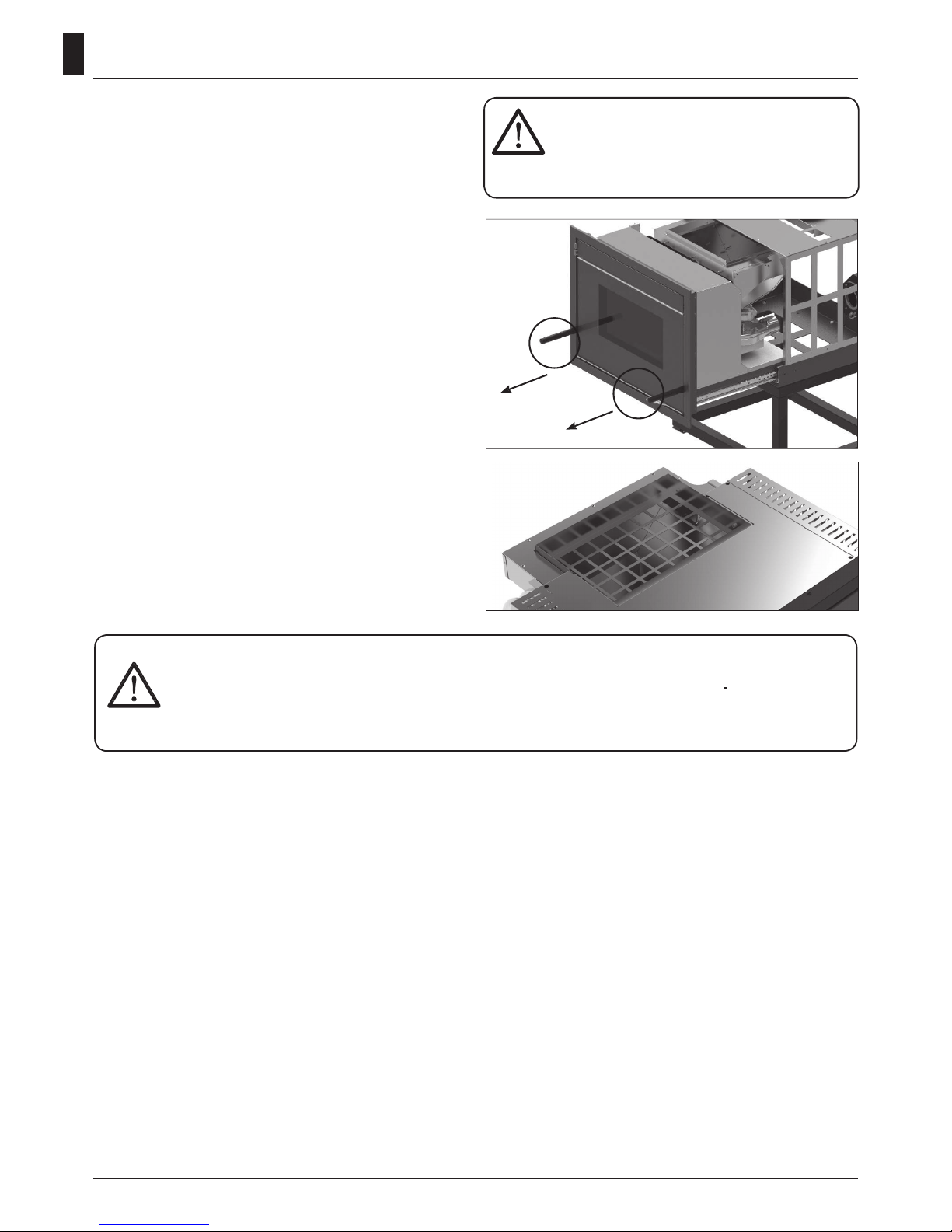
How to place the Insert
For proper functioning and a good temperature
distribution, the Insert shoul be positioned
in a location where it is able to take in the air
necessary for combustion of the pellet (about
40 m3/h must be available), as laid down in
the standard governing the installation and in
accordance with local national standards.
The volume of the room must not be less than
30 m3.
The air must come in through permanent
openings made in walls (in proximity to the Insert)
which give onto the outside, with a minimum
cross-section area of 100 cm2.
These openings must be made in such a way
that it is not possible for then to be obstructed
in any way. Alternatively, the air can be taken
from rooms adjacent to the one which needs
ventilating, as long as they are provided with
an air intake from the outside, and are not used
as bedrooms or bathrooms, and provided there
is no re risk such as there is for example in
garages, woodsheds, and storerooms, with
particular reference to what is laid down in
current standards.
It is not permissible to install the
Insert in bedrooms, bathrooms, or
in a room where another heating
appliance is installed (Insert,
Insert etc.) which does not have its own
independent air intake. Locating the Insert
in a room with an explosive atmosphere
is prohibited. The oor of the room where
the Insert is to be installed must be strong
enough to take its weight. Keep a minimum
distance of 5 cm between the covering and
the replace insert. If walls are ammable,
maintain a minimum distance of 20 cm at
the rear , of 40 cm at the side and 100 cm
at the front. If the room contains objects
which are believed to be particularly
delicate, such as drapes, sofas and other
furniture, their distance from the Insert
should be considerably increased. The two
side walls of the chimney insert must be
accessible for maintenance by authorized
technicians.
Connection to the external air intake
It is essential that at least as much air must be
able to ow into the room where the Insert is
installed as is required for proper combustion in
the appliance and for the ventilation of the room.
This can be effected by means of permanent
openings in the walls of the room to be ventilated,
which give onto the outside, or by single or
collective ventilation ducts.
For this purpose, on the external wall near the
Insert, a hole must be made with a minimum free
cross-section of 100 cm2. (equivalent to a round
hole of 12 cm diameter or a square hole 10x10
cm) protected by a grille on the inside and the
outside.
The air intake must also: communicate directly
with the room where the Insert is installed be
protected by a grille, metal mesh or suitable
guard, as long as this does not reduce the area
below the minimum.
Be positioned in such a way as to be impossible
to obstruct.
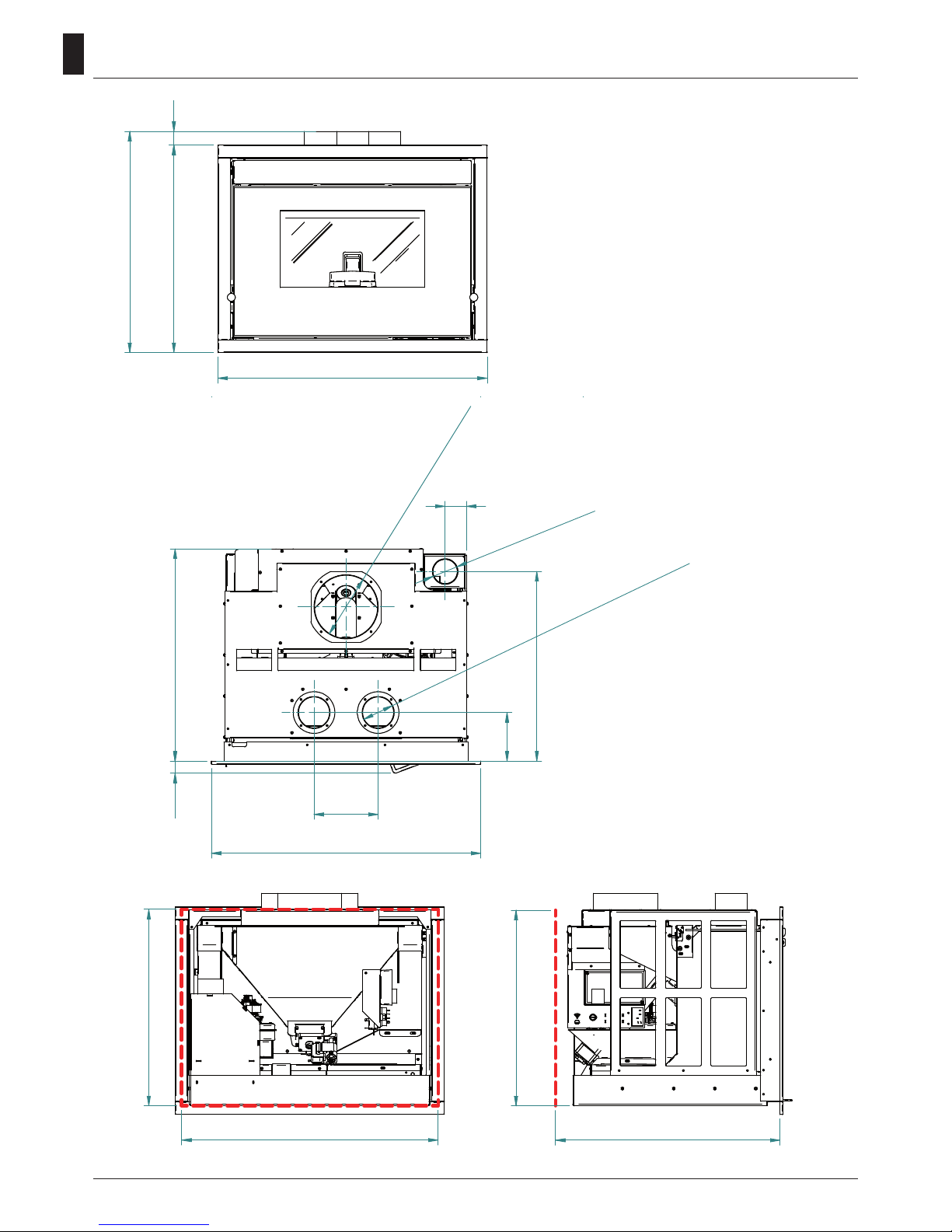
Distances to consider for the installation of stoves,
thermo-stoves, hydro and air inserts.
40 cm
20 cm
Min.
100 cm2
100 cm
20 cm
(A)
(B)

81
EN
Connection to the ue pipe
The ue pipe must have internal dimensions not
larger than 20x20 cm, or diameter 20 cm. In the
event of larger dimensions, or of the ue pipe
being in poor condition ( for example cracks, poor
insulation, etc.), it is advisable to t a stainless
steel pipe of suitable diameter inside the ue pipe
throughout its length, right up to the top. Check
with suitable instruments that there is a draught
between 3 Pa and 10 Pa. This type of connection
ensures the evacuation of the fumes even in the
event of a temporary power cut. At the bottom of
the ue pipe, provide an inspection cap to allow
periodic checking and cleaning, which must be
done annually. Make a gas-tight connection to
the ue pipe, using pipes and connectors as
recommended by us. You must ensure that a
windproof cowl should be tted which complies
with the standards in force.
Connection to an external ue with insulated
or double-wall pipe
The only type of pipe which is permissible is
insulated (double-walled) stainless steel, smooth
on the inside, xed to the wall. Flexible stainless
steel pipe must not be used. At the bottom of
the ue pipe, provide an inspection cap to allow
periodic checking and cleaning, which must be
done annually. Make a gas-tight connection to
the ue pipe, using pipes and connectors as
recommended by us. You must ensure that a
windproof cowl should be tted which complies
with the standards in force. Check with suitable
instruments that there is a draught between 3 Pa
and 10 Pa.
Connection to the ue pipe
For proper functioning, the connecting pipe
between the Insert and the chimney or ue duct
must have a slope of not less than 3% in the
horizontal stretches, the length of which must
not exceed 2 metres and the vertical distance
between one tee connector and another (change
of direction) must not be less than 1,5 m.
Check with suitable instruments that there is a
draught between 3 Pa and 10 Pa. At the botton of
the ue pipe, provide an inspection cap to allow
periodic checking and cleaning, which must
be done annually. Make a gas-tight connection
Fig. 3: connection to an
external ue with insulated or
double-wall pipe.
Fig. 2: connection to the
ue pipe.

82
EN
to the ue pipe, using pipes and connectors as
recommended by us. You must ensure that a
windproof cowl should be tted which complies
with the standards in force.
Fireplace ue gas
Avoid contact with combustible materials
(example: wooden beams) and in any case
provide for their insulation with ame retardant
material. In case of pipe penetrations through
roofs or walls is recommended to use special kits
crossing, certicates, are available commercially.
In the event of a chimney re, turn off the Insert,
disconnect from the network and never open the
door. Then call the authorities.
The chimney cap
The chimney cap must respect the following
requirements:
• It must have the equivalent diameter and
internal form of the ue.
• It must have a useful outlet diameter of not less
than double that of the ue.
• The chimney cap on the roof or that remains in
contact with the outside (for example, in case
of open lofts or attics), must be covered with
elements in brick or tile and must, in any case,
be well insulated.
• It must be constructed to prevent rain, snow,
and extraneous bodies from entering the ue
and so that the discharge of the products of
combustion is not inhibited by wind from any
quarter or strength (wind-proof chimney cap).
• The chimney cap must be positioned in such
a way as to guarantee the adequate dispersion
and dilution of the products of combustion and
in any case, must be out of the reux zone.
This zone has different dimensions and forms
according to the angle of inclination of the roof
so it is necessary to adopt minimum heights
• The chimney cap must be a wind-proof type
and must be above the ridge.
• Eventual structures or other obstacles that are
higher than the chimney cap must not be too
close to the chimney cap itself.
Characteristics of chimney
YES NO
REMARKS:
- the appliance must be installed by a qualied
technician in possession of the technical and
professional requirements according to the
DM37/2008 that, under its responsibility, to
ensure compliance with the rules of good
technique.
- the Insert must be connected to a heating
system and/or to a network of production
of sanitary hot water, consistent with its
performance and its power
- you need to keep in mind all laws and national,
regional, provincial and municipal laws of the
country in which you installed the device
- check that the oor is not ammable: if
necessary use a suitable platform
- in the room where the generator must be
installed to heat must not pre-exist or be installed
with an extractor hood or ventilation ducts of the
collective type.
Should these devices be located in adjacent
rooms communicating with the installation, and
‘prohibited the simultaneous use of the heat
generator, where there is a risk that one of the
two rooms being placed in depression than the
other
- it is not permissible to install in bedrooms or
bathrooms

83
EN
The assembly of the side loading system
must be done before the construction of the
replace insert coating.
Connect the exible hose to the loading tank
present on the tank calculating the useful
length of the pipe with a minimum inclination
of 50°.
Now t the side loading tank in the coating and connect the hose.
Side loading system (Optional)
If you have bought the replace insert pedestal,
rst you have to x it to the oor and choose the
height of the legs. If you install the lateral load, it
is advisable to keep the minimum size so as not
to have the loading entrance too high.
Pedestal xing (Optional)
Insert assembly
Insert xing
If you have purchased the replace insert
pedestal, rst you have to x it to the oor and
choose the height of the legs. Fix the replace
insert to the base or to the pedestal using the
xing screws (not supplied).
If the replace is already existing, the side
openings for access must be provided.
Fixing screws
Fixing screws

84
EN
It is mandatory to have an opening in the
brick / plasterboard coating to guarantee an
adequate supply of air to the chimney.
It is recommended to replicate the same
opening made on the perimeter wall.
Alternatively, the suction pipe (Ø 50 mm) can
be connected to the outside of the home. If
the suction tube is taken only outside of the
brick cladding, it is mandatory to have an air
intake on the perimeter wall of the house.
Remember that it is forbidden to
inhale the combustion air from
bedrooms, bathrooms, garages or
deposits that could have explosive
atmospheres.
The pellets are cylinders of compressed wood, produced from sawdust and wood
processing (chips and sawdust), generally produced by sawmills and carpenters.
The binding capacity of the lignin contained in wood, allows to obtain a
compact product without adding additives and foreign chemicals to
the wood, is therefore obtained a natural fuel with high yield.
The use of expired pellets or any other unsuitable material can
damage parts of the Insert and impair proper operation: this
can lead to the termination of the guarantee, and its producer
responsibility.
For our products use pellets diameter 6 mm, length 30 mm and a maximum of 6% and A1
certied according to the UNI EN ISO 17225-2 standard. Keep the pellets away from heat
sources and not in humid environments or with explosive atmosphere.
Pellet
Remote Control
The remote control (Fig. 3) used to adjust water
temperature power and the on/off functions for
the pellet Insert.
To start the Insert, press key and the Insert will
automatically enter the starting phase.
Press keys + (1) and - (2) to adjust temperature,
and use keys + (6) and - (5) to adjust operating
power.
To turn off the Insert, hold down key .
To replace the 3 volt battery located on the back
of the remote control, pull the centre of the cover
and the lever on the side of the same, replace
the battery observing the correct polarity (Fig. 4) Fig. 3 Fig. 4
Fig. 3

85
EN
Contraow channel
It is possible to connect two pipes with Ø
100mm and a maximum length of 3 linear
meters each to allow the air to flow in other
enviroments. For each 45° curve you have to
calculate a 70cm loss of the linear section.
(example. maximum distance 3 meters,
maximum distance with a curve 3-0.7 = 2.3
meters).
It is possible to divide the air through the
front door. When the door is open the air
will come out from the front, and when the
door is closed the air will be pushed into the
channels.
Front door detail:
In detail, the bar to move to divide the air:
when the door is open (see photo) the air will
come out from the front, when the door is
closed the air will be ducted.
Front door open

86
EN
Mandatory microswitch connection
Only for not ducted Inserts
If the Insert is not ducted it is mandatory to
connect the microswitch located behind the
air's front door.
This operation must be done exclusively by
a specialized technician.
The microswitch is equipped with a shoulder
strap that must be connected in series to the
other safety devices as shown below:
1. Disconnect the cables coming from the
microswitch basement
(Foto 1 / 2)
2.
Now connect the microswitch cables of
the air's door to the cables that have just
been disconnected (Foto 3 / 4)
The male of the air door microswitch strap (A)
must be connected to the female that goes to
the electronic board (B). Connect the female of
the strap of the air door microswitch (C) with
the male of the riser coming from the base
microswitch (D).
This connection interrupts the pellet supply when the micro switch door is closed.
This is of fundamental importance because if the door is closed the hot air can not be released
into the room and the replace insert will overheat.
To avoid this, the specialized technician must check that the pellet feed functions should work
only with the Insert fully inserted and with the air ap open.
If the insert is ducted this connection is not necessary.
Foto 1 Foto 2
Foto 3 Foto 4
B
A
A
B
C
D
C
D

87
EN
Insert ignition
Remove any components which might burn from the rebox and from the glass
(various instructions and adhesive labels)
Charge pellet
Fuel is loaded from the upper part of the Insert by opening a door. Pour the pellets in the hopper.
When empty, this is easier if performed in two steps:
• Pour half of the contents of the bag into the hopper and wait for the fuel to settle on the bottom.
• Then pour in the rest.
Never remove the protection grille in the hopper. When lling, do not let the sack
of pellets touch any hot surfaces.
The brazier should be cleaned before each starting.
Control Panel
Button is used to switch on and / or off the Insert and to exit programming.
Buttons and are used to adjust temperature, for displays and for the programming functions.
Buttons and are used to adjust heating power.
Button e is used to adjust temperature and programming functions.
The upper and lower displays are used to view different messages.
SYMBOL DESCRIPTION
The LED is on when the parameter UT01 on the menu is not on OFF and the weekly
or daily programming are set.
The LED starts up every time the Insert is loading pellets
SET The LED blinks to indicate that you are entering the menu user/technician or that you
are modifying the temperature set.
Fan
acc

88
EN
Preliminary checks
Before switching on the pellet Insert, make sure that the pellet hopper is full, the combustion
chamber is clean, the glass door is closed, the power supply plug is connected and the switch on
the back is set to “1.”
TURNED OFF
The Insert is off.
TURNED ON
The Insert is in the rst ignition phase.
The glow plug and fume extractor are active.
LOAD PELLET
In this phase of the ignition process the Insert starts loading the pellets into the
brazier. The glow plug, the fume extractor and the cochlea engine are active.
FIRE PRESENT
In this phase of the ignition process the Insert starts loading the pellets into the
brazier. The fume extractor and the cochlea engine are active.
BRAZIER CLEANING
The Insert is cleaning the basket.
The smoke extractor runs at maximum speed and the pellet load is at minimum.
WORK
The Insert is working, in this case at power 3.
The detected room temperature is 21 ° C. During normal work, the fumes fan,
the auger motor and the room fan are active.
21 :10
22°C P-1
TURNED OFF
14 :35
22°C P-1
FIRE
present
14 :35
21°C P-2
ACCENDE
14 :35
21°C P-2
LOAD
pellet
15 :18
22°C P-3
WORK
15 :18
22°C p-2
BRAZIER
CLEANING
Information on the display

89
EN
Alarm signals
In the event of a working defect, the system informs the user about the type of failure occurred.
The following table summarises the alarms, kind of problem and possible solution:
Display Kind of problem Solution
ALAR 1 BLACK OUT There is no power supply
As soon as the power supply is back, the Insert
starts a cooling cycle: it will be necessary to
restart it manually
ALAR 2 PROBE
EXHAUST The smokes sensor is broken or
not connected to the pcb Contact an Authorized Assistance Center
ALAR 3 HOT
EXHAUST Smokes temperature too high
Switch off the Insert, allow it to cool down
and perform ordinary cleaning. If the problem
persists, contact an Authorized Assistance
Center for cleaning the Insert and the ue
ALAR 4 FAN
FAILURE Smokes extractor blocked or
broken Contact an Authorized Assistance Center
ALAR 5 NO
LIGHTIN The Insert cannot start up
This is the rst light-up
Fill in the tank with pellets
Start up again
ALAR 6 NO
PELLET The pellet Insert switched off
while working Fill in the tank with pellets
ALAR 7 SAFETY
THERMAL The water temperature exceeds
100°C.
Clean the inert and the ue. Reset the thermost
manually. If the problem persists, contact an
Authorized Assistance Center
ALAR 8 FAILURE
DEPRESS Obstructed ue Clean the ue or check there are no obstructed
grids near the smokes exhaust
SERV The Insert has worked for
1200 hours. Supplementary
maintenance required
Contact an Authorized Assistance Center
Regular checks should be carried out by the user, who should only contact the Authorized
Assistance Center if no solution is found.

90
EN
Programming menu
Menu 02 SET CLOCK
To access the set clock option, press the “SET” button (3), with the button - (5) scroll through the submenus
until MENU 02 - SET CLOCK and with buttons 1 and 2 select the current day. Press the “SET” button (3)
to conrm. Then use buttons 1 and 2 to set the time and press “SET” (3) to advance to the minutes setting
by pressing buttons 1 and 2. By pressing set again it’s possible to access various submenus in order to
set the date, day, month, and year. To do so, repeat the steps indicated above, using buttons 1, 2, and 3.
The following table briey describes the structure of the menu, focusing only on those selections which
are available to the user.
Set the current time and date. The device
comes equipped with a lithium battery
that allows the internal clock to operate
autonomously for over 3-5 years.
Menu 03 SET CHRONO
Press the “SET” button (3) and then button 5 to arrive at the desired menu; press “SET” (3) to enter.
Enter menu M-3-1 and with buttons 1 and 2 select whether or not to activate the thermostat (on/off),
which allows you to program the automatic ignition of the Insert.
Once the thermostat is activated/deactivated, press button “4” (OFF) and continue scrolling though the
submenus using button 5. Select which submenu you wish to enter in order to access the daily, weekly,
and weekend programmes.
To set the ignition times and days repeat the previous steps:
- access the submenu using “SET” (3)
- adjust the days, times, and activation status (on/off) with buttons 1 and 2
- conrm by pressing the “SET” button (3)
- exit from the submenu/menu with button 4 to turn it off
The following table briey describes the structure of the menu, focusing only on those selections which
are available to the user.
level 1 level 2 level 3 level 4 value
02 - set clock
01 - day day of the week
02 - hour hour
03 - minutes minutes
04 - day day of the month
05 - month month
06 - year year
menù level
input
dialogue
06
Menu 02
mese
orologio
1
2
3 6
5
4
level 1 level 2 level 3 level 4 value
03 - set thermostat
01 -
activate thermos.
01 -
activate thermos.
on/off
02 -
day programme
01 -
daily thermostat
on/off
02 - start 1 day hour
03 - stop 1 day hour
04 - start 2 day hour
05 - stop 2 day hour
This manual suits for next models
1
Table of contents
Other Kalor Stove manuals

Kalor
Kalor Angela 10 User manual

Kalor
Kalor Francesca 17B User manual

Kalor
Kalor Denia 14 Operation and installation manual

Kalor
Kalor Paola 13 User manual

Kalor
Kalor Ada 28B User manual

Kalor
Kalor Alessia User manual

Kalor
Kalor 24B User manual

Kalor
Kalor Cloe 17B User manual

Kalor
Kalor Petite 6 Operation and installation manual

Kalor
Kalor Lara 12D User manual
Popular Stove manuals by other brands

CASATELLI
CASATELLI CARLO PRO DESCRIPTION / CLEANING / TECHNICAL DATA

Chard
Chard SBBCS-85 Use and care instructions

Fröling
Fröling PECO installation instructions

Broseley
Broseley eVolution 4 Installation & operating instructions

Country Flame
Country Flame NPS-1000 owner's manual

Lifestyle
Lifestyle CA-GB17 instruction manual