NORDIC FIRE HRV VIKTOR Specification sheet

ENGLISH
Pellet boiler
stove
HRV VIKTOR
HRV TORSBY
INSTALLATION, USE,
MAINTENANCE AND HELPFUL TIPS


1
CONTENTS
CONTENTS ........................................................................................................................................................................ 1
INTRODUCTION ................................................................................................................................................................. 3
IMPORTANT SAFETY INSTRUCTIONS..............................................................................................................................................................3
THE MACHINE AND THE PELLETS ................................................................................................................................. 4
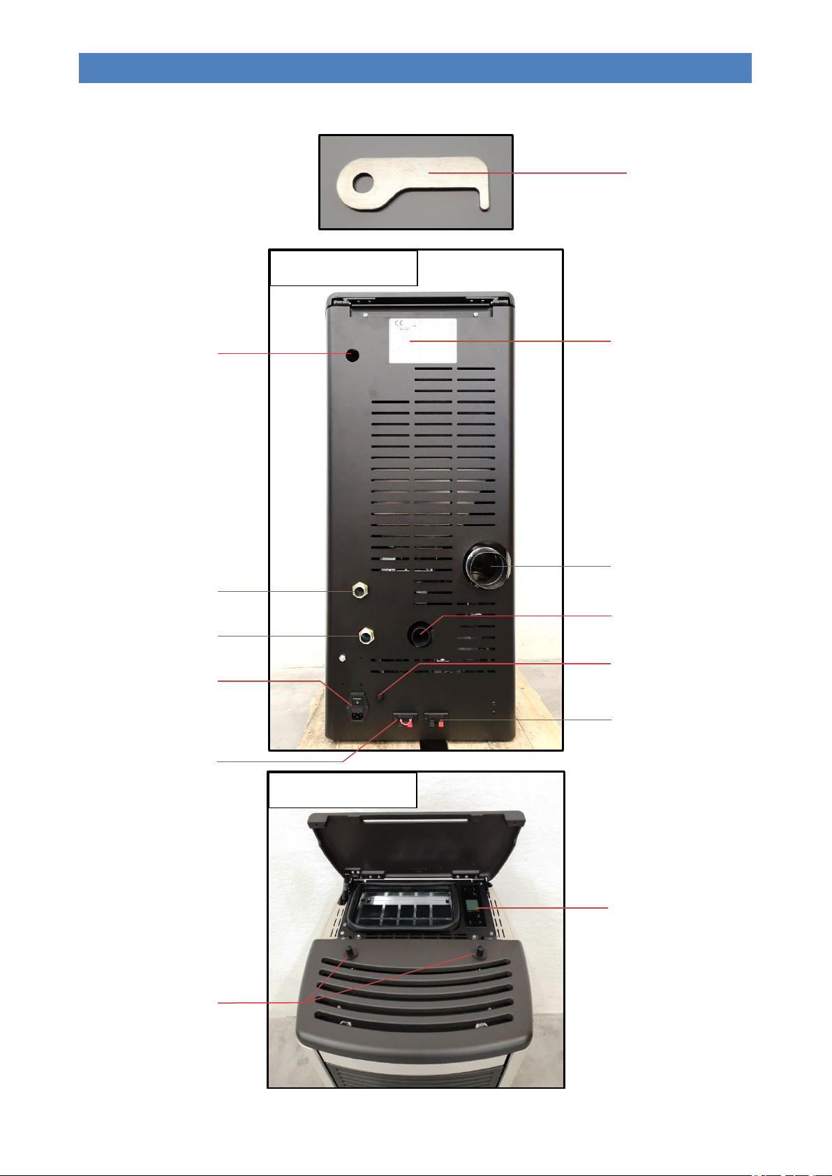
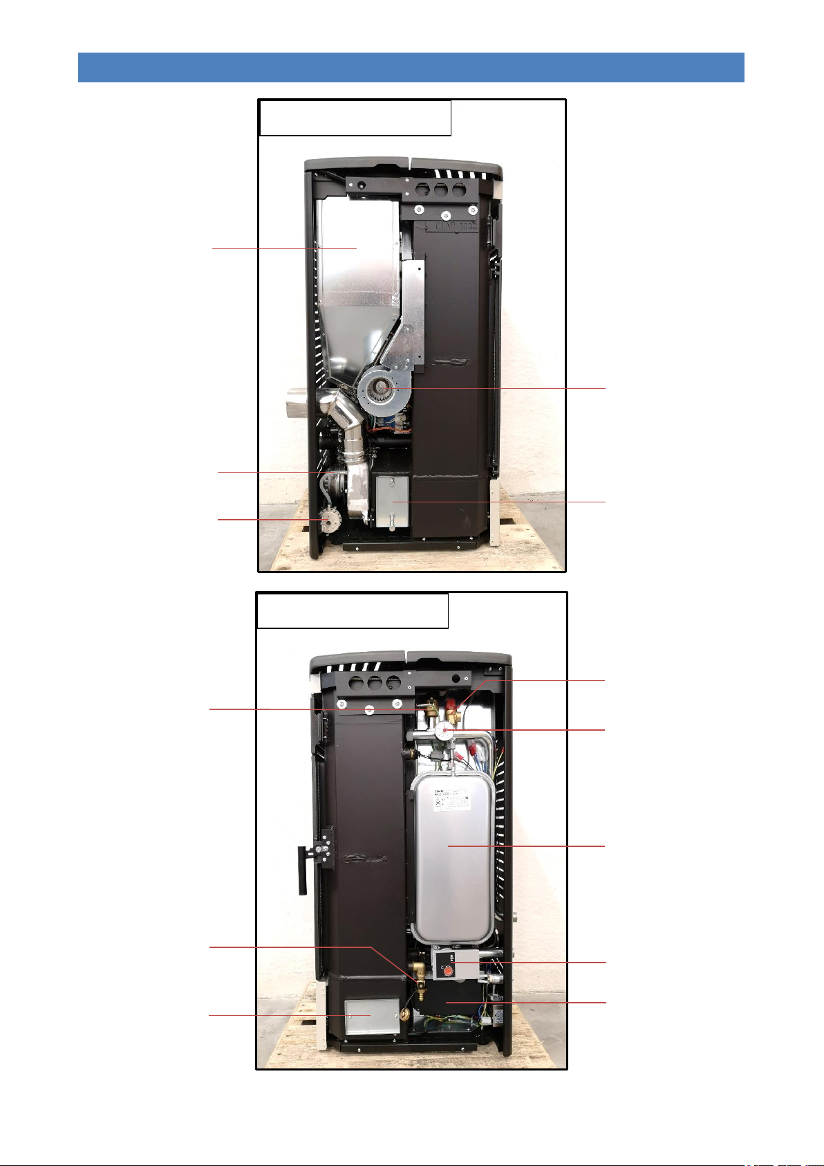
COMPONENTS OF THE APPLIANCE................................................................................................................................................................4
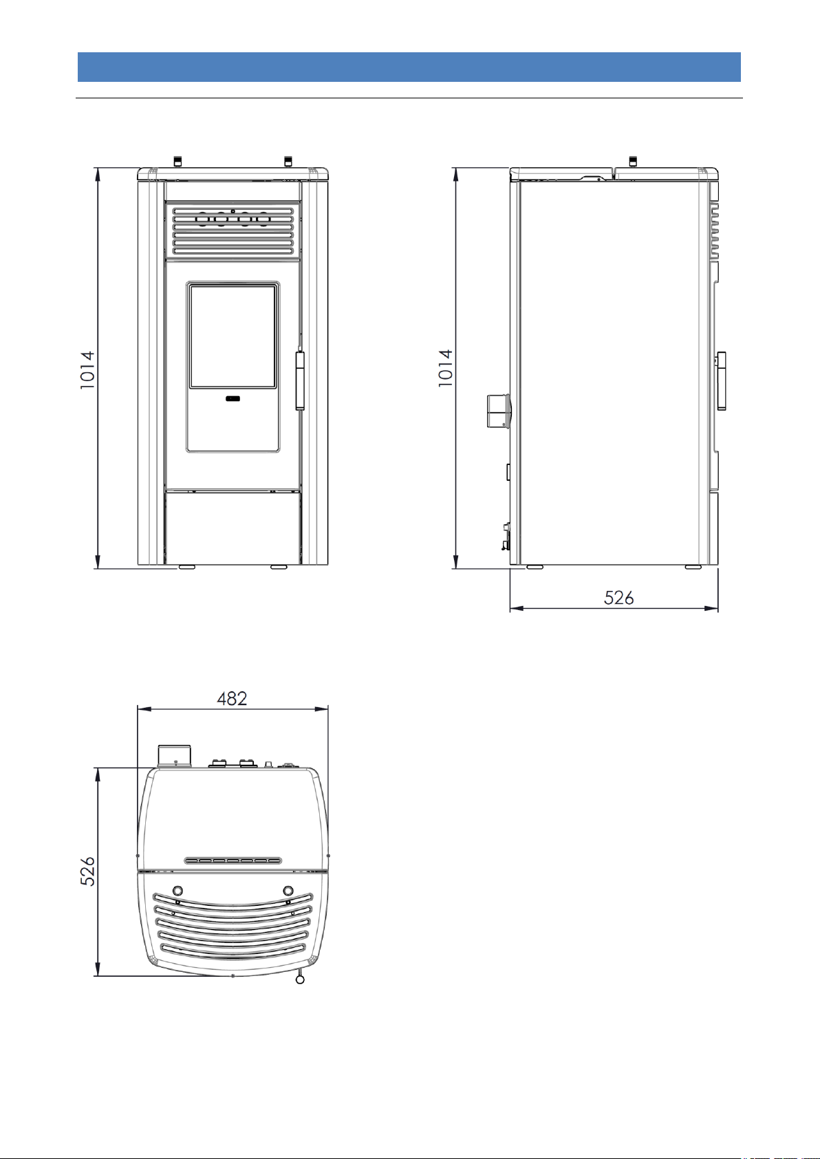
OVERALL DIMENSIONS FOR HRV VIKTOR...................................................................................................................................................7
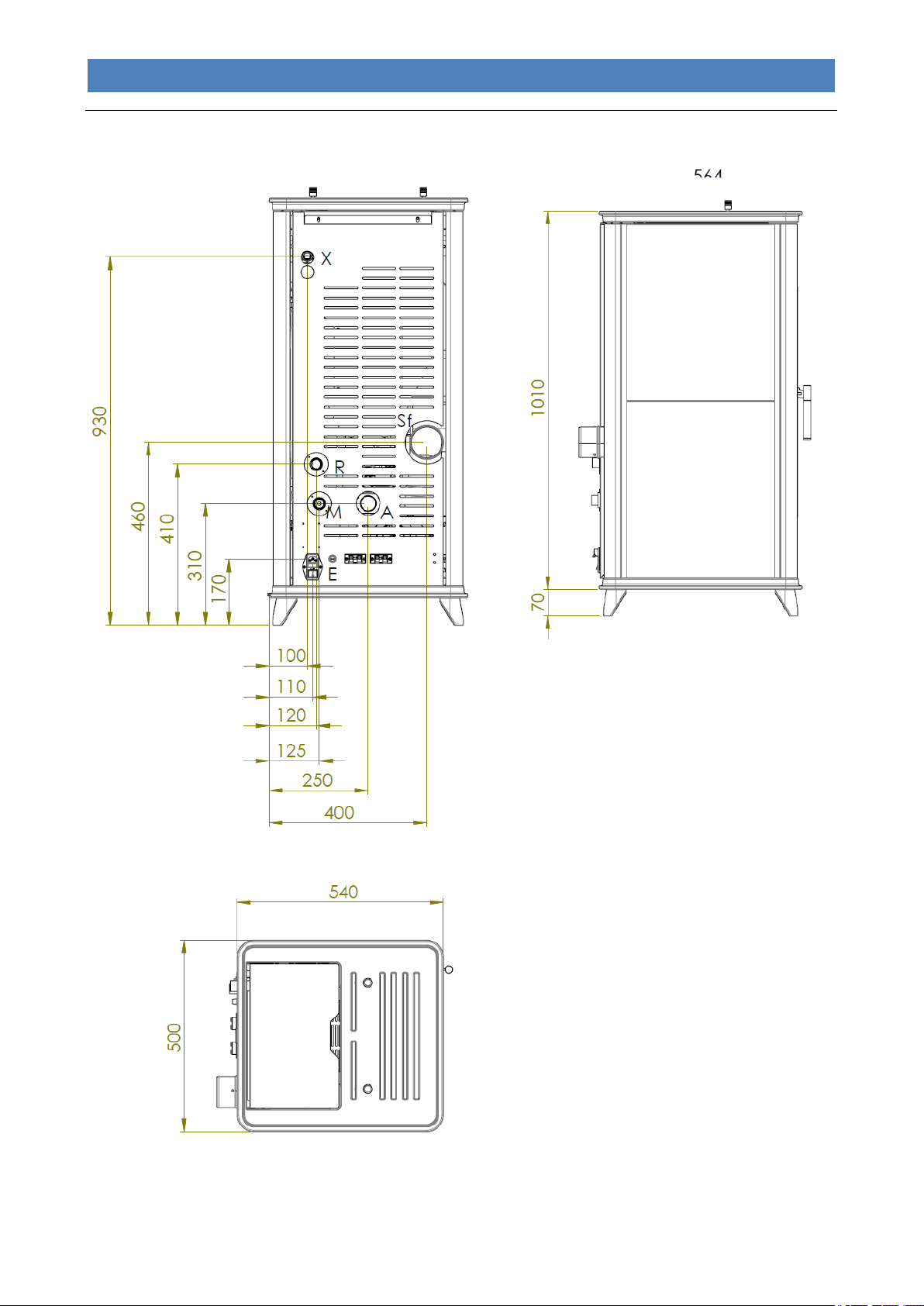
OVERALL DIMENSIONS FOR HRV TORSBY....~............................................................................................................................................8
CONNECTIONS DATA SHEET FOR HRV VIKTOR...........................................................................................................................................9
CONNECTIONS DATA SHEET FOR HRV TORSBY.... ....................................................................................................................................10
TECHNICAL SPECIFICATIONS.....................................................................................................................................................................11
PELLET PROPERTIES ................................................................................................................................................................................12
REQUIREMENTS OF THE PLACE OF INSTALLATION ................................................................................................. 12
POSITIONING ...........................................................................................................................................................................................12
SPACES AROUND AND ABOVE THE APPLIANCE.............................................................................................................................................13
EXTERNAL AIR INTAKE ..............................................................................................................................................................................13
THE FLUE AND CONNECTION TO THE SAME .................................................................................................................................................14
CHIMNEY.................................................................................................................................................................................................15
ELECTRICAL CONNECTION .......................................................................................................................................... 16
CONTROL OF ANY COUPLED BOILER...........................................................................................................................................................16
CONTROL OF A POSSIBLE THREE-WAY MOTORIZED VALVE FOR DHW SYSTEM MANAGEMENT ..........................................................................17
CONNECTION TO THE ROOM THERMOSTAT..................................................................................................................................................17
HYDRAULIC CONNECTION ............................................................................................................................................ 18
THE DISPLAY .................................................................................................................................................................. 19
THE MENU ....................................................................................................................................................................... 21
INITIAL START-UP .......................................................................................................................................................... 25
SYSTEM CONFIGURATION..........................................................................................................................................................................25
INITIAL FILLING OF THE SYSTEM .................................................................................................................................................................27
PELLET LOADING AND CONNECTION TO THE MAINS POWER SUPPLY ..............................................................................................................27
IGNITION CYCLE .......................................................................................................................................................................................27
SWITCH-OFF CYCLE..................................................................................................................................................................................28
MODIFYING THE WORKING POWER.............................................................................................................................................................28
CHANGING THE WATER TEMPERATURE BOILER OR PUFFER ..........................................................................................................................28
CHANGING THE AIR FAN SPEED..................................................................................................................................................................29
PROBLEMS, ALARMS, USEFUL TIPS ........................................................................................................................... 30
USEFUL INFO…........................................................................................................................................................................................30
WHAT HAPPENS IF…................................................................................................................................................................................30
ALARM SIGNALS .......................................................................................................................................................................................31
CLEANING AND MAINTENANCE ................................................................................................................................... 32
PRECAUTIONS BEFORE CLEANING..............................................................................................................................................................32
ROUTINE CLEANING..................................................................................................................................................................................32
NON-ROUTINE CLEANING ..........................................................................................................................................................................33
ANNUAL CLEANING ...................................................................................................................................................................................35
CLEANING THE CERAMIC GLASS.................................................................................................................................................................37
CLEANING THE FLUE.................................................................................................................................................................................37
MAINTENANCE .........................................................................................................................................................................................37
PCB PARAMETERS ........................................................................................................................................................ 38
PARAMETERS TABLE.................................................................................................................................................................................38
WIRING DIAGRAM ........................................................................................................................................................... 40
STANDARD WARRANTY CONDITIONS ......................................................................................................................... 41

PELLET BOILER STOVE HRV VIKTOR / HRV TORSBY
2
EN - Rev. 1.0
Dear client,
First of all we would like to thank you for choosing a “NORDIC FIRE” product and we hope you will be satisfied with this
product.
Carefully read the manual and warranty certificate on the last page of this User guide.
In thanking you again for the trust accorded to us, we wish to inform you that these models are the result of forty years
of experience in the manufacture of solid fuel products using water as the heat transfer fluid.
Every single detail of the product is manufactured by qualified staff, using the most advanced equipment.
The manual contains a detailed description of the appliance and its operation, instructions for proper installation, basic
maintenance and control points, which must be periodically performed; furthermore it contains practical advice which
helps to obtain maximum performance from the appliance with minimum fuel consumption.
Stay warm with NORDIC FIRE!
Copyright
All rights reserved. The reproduction of any part of this manual, in any form, without the explicit written permission of
NORDIC FIRE bv is forbidden. The content of this manual may be modified without notice. Although the documentation
contained in this manual has been carefully compiled and checked, NORDIC FIRE bv cannot be held liable for any
damages arising from the use of the same.
Copyright © 2019 NORDIC FIRE bv

PELLET BOILER STOVE HRV VIKTOR / HRV TORSBY
3
EN - Rev. 1.0
INTRODUCTION
Important safety instructions
Please read these instructions before installing and using the product.
-The installation and initial start-up of the appliance must be performed by skilled personnel trained in the relevant
safety standards. They will be responsible for the definitive installation of the appliance and its proper operation. HRV
VIKTOR / HRV TORSBY BV shall not be held liable if these precautions are not observed.
-During the installation and use of the appliance, all local regulations - including those referring to national and
European Standards - must be observed.
-Connect the flue gas outlet to a flue with the specifications described in the “Flue and its connection” section of this
User guide.
-The appliance is not suitable for installation on a shared flue system.
-If the flue should catch fire, use appropriate fire extinguishing equipment or call the fire brigade.
-Connect the product to an earthed power socket. Avoid using sockets controlled by switches or automatic timers.
-Do not use the power supply cable if damaged or worn.
-If a multiple socket is used, make sure that the total voltage of the connected devices does not exceed the rated
voltage for the socket. Also make sure that the total voltage of all the devices connected to the socket does not
exceed the maximum permitted level.
-The plug on the appliance’s power cable should be connected only once the assembly and installation of the
appliance is complete. It should remain accessible after installation if the appliance is not fitted with a suitable and
accessible two-pole switch.
-Do not use flammable substances to clean the appliance or its parts.
-Do not leave flammable containers and substances in the place where the appliance is installed.
-The appliance works exclusively with wood pellets and only with the hearth door shut.
-NEVER open the appliance’s door during normal operation and avoid using it when the glass is broken or cracked.
-The use of poor-quality pellets or any other material can damage the appliance’s functions besides voiding the
warranty and exempting the manufacturer from all liability.
-Do not use the appliance as an incinerator or for any use other than that for which it was designed.
-Do not use fuels other than those recommended.
-Do not use liquid fuels.
-The appliance, and its outer surfaces in particular, become very hot to the touch during operation; handle with caution
in order to avoid burns.
-Keep fuel and flammable materials at a safe distance.
-Only use original spare parts recommended by the manufacturer.
-Do not make any unauthorised modifications to the appliance.
-Do not touch the hot components of the product (ceramic glass, flue pipe) during normal operation.
-Never touch the appliance if you are barefoot and/or if you have wet or damp parts of the body.
-Use the appropriate button to switch off the electrical panel. Do not disconnect the power supply cable while the
appliance is operating.
-Switch the appliance off in case of a fault or malfunctions.
-During the ignition phase and normal operation of the appliance, maintain the necessary safety distance and do not
remain standing in front of it.
-Keep children away from the appliance when it is running since they could get burned by touching its hot
components.
-Do not leave the packaging elements within reach of children or unassisted disabled persons.
-Children and inexperienced people must not be allowed to use the appliance.
-The appliance may be used by children no younger than 8 years of age and people with reduced physical, sensory or
mental capabilities, or those without experience of the appliance, as long as they are supervised or have received
instructions on how to use the appliance safely and understand the hazards inherent to the appliance.
-Children should not play with the appliance.
-User maintenance and cleaning operations should not be carried out by unsupervised children.
-Clean the appliance only when it is cold.
-Clean the brazier whenever the ignition fails and nonetheless at least once a week.
-Do not use the appliance in ways other than those indicated in this user guide.
-The appliance is designed for indoor use only.

PELLET BOILER STOVE HRV VIKTOR / HRV TORSBY
4
EN - Rev. 1.0
-The appliance is designed for heating water and should therefore be connected to a plumbing system (radiators,
under-floor heaters, etc.). This system should be suitably designed and sized to distribute the power generated by
the appliance.
-This user guide constitutes an integral part of the appliance. If the product is sold to another user, this manual must
be passed on to the new owner.
Nordic Fire BV DECLINES ALL LIABILITY IN CASE OF ACCIDENTS DUE TO FAILURE TO COMPLY WITH THE
SPECIFICATIONS OF THIS MANUAL.
Nordic Fire BV DECLINES ALL LIABILITY DUE TO INCORRECT USE OF THE PRODUCT BY THE USER,
UNAUTHORISED MODIFICATION AND/OR REPAIRS, AND USE OF NON-ORIGINAL SPARE PARTS OR SPARE
PARTS NOT SPECIFICALLY DESIGNED FOR USE ON THIS PRODUCT MODEL.
Nordic Fire BV SHALL NOT BE HELD LIABLE FOR THE STOVE'S INSTALLATION. THE INSTALLER IS THE SOLE
PARTY RESPONSIBLE FOR THIS OPERATION AND IS ALSO ENTRUSTED WITH CHECKING THE FLUE,
EXTERNAL AIR VENT AND THE CORRECTNESS OF THE PROPOSED INSTALLATION SOLUTIONS. ALL THE
SAFETY REGULATIONS SET OUT IN THE SPECIFIC LAWS IN FORCE IN THE COUNTRY WHERE THE MACHINE
IS INSTALLED MUST BE OBSERVED.
NON-ROUTINE MAINTENANCE MUST ONLY BE PERFORMED BY AUTHORISED AND QUALIFIED STAFF.
To ensure the validity of the warranty, the user must comply with the instructions contained in this guide and, in
particular, must:
-Use the appliance within its operating limits;
-Regularly perform all maintenance activities;
-Authorise expert and competent people to use the appliance.
Failure to comply with the instructions contained in this guide shall automatically void the warranty.
THE MACHINE AND THE PELLETS
Components of the appliance
The table below shows the standard features of the appliance:
Expansion tank
8 l
Safety valve
2.5 bar
Pressure gauge
0 – 4 bar
Automatic air vent valve
No
Automatic air vent valve
Yes
Heating system pump
Yes. Mod.25/70
Electrical setting for boiler / puffer sensor
Yes
Remote control
Optional
Wi-Fi management module
Optional
The appliance is delivered with the following equipment:
-1 user, installation and maintenance guide;
-1 power supply cable;
-1 cleaning hook for the front heat exchanger;
-1 conventional warranty certificate.

PELLET BOILER STOVE HRV VIKTOR / HRV TORSBY
5
EN - Rev. 1.0
The images below show certain details of the appliance:
Delivery pipe.
Return pipe.
Display.
Opening
for optional connection to
safety valve.
Hook for cleaning the
front heat exchanger.
REAR VIEW
TOP VIEW
Intake pipe.
Flue gas
outlet.
R.T. terminal for room
thermostat connection.
Anti-interference filter.
Main switch, connection for
power supply cable with 2
built-in fuses (4A 250V).
Safety thermostat with
manual reset.
Terminal
for optional connection to
puffer / boiler probe.
CE label
with technical data, serial
number and model.
Upper knobs
for cleaning internal flue
gas turn.

PELLET BOILER STOVE HRV VIKTOR / HRV TORSBY
6
EN - Rev. 1.0
Pressure gauge.
High-efficiency pump
with speed selector.
Safety valve
(2.5 bar).
Boiler unit drain
cock.
Control unit.
Flue pressure switch.
Flue gas intake device.
Pellet tank.
Front fan for hot air.
Overpressure valve.
RIGHT SIDE VIEW
LEFT SIDE VIEW
Flue gas turn side
inspection plate.
Expansion tank
8 l with pre-load 1 bar.
Automatic air vent
valve (jolly).

PELLET BOILER STOVE HRV VIKTOR / HRV TORSBY
7
EN - Rev. 1.0
Overall dimensions for HRV VIKTOR

PELLET BOILER STOVE HRV VIKTOR / HRV TORSBY
8
EN - Rev. 1.0
Overall dimensions for HRV TORSBY

PELLET BOILER STOVE HRV VIKTOR / HRV TORSBY
9
EN - Rev. 1.0
Connections data sheet for HRV VIKTOR
Description of connections
M= System Delivery
3/4" M
R= System Return
3/4" M
X= Safety valve drain
1/2" F
Sf= Rear flue gas outlet
80 mm M
A = Intake pipe
40 mm
E = Electricity connection
REAR VIEW

PELLET BOILER STOVE HRV VIKTOR / HRV TORSBY
10
EN - Rev. 1.0
Connections data sheet for HRV TORSBY
Description of connections
M= System Delivery
3/4" M
R= System Return
3/4" M
X= Safety valve drain
1/2" F
Sf= Rear flue gas outlet
80 mm M
A = Intake pipe
40 mm
E = Electricity connection
REAR VIEW

Declaration of performance / Prestatieverklaring
Leistungserklärung / Déclaration des performances
According to Regulation (EU) 305/201 / Conform regeling (EU) 305/2011
Gemass der Verordnung (EG) nr. 305/2011 / Conformément au règlement (EU) nr. 305/2011
1. Number of the declaration of performance / Uniek
nummer prestatieverklaring / Nummer Leistungserklärung /
Numéro déclaration des performances
Unique identification product-type / Uniek identificatiecode producttype /
Eindeutiger Kenncode de Produckttyp / Code d'identification unique du
produit typ
Type, batch or serialnr. / Type-, partij- of serienummer / Typen-,
Chargen- oder Seriennummer / Numéro de type, de lot ou de sèrie
Intended use of product / Beoogd gebruik van product /
Bestimmungsgemäße Verwendung des Produkts / Utilisation prévue du
produit
Contact address of the manufacturer / Contactadres van de fabrikant /
Kontaktadresse des Herstellers / Adresse de contact du fabricant
System or systems of assessment and verification of constancy of
performance of the construction product as set out in Annex V / Het
systeem of de systemen voor de beoordeling en verificatie van de
prestatiebestendigheid van het bouwproduct vermeld in Bijlage V /
Systeme zur Bewertung und Kontrolle de Konstanz der
Leistungsfähigkeit de Bauprodukts (AVCP) / Le ou les systèmes
d’évaluation et de vérification de la constance des performances du
produit de construction, conformément à l’annexe V
Notified Body / Keuringsinstantie / Notifiziertes Labor / Laboratoire notifié
Test rapport number / Testrapportnummer / Numéro du rapport de test
2. Declared performance / Aangegeven prestatie
Erklärte Leistung / Performance déclarées
Description / Beschrijving / Beschreibung / Description
Fire safety / Brandveiligheid / Brandwiderstand / Sécurité incendie
Distance to combustible materials / Afstand tot brandbare
materialen / Abstand zu brennbaren Materialien / Distance
minimale à respecter par rapport aux matériaux combustibles
adjacents
Minimum distances / Minimum afstanden /
Mindestabastände / Distance minimale
Performance / Prestatie / Leistung / Performances
Rear / Achterzijde /
Hinten / Arrière
Sides / Zijkanten /
Seiten / Côtés
Front / Voorzijde /
Vorseite / Defant
Pass / Voldoet /
Bestanden / Conforme
Risk of burning fuel falling out / Risico op eruit vallen van
brandende brandstof / Gefahr durch Herausfallen von
brennendem Heizmaterial / Risque de projections de braises
EN 14785
mm
mm
mm
1 / 2
C-613
HRV Viktor
HVTR
Residental space heating appliance fuel by wood
pellets / Product om woonruimte verwarmen
middels stoken pellets / Gerät zum Heizen von
Haushalten mit Holzpellets / Appareil de
chauffage domestique alimenté au granulés de
bois
Nordic Fire B.V.
De Immenhorst 5
7041 KE 's Heerenberg
The Netherlands
System 3 / Systeem 3 / System 3 / Système 3
KIWA CERMET ITALY s.p.a.
2003474
200
200
800

Pa
Pass / Voldoet /
Bestanden / Conforme
T (°C]
kW
kW
kW
The efficiency of the above product corresponds to the declared performance. The above-mentioned manufacturer is solely
responsible for drawing up the declaration of performance in accordance with the Regulation (EU) no. 305/2011.
De prestaties van bovenstaand product komen met de verklaring overeen. Voor de opstelling van de prestatieverklaring
overeenkomstig verordening (EU) Nr. 305/2011 is alleen de bovengenoemde fabrikant verantwoordelijk.
Die Leistung des vorstehenden Produkts entspricht der erklärten Leistung/den erklären Leistungen. Für die Erstellung der
Leistungserklärung im Einklang mit der Verordnung (EU) Nr. 305/2011 ist allein der obengenannte Hersteller verantwortlich.
La performance du produit susmentionné est conforme à la performance déclarée/aux performances déclarées.
L‘établissement de la déclaration de performance conformément au règlement UE n° 305/2011 est la seule responsabilité
du fabricant susmentionné.
Signed for and on behalf of the manufacturer by:
Ondertekend namens de fabrikant door:
Unterschreibe für und im Namen des Herstellers von:
Signé au nom du fabricant par:
T. Wanders, Managing Director
Chimney draft / Schoorsteentrek / Förderdruck / Tirage de cheminée
Flue gas mass / Rookgasmassa / Abgasmassenstrom / Masse
des fumées
Cleanability / Reinigbaarheid verbrandingskamer / Reinigung /
Possibilités de nettoyage
Flue gas temperature at nominal heat output / Rookgastemperatuur bij
nominaal vermogen / Rauchgastemeratur bei nomineller Heizleistung /
Température des fumées dans le conduit de raccordement en
fonctionnement nominal
Nominal heat output / Nominaal vermogen / Nominelle Leistung /
Puissance nominale
Vermogen
%
Minimal heat output / Minimaal vermogen / Puissance minimale /
Minimale Leistung
Water heating output / Waterzijdig vermogen / Leistung
Wassererwärmung / Puissance de chauffage de l'eau
Energy efficiency / Rendement / Wirkungsgrad / Rendement
g/s
CO ( % )
Emission of combustion products / Emissie van
verbrandingsproducten / Emission von Verbrennungsprodukten /
Émissions provenant de la combustion
Description / Beschrijving / Beschreibung / Description Performance / Prestatie / Leistung / Performances
EN 14785
2. Declared performance (continuation) / Aangegeven prestatie (vervolg)
Erklärte Leistung (Folge) / Performance déclarées (suite)
Dust (mg/Nm3 13% O2)
Fijnstof (mg/Nm3 13% O2)
Staub (mg/Nm3 13% O2)
poussière (mg/Nm3 13% O2)
Declaration of performance / Prestatieverklaring
Leistungserklärung / Déclaration des performances
2 / 2
0.009
14.03
12.1
8.9
80.0
15.0
3.3
11.7
95.9
15-09-2020

Declaration of performance / Prestatieverklaring
Leistungserklärung / Déclaration des performances
According to Regulation (EU) 305/201 / Conform regeling (EU) 305/2011
Gemass der Verordnung (EG) nr. 305/2011 / Conformément au règlement (EU) nr. 305/2011
1. Number of the declaration of performance / Uniek
nummer prestatieverklaring / Nummer Leistungserklärung /
Numéro déclaration des performances
Unique identification product-type / Uniek identificatiecode producttype /
Eindeutiger Kenncode de Produckttyp / Code d'identification unique du
produit typ
Type, batch or serialnr. / Type-, partij- of serienummer / Typen-,
Chargen- oder Seriennummer / Numéro de type, de lot ou de sèrie
Intended use of product / Beoogd gebruik van product /
Bestimmungsgemäße Verwendung des Produkts / Utilisation prévue du
produit
Contact address of the manufacturer / Contactadres van de fabrikant /
Kontaktadresse des Herstellers / Adresse de contact du fabricant
System or systems of assessment and verification of constancy of
performance of the construction product as set out in Annex V / Het
systeem of de systemen voor de beoordeling en verificatie van de
prestatiebestendigheid van het bouwproduct vermeld in Bijlage V /
Systeme zur Bewertung und Kontrolle de Konstanz der
Leistungsfähigkeit de Bauprodukts (AVCP) / Le ou les systèmes
d’évaluation et de vérification de la constance des performances du
produit de construction, conformément à l’annexe V
Notified Body / Keuringsinstantie / Notifiziertes Labor / Laboratoire notifié
Test rapport number / Testrapportnummer / Numéro du rapport de test
2. Declared performance / Aangegeven prestatie
Erklärte Leistung / Performance déclarées
Description / Beschrijving / Beschreibung / Description
Fire safety / Brandveiligheid / Brandwiderstand / Sécurité incendie
Distance to combustible materials / Afstand tot brandbare
materialen / Abstand zu brennbaren Materialien / Distance
minimale à respecter par rapport aux matériaux combustibles
adjacents
Minimum distances / Minimum afstanden /
Mindestabastände / Distance minimale
Performance / Prestatie / Leistung / Performances
Rear / Achterzijde /
Hinten / Arrière
Sides / Zijkanten /
Seiten / Côtés
Front / Voorzijde /
Vorseite / Defant
Pass / Voldoet /
Bestanden / Conforme
Risk of burning fuel falling out / Risico op eruit vallen van
brandende brandstof / Gefahr durch Herausfallen von
brennendem Heizmaterial / Risque de projections de braises
EN 14785
mm
mm
mm
1 / 2
C-612
HRV Torsby
HTRB
Residental space heating appliance fuel by wood
pellets / Product om woonruimte verwarmen
middels stoken pellets / Gerät zum Heizen von
Haushalten mit Holzpellets / Appareil de
chauffage domestique alimenté au granulés de
bois
Nordic Fire B.V.
De Immenhorst 5
7041 KE 's Heerenberg
The Netherlands
System 3 / Systeem 3 / System 3 / Système 3
KIWA CERMET ITALY s.p.a.
2003474
200
200
800

Pa
Pass / Voldoet /
Bestanden / Conforme
T (°C]
kW
kW
kW
The efficiency of the above product corresponds to the declared performance. The above-mentioned manufacturer is solely
responsible for drawing up the declaration of performance in accordance with the Regulation (EU) no. 305/2011.
De prestaties van bovenstaand product komen met de verklaring overeen. Voor de opstelling van de prestatieverklaring
overeenkomstig verordening (EU) Nr. 305/2011 is alleen de bovengenoemde fabrikant verantwoordelijk.
Die Leistung des vorstehenden Produkts entspricht der erklärten Leistung/den erklären Leistungen. Für die Erstellung der
Leistungserklärung im Einklang mit der Verordnung (EU) Nr. 305/2011 ist allein der obengenannte Hersteller verantwortlich.
La performance du produit susmentionné est conforme à la performance déclarée/aux performances déclarées.
L‘établissement de la déclaration de performance conformément au règlement UE n° 305/2011 est la seule responsabilité
du fabricant susmentionné.
Signed for and on behalf of the manufacturer by:
Ondertekend namens de fabrikant door:
Unterschreibe für und im Namen des Herstellers von:
Signé au nom du fabricant par:
T. Wanders, Managing Director
Chimney draft / Schoorsteentrek / Förderdruck / Tirage de cheminée
Flue gas mass / Rookgasmassa / Abgasmassenstrom / Masse
des fumées
Cleanability / Reinigbaarheid verbrandingskamer / Reinigung /
Possibilités de nettoyage
Flue gas temperature at nominal heat output / Rookgastemperatuur bij
nominaal vermogen / Rauchgastemeratur bei nomineller Heizleistung /
Température des fumées dans le conduit de raccordement en
fonctionnement nominal
Nominal heat output / Nominaal vermogen / Nominelle Leistung /
Puissance nominale
Vermogen
%
Minimal heat output / Minimaal vermogen / Puissance minimale /
Minimale Leistung
Water heating output / Waterzijdig vermogen / Leistung
Wassererwärmung / Puissance de chauffage de l'eau
Energy efficiency / Rendement / Wirkungsgrad / Rendement
g/s
CO ( % )
Emission of combustion products / Emissie van
verbrandingsproducten / Emission von Verbrennungsprodukten /
Émissions provenant de la combustion
Description / Beschrijving / Beschreibung / Description Performance / Prestatie / Leistung / Performances
EN 14785
2. Declared performance (continuation) / Aangegeven prestatie (vervolg)
Erklärte Leistung (Folge) / Performance déclarées (suite)
Dust (mg/Nm3 13% O2)
Fijnstof (mg/Nm3 13% O2)
Staub (mg/Nm3 13% O2)
poussière (mg/Nm3 13% O2)
Declaration of performance / Prestatieverklaring
Leistungserklärung / Déclaration des performances
2 / 2
0.009
14.03
12.1
8.9
80.0
15.0
3.3
11.7
95.9
15-09-2020

PELLET BOILER STOVE HRV VIKTOR / HRV TORSBY
11
EN - Rev. 1.0
Technical Specifications
Heat input (nominal setting)
kW (Kcal/h)
15.6 (13,420)
Heat input (reduced setting)
kW (Kcal/h)
4.4 (3,780)
Nominal thermal output
kW (Kcal/h)
15.0 (12,900)
Reduced thermal power
kW (Kcal/h)
4.3 (3,700)
Nominal heat output ceded to water
kW (Kcal/h)
11.7 (10,060)
Nominal heat output ceded to the environment
kW (Kcal/h)
3.3 (2,840)
Reduced heat output ceded to water
kW (Kcal/h)
3.0 (2,580)
Reduced heat output ceded to the environment
kW (Kcal/h)
1.3 (1,120)
Combustion efficiency at nominal thermal power
%
95.9
Combustion efficiency at reduced thermal power
%
96.8
CO at 13% oxygen at nominal thermal power
%
0.007
CO at 13% oxygen at reduced thermal power
%
0.038
Maximum power uptake
Watt
400*
Power uptake during operation at nominal thermal power
Watt
56
Power uptake during operation at reduced thermal power
Watt
14
Power uptake in stand-by
Watt
3.0
Nominal voltage
V
230
Nominal frequency
Hz
50
Expansion vessel litres/preloading bar
6 / 1
Maximum operating/recommended pressure
bar
2.5 / 1.5
Flue outlet diameter
mm
80
Air intake pipe diameter
mm
40
Minimum chimney draught at nominal thermal power
Pa
12.1
Minimum chimney draught at reduced power
Pa
7.7
Combustion gas mass at nominal thermal power
g/s
8.9
Combustion gas mass at reduced power
g/s
4.1
Pellet tank capacity
Kg
20
Average exhaust flue gas temperature at nominal thermal power
°C
80.0
Average exhaust flue gas temperature at reduced power
°C
49.4
Boiler unit capacity
litres
15
Width
mm
520
Height
mm
1100
Depth
mm
480
Minimum safety distance from flammable materials
(side / rear / upper / front)
mm
200 / 200 / 750 / 800
Weight
Kg
145
* Power consumption only during the ignition cycle.
The appliance's heat output may vary depending on the type of pellets used.

PELLET BOILER STOVE HRV VIKTOR / HRV TORSBY
12
EN - Rev. 1.0
Pellet properties
The appliance has been tested with all types of pellets available on the market. The pellets must have the following
properties:
-Diameter 6 mm.
-Maximum length 35 mm.
-Maximum humidity content 8 –9 %.
-100% wood. Totally additive-free.
-Maximum ash residue 1.1 %.
To obtain good performance from the appliance, we recommend using good quality pellets. Pellets should be poured
into the tank using a shovel, and not directly from the bag.
Good quality pellets should have the following properties:
-Constant diameter cylinders with a smooth, shiny surface;
-There should not be a lot of sawdust inside the packaging;
-After grabbing a bunch of pellets and placing them into a container filled with water, good-quality pellets will sink and
poor-quality ones will tend to float;
-The quality certification data, in particular conformity to international standards such as EN14961-2, DIN 51731 and
O-NORM M7135, should be indicated on the packaging;
-The packages should be intact since pellets tend to absorb humidity. Humidity not only reduces the calorific value
and increases the amount of flue gases expelled, but also causes swelling of the product which may create problems
with the appliance.
The production of pellets must be compliant with some international standards (such as EN14961-2, DIN 51731 and O-
NORM M7135) which establish minimum values for quality checks on pellets. To facilitate the right choice of the
combustible material you can find below one of the most common certification marks identifying the quality of the pellets:
The use of poor quality pellets or any other material can damage the appliance operation, voiding the warranty
and exempting the manufacturer from all liability.
In order to guarantee trouble-free combustion, the pellets must be stored in a dry place.
REQUIREMENTS OF THE PLACE OF INSTALLATION
Positioning
The initial phase for best installation of the appliance is to determine its optimum location; the following elements need to
be considered:
-The possibility of creating an external air vent;
-The possibility of creating a straight flue, preferably coaxial to the outlet of the appliance;
-Proximity to the main water drain and/or the boiler (if one already exists);
-Proximity or ease of connection to the water system;
-Ease of access for cleaning the appliance, the flue gas exhaust pipes and the flue.
Indication of the standard,
base reference for the quality
classes ENplus
Indication of the quality
class of the certified pellet
(preferable A1)
IT xxx
Code of the certified company
consisting of two elements:
-Symbol of the country of
production (example “IT”)
-Progressive number assigned at
the acquisition of the
certification (example "xxx")

PELLET BOILER STOVE HRV VIKTOR / HRV TORSBY
13
EN - Rev. 1.0
The unit must be installed on a floor with a suitable load capacity. If the existing building does not fulfil this requirement
appropriate measures (e.g. load distribution plate) must be taken.
The minimum safety distance from flammable materials must be at least 200 mm from the sides and back of the
appliance, 800 mm from the front and 750 mm from the upper part.
The installation must guarantee easy access for cleaning the appliance, the flue gas exhaust pipes and the flue, and any
subsequent maintenance operation by the Authorised technical assistance centre.
Once you have found the best location for the appliance, position it following the instructions given below.
The appliance must not be installed in small rooms, bedrooms, bathrooms or in areas with an explosive atmosphere
(e.g. garages).
Spaces around and above the appliance
The figure below shows the minimum distances from walls or other not-easily-removable furniture, that need to be taken
into consideration when positioning the appliance.
Any shelves or false ceilings mounted above the appliance must be at least 75 cm away from the top part of it.
Furniture and movable objects made from flammable materials must be positioned at least 20 cm from the side surfaces
of the appliance; these objects must be moved when performing maintenance on the appliance.
Protect all structures that can catch fire against the radiated heat of the fire.
Any extra intervention by the Authorised technical assistance centre, which requires the appliance to be
disconnected from the system, will not be covered under warranty as described in the chapter “Standard
Warranty Conditions”.
External air intake
During operation, the appliance takes in air from the environment in which it is installed; It is therefore essential that this
air is replaced through an external air vent. The absence of the air vent may affect the flue draught and therefore the
combustion and the safety of the appliance.
Therefore it is mandatory to install an external air vent with a minimum completely free passage of at least 80 cm2
(round hole with minimum diameter of 15 cm protected with a special fixed large mesh grille).
If it not possible to put the external air vent in the same room as where the appliance is installed, this hole can be made
in an adjoining room as long as this room communicates permanently, by means of a transit hole (15 cm minimum
diameter).
The hole must be protected externally with a fixed grille. The protective grille must be checked periodically to ensure that
it is not obstructed, thereby impeding the passage of air. Therefore keep the air vents clear of obstructions.
The UNI 10683 Standard FORBIDS the drawing of combustion air from garages, warehouses storing combustible
materials, or from business premises with a fire hazard.
REARWALL
SIDE WALL
SIDE WALL

PELLET BOILER STOVE HRV VIKTOR / HRV TORSBY
14
EN - Rev. 1.0
If there are other heating or extraction devices inside the room, the air vents must guarantee a sufficient amount of air for
properly operating all the devices.
Only sealed appliances (e.g. C type gas appliances, according to the UNI 7129 Standard) or appliances that do not
cause a lower pressure compared with the external environment can pre-exist or be installed in the place where the
appliance is installed.
Extractor fans can cause malfunctions to the appliance if used in the same room.
The flue and connection to the same
The flue is an essential element for the efficient operation of the appliance. The flue must have the minimum cross-
sectional dimensions stated in the appliance’s technical specifications (80 mm). Each product must be equipped with its
own flue, without other adjoining elements (boilers, chimneys, stoves, etc.). The flue dimensions are closely related to its
height, which must be measured from the appliance flue gas outlet to the base of the stack. In order to guarantee
adequate draught, the surface of the chimney flue outlet must be double the flue cross-section. The discharge pipe for
combustion products generated by the forced draught device, must comply with the following requirements:
-It must seal off the combustion gases, as well as being waterproof and suitably isolated and insulated in relation to
the conditions of use (refer to UNI 9615);
-It must be made of suitable materials capable of withstanding normal mechanical stress, heat, and the effects of
combustion gases and condensate, if any;
-It must go upwards after the vertical section, for the entire remaining part, with a minimum gradient of 5%. The sub-
horizontal section must not have a length greater than ¼ of the effective height H of the flue or chimney, and must
not be longer than 2,000 mm;
-It must preferably have a round internal cross-section: square or rectangular cross-sections must have rounded
corners with radius not inferior to 20 mm;
-It must have a constant, free and independent internal cross section;
-Rectangular cross-sections must have a maximum ratio of 1.5 between the sides;
- It must be insulated to prevent the fumes from cooling and forming condensation;
-Parts made from non-combustible materials (it is absolutely prohibited the use of aluminium flue) - capable of
withstanding combustion gases and potential condensation - must be used for mounting the flue gas pipes (for the
section from the appliance to the flue inlet);
-It is forbidden to use fibre cement pipes to connect the appliance to the flue;
-Flue gas conduits must not pass through rooms in which the installation of combustion devices is prohibited;
-The flue gas conduits must be assembled in such a way as to guarantee adequate sealing of flue gases during low
pressure operation of the appliance;
- The installation of horizontal sections is prohibited;
- It is prohibited to use counter sloping elements;
-The flue gas pipe must allow for the recovery of soot or be cleanable, and must have a constant cross-section;
This manual suits for next models
1
Table of contents
Other NORDIC FIRE Stove manuals
Popular Stove manuals by other brands

Royal
Royal Alida Air 120 manual

Napoleon
Napoleon EPA 1100 Installation and operation instructions

Nobis
Nobis ELENA 12 V Instructions for installation, use and maintenance manual

Olsberg
Olsberg Libra instructions

Napoleon
Napoleon Bayfield GDS25N-1 Installation and operation manual

Chesney's
Chesney's Optimyst user manual

COMPANION
COMPANION COMP202 owner's manual

FRANCO BELGE
FRANCO BELGE Normandie 174 10 44 Technical manual

Limousin
Limousin 134 10 12 Technical manual

Extraflame
Extraflame Comfort Maxi user manual

Tiger
Tiger superclean Installation and operating instructions

Nordica
Nordica STEFANY Forno Instructions for installation, use and maintenance