K&G GROEP NANO MARINE User manual

www.kg-groep.com January 1, 2023 | version 1.2
Design Installation Operation Manual
NANO MARINE
FIRE DETECTION
EXTINGUISHING
CONTROL SYSTEM

Design Installation Operation Manual NANO/MAR/SYSTEM January 1, 2023 | version 1.2 P 2
TABLE OF CONTENTS
1 DOCUMENT REVISION DETAILS 3
2 SOFTWARE UPGRADE DETAILS 3
3 ABBREVIATIONS 3
4 IMPORTANT NOTES 3
5 CERTIFICATION 3
6 INTRODUCTION 4
7 ENCLOSURE & INSTALLATION 4
8 MAINTENANCE & CLEANING 4
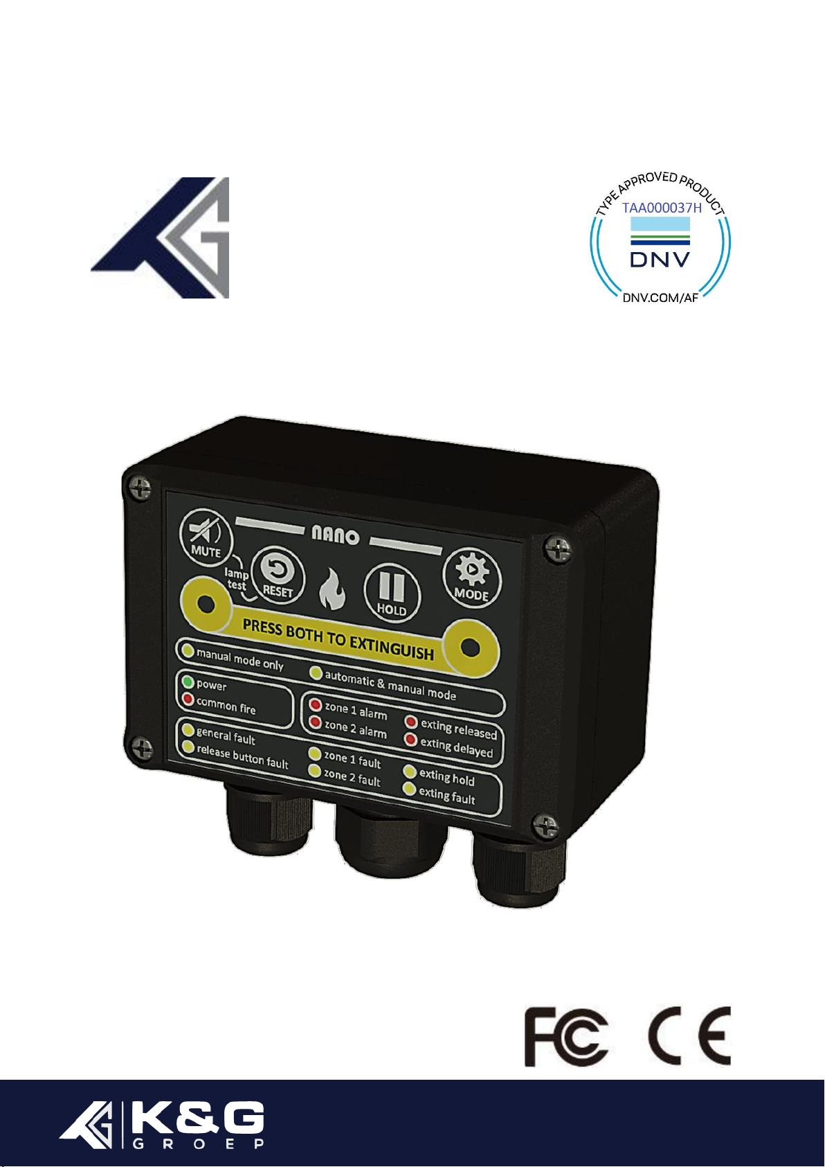
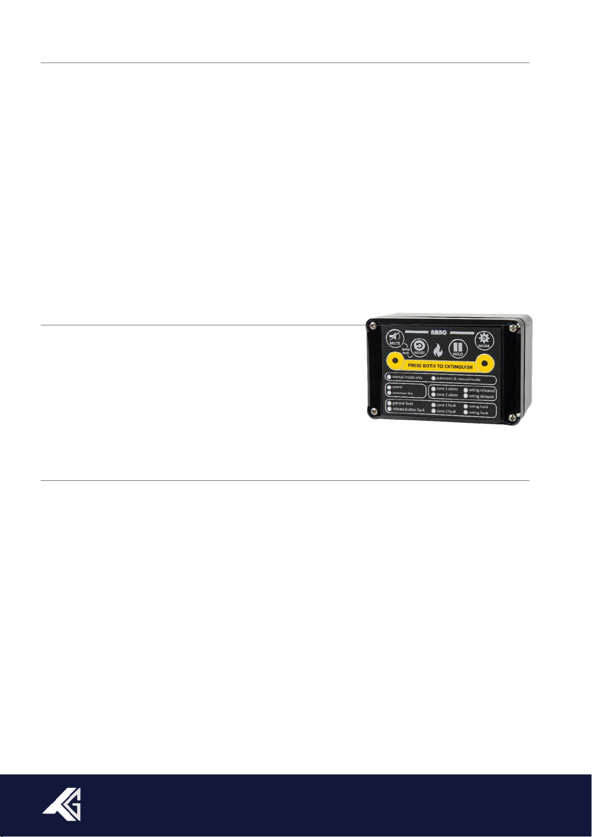
9 NANO MARINE SYSTEM 5
10 KEY PROPERTIES 6
11 FEATURES NANO/MAR/SYSTEM 6
11.1 ACOUSTIC ALARM 6
11.2 EXTINGUISHANT RELEASE OUTPUT 6
11.3 HISTORIC EVENT LOG 7
11.4 COMMUNICATION PORT 7
11.5 DIRECT RELEASE 7
11.6 VEHICLE MODE (NORMALLY NOT IN USE IN MARINE APPLICATIONS) 7
11.7 GENERAL FAULT RELAY 7
11.8 VFC FIRE RELAY IN SINGLE OF DUAL MODE 8
11.9 SINGLE OR DUAL ZONE 8
11.10 EXTINGUISHANT RELEASE DELAY 8
12 INPUTS 8
12.1 DETECTION ZONES 8
12.2 EXTERNAL RELEASE INPUT 9
12.3 EXTERNAL HOLD INPUT 9
13 OUTPUTS 9
13.1 VOLT FREE CONTACT RELAY OUTPUTS 9
13.2 MONITORED EXTINGUISHING OUTPUT 9
13.3 MONITORED SOUNDER OUTPUT 9
14 CONTROL BUTTONS 10
14.1 MUTE 10
14.2 RESET 10
14.3 LAMP TEST 10
14.4 HOLD EXTINGUISHING RELEASE 10
14.5 AUTOMATIC &MANUAL RELEASE OR MANUAL ONLY MODE 10
14.6 EXTINGUISHING RELEASE 10
15 LED INDICATORS 11
15.1 MANUAL RELEASE ONLY 11
15.2 AUTOMATIC &MANUAL RELEASE 11
15.3 POWER (PSU 1IS MAINS PSU 2IS BACKUP) 11
15.4 COMMON FIRE 11
15.5 FIRE ZONE ALARM 12
15.6 EXTINGUISHING RELEASED 12
15.7 EXTINGUISHING DELAY 12
15.8 GENERAL FAULT 12
15.9 FIRE ZONE FAULT 12
15.10 EXTINGUISHING RELEASE HOLD 12
15.11 EXTINGUISHING RELEASE FAULT 12
15.12 INTERNAL FAULT INDICATORS 12
16 DIP SWITCHES 13
16.1 SETTINGS 13
16.2 DIRECT RELEASE (PDS 1) 13
16.3 VEHICLE MODE (PDS 2) 13
16.4 EXTINGUISHING RELEASE OUTPUT (PDS 3) 13
16.5 SINGLE OR DUAL FIRE ALARM (PDS 4) 14
16.6 VFC RELAY (PDS 5) 14
16.7 EXTINGUISHING DELAY TIMER (PDS 6-7-8) 14
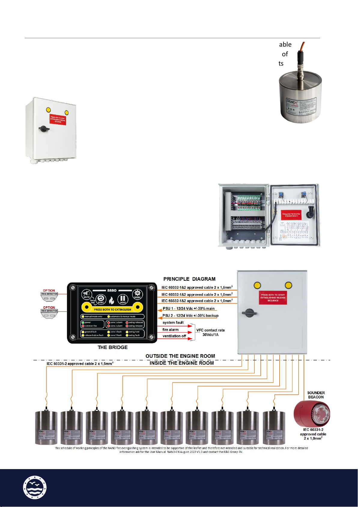
17 WIRING THE NCP AND NETB 15
18 WIRING DIAGRAM NETB 5 16
19 WIRING DIAGRAM NETB 10 17
20 CONNECTING USING THE EXTINGUISHER TERMINAL BOX (NETB) 18
21 EXAMPLE SWITCH POSITION NETB 5 WITH 3 EXTINGUISHERS 18
22 EXAMPLE SWITCH POSITION NETB 10 WITH 7 EXTINGUISHERS 19
23 THE NMS USING A SOLENOID ACTIVATOR 19
23.1 WIRING A SOLENOID ACTIVATION SYSTEM 20
24 WIRING & CABLE SPECIFICATIONS: 20
25 TECHNICAL SPECIFICATION 21
26 DEVICES SUPPORTED BY THE NMS 22
26.1 DETECTION DEVICE SUPPORT 22
26.2 SOUNDER /BEACON DEVICE SUPPORT 22
27 ENCLOSURE SPECIFICATIONS NCP 22
28 NMS FIRE DETECTOR AND WIRING OPTIONS 23
29 EXTERNAL EXTINGUISHERS RELEASE & HOLD WIRING OPTIONS 24
30 VTB-EM WIRING OPTION SOUNDER & BEACON 24
31 VTB-EM WIRING OPTION EXTENDED SOUNDER & BEACONS 25
32 WARRANTY 26
33 NOTES 27

www.kg-groep.com P 3
1DOCUMENT REVISION DETAILS
Issue
Modification Detail
Author
Date
01
1st publishing document
CvT
01 / 09 / 2022
02
DNV approval received
CvT
22 / 12/ 2022
2SOFTWARE UPGRADE DETAILS
Ver.
Modification Detail
Author
Date
02
1st release Kiwa/Dare EMC test
CvT
01 / 08 / 2022
03
Event log extend
CvT
01 / 10 / 2022
3ABBREVIATIONS
NMS NANO/MAR System
NCP NANO Control Panel
NETB NANO ETB/MAR/BOX (extinguishers terminal box)
PDS Programming Dip Switch
CP Connection Point
PSU Power Supply
VFC Volt free contact
EOL End of line device
PCB Printed circuit board
4IMPORTANT NOTES
This manual should be thoroughly read and understood before installation and/or commissioning of
the system is undertaken. The NMS is not to be regarded as properly used when it is used without
regard to any relevant information or advice relating to its use that has been made available by the
supplier. The NMS and the associated connections must be installed, commissioned, and maintained
by a skilled, knowledgeable, and competent person or organization that is qualified to perform this
work and is familiar with the objective of the equipment and the associated technical terminology.
This equipment is not guaranteed unless the complete installation is installed and commissioned in
accordance with the laid down local and/or national standards.
5CERTIFICATION
The NMS has successfully passed CE and FCC, EMC testing according to EN 50130, EN 61000, EN
55016, 47 CFR15-ICES-003, ANSI 63.4, IEC60945-pt11 and a DNV marine type approval according the
DNV Class Guideline 0339-2021, certificate TAA000037H. For that the NMS has endured extensive
environmental tests such as vibration, dry heat, damp heat and cold tests in accordance with the
requirements of the DNV-CG 0339 standard.

Design Installation Operation Manual NANO/MAR/SYSTEM January 1, 2023 | version 1.2 P 4
6INTRODUCTION
The purpose of this document is to describe installation, service and troubleshooting of the NMS.
Please note that only aspects regarding the NMS itself are covered by this manual. Physical placement
of aerosol generators and cables etc. is not handled as these issues are typically to be specified
specifically for each installation. The purpose of the NMS is to control and monitor a number of
aerosol generators mounted on a ship as part of a fire extinguishing system. The NMS is a compact
and robust stand-alone fire detection-extinguishant release system designed to protect various
applications like electrical cabinets, engine rooms in vessels, yachts and other small areas or
equipment. The NMS continuously senses its inputs and, in the event of a fire, gives the correct output
to enable a product specific fire extinguishing. The NMS has two fire detection zones, any, or all of
which can contribute to the extinguishant release decision. In a marine application, it’s NOT common
for a fire suppression system to be released by automatic fire detector. By default, the NMS is set to
only manual release, but can also be changed to automatic & manual release via push buttons on the
NCP. Commissioning and testing of the NMS is described in the NANO Commissioning and installation
Quick Guide
7ENCLOSURE &INSTALLATION
The NCP should be mounted on a dry, flat surface, at eye height in
a horizontal position so that the enclosure cannot deformed. The
NETB should be installed in an accessible area. Take into
consideration environmental factors such as high temperatures.
The enclosure is provided of 7 predrilled holes for cable glands. To
ensure IP rating the cables must be brought in using appropriate
cable glands.
8MAINTENANCE &CLEANING
Maintenance of the NMS is described in the NANO Owners Manual. There are not user-replaceable
parts in the NMS. Take Electrostatic Discharge (ESD) precautions when opening the NCP or NETB.
Avoid direct contact with any of the components or connectors connected to the printed circuit
board. Failure to follow accepted ESD handling practices could cause damage to the NMS. Before
starting the cleaning process, bring the system out of operation to prevent an unwanted fire
extinguishing system release. The NCP has an IP rate 65. The IP rating system uses a 2-digit system to
define its protection rating for all products. The first digit represents protection against solids and the
second against liquids. The six stands for totally dust tight, for the protection against dust and other
particulate. The five stands for protection against low-pressure jets (6.3 mm) of directed water from
any angle (limited ingress permitted with no harmful effects). This IP rate concerns the housing and
is only and exclusively applying if the correct mounting method is used, and the correct glands are
fitted and assembled. It is important to note that improper cleaning of the NCP front can damage this
panel inhibit their ability to sense fire and activate the fire extinguishers. To remove dust and
contaminants, use nonalcoholic products which has been designed for that purpose.
DON’T USE HIGH PRESSURE WASHERS OR STEAM CLEANERS
It will certainly damage the front foil with the NCP control buttons and indication LEDS.

www.kg-groep.com P 5
9NANO MARINE SYSTEM
In addition to the NANO intended for land-based installations, a NANO version is available
with a DNV-CG Type Approval in accordance with the 0339 standard. This NMS consists of
three components. The basis is formed by the NCP which is placed on the bridge or in its
vicinity. Then there are two extinguisher terminal boxes (NETB). The NETB must be
placed outside, but in the immediate vicinity of the to protected room. One suitable
for connecting up to 5 extinguishers the other for 10 extinguishers. From the NETB a
cable led to the KVB plug & play Stat-X extinguisher installed in the
volume to protected. Similar to the front of the NCP, the front of
the NETB features two double-acting buttons for extinguisher
release. When a fire emerges, press both yellow extinguishing release
pushbuttons, this will trigger an alarm on the NCP. The fire extinguishers will be
released, depending on the PDS (time) settings. The cable connection between the
NCP and the fire extinguisher connection box is continuously scanned for faults,
such as short circuits or cable breaks. From the NETB, each cable to the fire extinguishers is
individually and constantly monitored for fault or malfunction. In a marine application, it is NOT
common that a fire suppression system intended for room
protection is released by an automatic fire detector. However,
the has two fire zones suitable for connecting Marine approved
Apollo Orbis fire detectors. The NMS can be set up that fire
alarms from these fire detectors, signalized on the NCP,
considered as informative only. They don’t have effect on the
extinguishing system, nor activate the extinguishing system. By
default, the NMS is set to only manual release but can be changed to automatic & manual mode.

Design Installation Operation Manual NANO/MAR/SYSTEM January 1, 2023 | version 1.2 P 6
10 KEY PROPERTIES
▪Able to set to manual, single stage or double stage detection, alarm, and extinguishing
▪Outputs for fire, fault, extinguishing released, ventilation off and visual & acoustic alarm device
▪A full monitored output for the aerosol fire extinguishing generators
▪Two full monitored fire alarm input groups (zones) for linear heat and / or point detectors
▪Two full monitored alarm input groups for external extinguishing release and hold function
▪Double extinguisher release buttons to prevent unwanted releases
▪Extinguishers hold release button to postpone releases
▪Extinguisher release delay to prevent unwanted releases
▪Extinguishing delay which can be set between 0 and 35 seconds
▪Additional option to override the release extinguishing delay after manual release
▪Additional functionality regarding separated external hold-off functions
▪Additional functionality regarding separated external release extinguishing functions
▪Historic event log memory readable from a mini-USB port
▪Modbus RS485 communication port
▪The NMS works on input voltage 12/24 Volt DC +/- 30%
▪The NCP has an IP 65 waterproof enclosure, with cable glands
▪The NETB 5-10 has an IP 65 waterproof enclosure, with cable glands.
▪ESD and EMC protected, and CE and FCC marked.
▪DNV-CG type approval; according the 0339 DNV-CG standard
11 FEATURES NANO/MAR/SYSTEM
11.1 ACOUSTIC ALARM
The NCP has an internal attention signal. Malfunctions are standard signalized with a continuous tone
signal, alarms with a pulsating tone signal. Deviating tone signaling takes place with extinguishing
activation and operation of the hold (extinguishing delay) function. The voltage of the monitored
output to drive an additional sounder/beacon is controlled by the NCP and is independent of the main
power supply voltage level.
11.2 EXTINGUISHANT RELEASE OUTPUT
The NMS is equipped with two activation techniques for the activation of fire extinguishing systems.
The selection can be made using PDS 3. By default, the NCP is programmed for the activation of
electrical igniters intended for aerosol fire extinguisher generators, with PDS 3 in the OFF position.
The activation of aerosol fire extinguisher units is actuated by means of a current pulse of 1.3A for
50ms. When PDS 3 is set to the ON position, the NMS is suitable for activating an extinguishing system
that makes use of a solenoid as actuator of the extinguishing installation. The activation voltage is
then 24V DC with a maximum of 1A.
IMPORTANT
For the default current pulse activation method (PDS 3 OFF) the NMS supply voltage, meant for electrically
activatable aerosol fire extinguisher units, is 8V to 28V DC. For the voltage-controlled activation (PDS 3 ON),
the NCP supply voltage, meant for an extinguishing system that uses a solenoid actuator, is 24VDC.

www.kg-groep.com P 7
11.3 HISTORIC EVENT LOG
The NCP has an historic event log memory of 10.000 events readable from a USB port. Connect an
USB cable between the Mini-B USB port and your computer. The device will act as an USB stick. You
operating system will create a new disk station. The files on the disk station are text files with logged
event. The event log system is only meant for viewing, monitoring, and
analyzing. The events are recorded without time and date but in order
of event. Each time the NCP reboots, a new file is created with a new
batch number in the name. Pressed control buttons, detailed alarm and
fault indications, and relay switching events are logged in the text files.
11.4 COMMUNICATION PORT
The NMS has a Modbus network connection. Modbus enables communication among devices
connected to the same network. A Modbus network consist of one master and a number of slaves
units, each with a unique address. For more information, see the MODBUS user manual.
11.5 DIRECT RELEASE
When the timer settings are set to a delay (between 10 –35 seconds), the direct extinguish PDS gives
the choose to override the delay in case of a fire event. If a fire alarm is detected, by the automatic
fire detectors of the NCP and the count-down timer is started, you can override the timer. By pressing
the dual release extinguishing buttons on the front of the NCP or the external release extinguishing
button on the NETB, the extinguishing releasing process starts without delay immediately. This
function can be selected via PDS 1.
11.6 VEHICLE MODE (NORMALLY NOT IN USE IN MARINE APPLICATIONS)
If the extinguishing system is intended for the protection of a vehicle engine bay, then a programmed
extinguishing delay must be disabled, when the vehicle is parked, and the driver leaves the vehicle.
A fire extinguisher delay is then of no use and should be overridden. As soon as the ignition switch is
used again, even for a very short moment, the system returns to the programmed state. In vehicle
mode, a single or dual (depending on the PDS position) fire alarm immediately release the
extinguishers without delay. In normal operation, the vehicle power the NCP at CP terminal 15 + and
14 - , which means that the engine is switched on. In vehicle mode, the + on CP 15 must be extend
with a + on CP 13. If the vehicle is parked and the driver removes the car key from the ignition lock,
then this should remove the voltage at CP 13 and thus eliminate any delay. When the vehicle function
(PDS 2) is enabled, the green power LED flashes at a different frequency than when switching to
secondary voltage. When the vehicle mode is not in use and there is no external back-up
battery/power supply available, connect battery inputs CP 17 and CP 18 in parallel on respectively
the power CP 14 and 15 to avoid a battery failure signal. This function can be selected via PDS 2.
Please note that the vehicle mode does not work in the only manual mode (12.5)
11.7 GENERAL FAULT RELAY
The fault relay is normally energized and will de-energize upon any fault condition including total loss
of power. This secures a complete fail-safe condition of the NMS in case of a fault condition.

Design Installation Operation Manual NANO/MAR/SYSTEM January 1, 2023 | version 1.2 P 8
11.8 VFC FIRE RELAY IN SINGLE OF DUAL MODE
A single or dual FIRE indication can trigger the VFC relay. In the single mode the VFC relay will be
activated when one of the fire zones have a fire alarm condition. In the dual mode this relay shall be
activated after both fire zones have a fire alarm condition. This function can be selected with PDS 5.
11.9 SINGLE OR DUAL ZONE
Usually, the extinguishing system is activated in the so-called two group-dependent status (avoiding
coincidence). Two fire conditions must be met before an extinguishing activation will be initiated. In
some cases, a single mode status can be handy. In dual (standard) mode the extinguisher(s) shall be
released after both detection zones will have a fire alarm condition and cause an internal pulsing
alarm sound. The fire relay and extinguisher are activated according to the PDS settings.
In single mode the extinguisher(s) will be released when one detection zone is in fire alarm condition
and cause an internal pulsing alarm sound. The fire relay and extinguisher are activated according to
the PDS settings. This function can be selected via PDS 4.
11.10 EXTINGUISHANT RELEASE DELAY
Extinguishing delay is only useful in normally occupied spaces. For the delay timer settings, there are
3 PDS. With PDS 6,7 and 8 can be, in steps of 5 seconds, the delay time to be set between 0 and 35
seconds. The countdown timer is used to wait a certain amount of time before extinguisher/s are
activated.
12 INPUTS
The NCP is equipped with two detection zones and two external button inputs (Extinguishing Release
& Hold). These inputs are continuously scanned for alarm or fault detection. All inputs are monitored
and require a 10 kΩ end of line resistor, even if the input is not used. The button inputs must have a
trigger resistor between 470 and 1000 Ω.
12.1 DETECTION ZONES
The NCP is equipped with two fire detection zone inputs. The loop inputs are continuously scanned
for fire or fault detection. The loops are set to the following values:
▪RESISTANCE of less than 100 Ω: FAULT
▪RESISTANCE of more than 100 Ωand less than 1,5 kΩ: FIRE
▪RESISTANCE of more than 1,5 kΩ and less than 8 kΩ: FAULT
▪RESISTANCE of more than 8 kΩ and less than 12 kΩ: NORMAL
▪RESISTANCE of more than 12 kΩ: FAULT
When a low resistance (less than 450 Ω) linear heat cable is used, a 470 Ωresistor must be installed
in series at the begin of the loop on one of the wires. Otherwise, the wires of the linear heat cable
which will give a fault instead of a fire alarm. Contrary to the linear heat cable, when using a Fenwal
or equal thermal heat detector, a resistor of 470 Ωmust be placed in series with the alarm contact,
an end of line resistor 10 kΩ in parallel over the alarm contact and 470 Ωresistor. The maximum
number of detectors in one zone is 4. The voltage of all monitored detection inputs is controlled by
the NCP and is independent of the main power supply voltage. The NCP alarm zones 1 and 2 operate
in the quiescent state with a voltage of 15 VDC. Each input zone needs an EOL resistor of 10 kΩ, even
if the fire zone is not used.

www.kg-groep.com P 9
12.2 EXTERNAL RELEASE INPUT
The NCP has a separate input for an external release extinguishing button. The external release
extinguishing button has the same function as the dual release extinguishing buttons (fire buttons)
on the front of the panel. By pressing the external release extinguishing button, the fire
extinguisher(s) will be released. Depending on the PDS (time) settings it is possible to delay the
release. The delay time can be set from 0 to 35 seconds in steps of 5 seconds. These loop inputs are
continuously scanned for alarm or fault conditions.
12.3 EXTERNAL HOLD INPUT
The NCP has a separate input for an external hold-off button. The external hold-off button has the
same function as the internal hold-off button. When an alarm is active and this button is pressed, the
extinguisher release is delayed. When the button is released, the system will wait the configurated
delay time (see DIP switches). Release of the Hold input shall re-start the countdown release timer
from maximum.
13 OUTPUTS
The NCP is equipped with 5 outputs, two monitored and three potential free. The monitored outputs
are continuously scanned for open and short circuit fault conditions. The potential free outputs have
a contact load of 30 VDC /1A. The monitored outputs are for the extinguishing output (extinguishing
release) and for the electronic sounder/beacon output.
13.1 VOLT FREE CONTACT RELAY OUTPUTS
Contact load relays 30 VDC 1A.
▪1 relay output general fire alarm. The general fire relay will energize upon activation of a fire
condition on any of the fire zones or by pressing of the in or external extinguishing release buttons.
▪1 relay output general fault message. The general fault relay signals the presence of a fault in the
NMS. In the event of a complete power failure, the general fault relay will be activated.
▪1 relay output at 1st or 2nd fire alarm. VFC relay output is programmable for 1st or 2nd fire alarm
and intended, among other things, for switching off ventilation and/or air conditioning of the area
to be protected. Marine settings see page 13 subject 14.1
13.2 MONITORED EXTINGUISHING OUTPUT
THE NCP is equipped with a fire extinguisher output monitored for short circuit and wire breakage. In
combination with the ETB (Extinguishers Terminal Board), the NCP extinguishing output is protected
against reverse polarity and equipped with surge protection. Without the use of an ETB, this
extinguishing activation output is NOT protected against surge and reverse polarity. If the ETB is not
used then an end of line diode is required (1N5400, 1N4007, RL201, SF21).
13.3 MONITORED SOUNDER OUTPUT
This output, intended for the optical or acoustical alarm device, is monitored for short circuit and wire
break by placing a 10 KΩ end-of-line monitoring resistor on the + and –connection (4 and 6) of the
alarm device such as on the VTB-32EM sounder see schedule sheet at 20.

Design Installation Operation Manual NANO/MAR/SYSTEM January 1, 2023 | version 1.2 P 10
14 CONTROL BUTTONS
The NCP has a clear and orderly front panel
with which the system status of the NMS can
be determined rapidly. The figure shows the
controls and indications with text. The NCP
facia consists of a special foil with embedded
the control buttons and LED indicators.
14.1 MUTE
The buzzer can be silenced at any time by
pressing the Mute button. To silence the
external sounder, press the Mute button twice.
In case of a second alarm the sounder and
buzzer will be activated again.
14.2 RESET
After the cause of the alarm has been determined the NCP can be reset by pressing the Reset button.
Manual Call Points, if triggered, must first be reset locally. The NCP will reset any latched devices.
Fault indications are self resetting type and vanished automatically when the fault condition is
removed.
14.3 LAMP TEST
All indicators and buzzer can be tested at any time by pressing the Mute and Reset simultaneously.
14.4 HOLD EXTINGUISHING RELEASE
By pressing the hold button at the panel or external hold button, as long this button is pressed, the
extinguishing release sequence will be halted and cause the yellow hold activated indicator flash, and
the buzzer to sound pulsating. When the control panel is in the second stage alarm condition and the
hold function is activated, the extinguishing release sequence will be halted, the second stage sound
shall change to first stage sound. Release the Hold button shall re-start the countdown release timer
from maximum.
14.5 AUTOMATIC &MANUAL RELEASE OR MANUAL ONLY MODE
The mode of the system can be toggled between Manual Only and Automatic & Manual by operating
the MODE push button on the NCP. When the system is in Manual Only mode, the extinguishant
cannot be released by the operation of automatic detectors. In that mode the automatic fire
detectors are only informative. To switch the system from manual only tot automatic & manual press
the MODE push button for 3 seconds. To return the system to manual mode only, press the MODE
push button again for 3 seconds.
14.6 EXTINGUISHING RELEASE
When a fire emerges, press both front extinguishing release pushbuttons, this will trigger an alarm.
The fire extinguishers will be released, depending on the PDS (time) settings.

www.kg-groep.com P 11
15 LED INDICATORS
The front of the NCP has 1 common fire, 3
internal fault, and 13 individual LED indicators
on the front divided in three sections to
indicate general functions, fire alarm and the
extinguishing status. Under normal state,
control panel will have only the green, Power
LED lite and either the Manual Only or
Automatic and Manual LED lite. The yellow
fault LEDS automatically turn off when the
cause of the fault is recovered.
15.1 MANUAL RELEASE ONLY
When the yellow "manual mode only" LED lit, the extinguishing agent is not released by automatic
fire detectors, but only by manual operation.
15.2 AUTOMATIC &MANUAL RELEASE
When the yellow LED "automatic and manual mode" is on, the extinguishing agent is released by the
automatic fire detectors and/or manual operation.
15.3 POWER (PSU 1IS MAINS PSU 2IS BACKUP)
Under normal conditions the NCP will have only the green, power on LED lit and either the manual
only or automatic & manual LED lit. Failure of the mains power or disconnection of the backup power
will cause a fault. The power LED lite differently, indicating an abnormality in the power supply to the
NCP. When starting the NMS after a power failure or an extinguishers release, the green power LED
flashes for maximal 1 minute until the system is ready and this LED lit continuously.
If the mains power supply is NOT present, the secondary power supply takes it over, the power LED
flashes 1 x per second, the yellow general fault LED lit, the common fault relay will be deactivated.
If the standby power supply is NOT present, the power LED flashes 2 x per second followed by a pause
of 1 second, then repeating, the general fault and internal battery fault LED lit, the common fault
relay is deactivated.
If a standby power source is not available, then the connection points 17/18 must be connected to
respectively point 14/15 to avoid an fault message.
When the vehicle function (PDS2) is enabled, the green power LED flashes at a frequency of 90 flashes
per minute when switching to secondary voltage.
15.4 COMMON FIRE
In the event of a fire alarm from either the fire alarm detectors or the operation of the extinguishant
release pushbuttons, the red general fire LED lit.

Design Installation Operation Manual NANO/MAR/SYSTEM January 1, 2023 | version 1.2 P 12
15.5 FIRE ZONE ALARM
Upon receipt a fire alarm condition caused by the activation of a fire detector, the red alarm indicator
of the relevant fire alarm zone will flash. The common fire indicator will always accompany this, and
the internal buzzer sounds pulsating.
15.6 EXTINGUISHING RELEASED
The red extinguishing release indicator lights continuously when the extinguishers are activated. This
red extinguishing release indicator lights up after ending of the configured extinguishing delay time,
or when the two extinguishing release buttons on the front are pressed or the external release button
is activated. A tone sounds when the extinguishing has released.
15.7 EXTINGUISHING DELAY
The red extinguishing delay indicator indicates that the extinguishing release delay is active. This
indicator flash when the delay time is running. This indicator will light continuously when pressing the
hold button. When the hold button is released, the indicator shall flash again and re-start the
countdown release timer from maximum. This indicator turns off when the delay time has elapsed,
and the extinguishing release has taken place.
15.8 GENERAL FAULT
General fault indicator lights and specific fault indicators flash. This yellow fault indicator will light
continuously at any fault condition.
15.9 FIRE ZONE FAULT
When the NCP has detected an error in one of the critical fire detection paths of the system, the
specific yellow zone fault indicator flash and the general fault indicator lights up. The internal buzzer
sounds pulsating.
15.10 EXTINGUISHING RELEASE HOLD
The yellow hold indicator flash and a different tone sounds as long the hold button on the panel front,
or the external hold button is pressed. This yellow hold indicator is turns off when the hold button is
released.
15.11 EXTINGUISHING RELEASE FAULT
This yellow indicator lights up continuously when a critical fault is detected (open or short circuit) in
the extinguishing output line. This yellow indicator will turn off when the cause of this malfunction
has been rectified.
15.12 INTERNAL FAULT INDICATORS
There are three extra yellow fault indicators on the internal electronic PCB,
meant for second priority fault messages and these indicators will flash.
▪LED 1 signals a fault in the monitored sounder/beacon line
▪LED 2 signals a fault in the external extinguishing release hold input
▪LED 3 signals a fault in the emergency power source PSU 2

www.kg-groep.com P 13
16 DIP SWITCHES
16.1 SETTINGS
Standard setting ex factory, all PDS in OFF position.
▪Automatic fire detector as the initiators of an extinguishing
action is the standard, no override the delay timer.
▪The vehicle mode is disabled
▪Activation of electrical igniters for aerosol fire extinguishers
▪Dual zone alarm for automatic extinguishing release.
▪VFC relay activate at 2nd fire alarm
▪Extinguishant release delay 0 seconds
Recommended setting for marine application with manual release only:
▪Front NCP manual release ONLY, fire detectors are not in use (PDS 1 OFF)
▪The vehicle mode is disabled is not in use (PDS 2 OFF)
▪Activation of electrical igniters for aerosol fire extinguishers (PDS 3 OFF)
▪Dual zone alarm is not in use (PDS 4 OFF)
▪VFC relay activate at 1st (PDS 5 ON)
▪Extinguishant release 20 seconds (PDS 6 ON - PDS 7 OFF –PDS 8 OFF)
16.2 DIRECT RELEASE (PDS 1)
If a fire alarm is detected, by the automatic fire detectors the countdown
timer is started, you can override the timer when press the manual release.
PDS 1 OFF = extinguishing delayed also in manual operation if a delay has
been programmed.
PDS 1 ON = extinguishing without delay in manual operation.
16.3 VEHICLE MODE (PDS 2)
If the extinguishing system is intended to protect the engine compartment
of a vehicle, a programmed extinguishing delay must be disabled when the
vehicle is parked, and the driver leaves the vehicle.
PDS 2 OFF = system behaves as programmed with delay.
PDS 2 ON = delayed extinguishing is disabled when parked.
16.4 EXTINGUISHING RELEASE OUTPUT (PDS 3)
The NMS is equipped with two activation techniques for the activation of
fire extinguishing systems. Standard (PDS3OFF) on the NCP is programmed
for the activation of electrical igniters intended for aerosol fire
extinguisher units. When PDS 3 is set to the ON position, the NMS is
suitable for activating an extinguishing system using a solenoid
PDS 3 OFF = system is suitable for electrical igniters intended for aerosol fire extinguishers 1,3A/50ms
PDS 3 ON = system is suitable for solenoid activation 24V DC 1 A
WARNING
When the PDS 3 is in the ON position (solenoid only) DO NOT USE it in combination with an NETB.
This may cause irreparably damage to the ETB’s and the NCP.
ON
8 7 6 5 4 3 2 1
OFF
VEHICLE MODE ON
8 7 6 5 4 3 2 1
VEHIICLE MODE OFF
ON
8 7 6 5 4 3 2 1
OFF
8 7 6 5 4 3 2 1
AEROSOL SYSTEM ACTIVATION
SOLENOID SYSTEM ACTIVATION

Design Installation Operation Manual NANO/MAR/SYSTEM January 1, 2023 | version 1.2 P 14
16.5 SINGLE OR DUAL FIRE ALARM (PDS 4)
Normally we work in dual fire zone mode. In some cases, a single mode state
can be useful. In dual mode, the extinguisher(s) are released after an alarm
condition is detected in both fire zones. In single mode, the extinguisher(s)
are released when one fire zone is in alarm.
PDS 4 OFF = automatic extinguishment activation with 2 fire zones in alarm.
PDS 4 ON = automatic extinguishing activation with 1 fire zone in alarm.
16.6 VFC RELAY (PDS 5)
Here one has a choice to have the relay active at the first fire alarm or
after the second fire alarm.
PDS 5 OFF = VFC relay active with 2nd fire alarm.
PDS 5 ON = VFC relay active with 1st fire alarm.
16.7 EXTINGUISHING DELAY TIMER (PDS 6-7-8)
Extinguishing delay is only useful in normally occupied spaces. For the delay timer settings, there are
3 PDS, which can be set between 0 and 35 seconds, with steps of 5 seconds. The count-down timer is
used to wait a certain amount of time before extinguisher is activated. This timer can be set with the
use of the timer PDS 6,7 and 8.
PDS 6 OFF I
PDS 7 OFF I- is no delay
PDS 8 OFF I
PDS 6 OFF I
PDS 7 OFF I- is 5 seconds delay
PDS 8 ON I
PDS 6 OFF I
PDS 7 ON I- is 10 seconds delay
PDS 8 OFF I
PDS 6 OFF I
PDS 7 ON I- is 15 seconds delay
PDS 8 ON I
PDS 6 ON I
PDS 7 OFF I- is 20 seconds delay
PDS 8 OFF I
PDS 6 ON I
PDS 7 OFF I- is 25 seconds delay
PDS 8 ON I
PDS 6 ON I
PDS 7 ON I- is 30 seconds’ delay
PDS 8 OFF I
PDS 6 ON I
PDS 7 ON I- is 35 seconds delay
PDS 8 ON I
ON
8 7 6 5 4 3 2 1
OFF
8 7 6 5 4 3 2 1
FIRE ZONE DUAL MODE
FIRE ZONE SINGLE MODE

www.kg-groep.com P 15
17 WIRING THE NCP AND NETB
10K
10K
10K
RELEASE
HOLD
10K
not in use
Sounder
Hold
PSU 2
8V DC to 28V DC
8 7 6 5 4 3 2 1
ON
OFF
DIP
NC
NO
C
NC
NO
C
NC
NO
C
8
7
6
5
4
3
2
1
extinguishant delay timer switches
relay 1st or 2nd stage fire
single or dual zone alarm
vehicle mode
extinguishing release output: current puls or voltage
EOL 10K RESITOR
EOL 10K RESITOR
EOL 10K RESITOR
EOL 10K RESITOR
+ external release
- external release
+ external hold release
- external hold release
+ fire zone 1
- fire zone 1
+ fire zone 2
- fire zone 2
Fire detectorFire detector
common fire
general fault
1st or 2nd stage fire
+ vehicle mode
Event log usb connection
RS 485 A
RS 485 B
RS 485 0
- battery
+battery
+main power
- main power
19 20 30 31 32
21 22 23 24 25 26i27 28 29
11 12 13i14 15 16 17i18
1i2 3 4i5i6 i7 8 i9
OPTION
OPTION
OPTION
OPTION
PSU 1
PSU 2
NANO EXTINGUISHING
RELEASING PANEL
NCP
ON THE BRIGDE
FROM NCP TO NETB WITH
THREE 2 CORE CABLES
1.1 = NANO 22
1.2 = NANO 23
2.1 = NANO 24
2.2 = NANO 25
3.1 = NANO 11
3,2 = NANO 12
IEC 60332-1&2 approved cable 2 x 1,5mm2
NEARBY THE
PROTECTED ROOM
IEC 60332-1&2 approved cable 2 x 1,0mm2
EXTINGUISHERS TERMINAL BOX
NETB
see next page
1.21.1
2.2
2.13.2
3.1
12 3 45 6 7 8 9
spare
direct fire mode

Design Installation Operation Manual NANO/MAR/SYSTEM January 1, 2023 | version 1.2 P 16
18 WIRING DIAGRAM NETB 5

www.kg-groep.com P 17
19 WIRING DIAGRAM NETB 10

Design Installation Operation Manual NANO/MAR/SYSTEM January 1, 2023 | version 1.2 P 18
20 CONNECTING USING THE EXTINGUISHER TERMINAL BOX (NETB)
The NETB is developed for use with the NCP and aerosol extinguishers. This terminal connection
board is equipped with built-in security electronics, which ensures that all igniters of the extinguishing
units are activated. Together with an end line switch, this option turns the NMS into a complete and
reliable fire detection and extinguishing system.
WARNING
Incorrect placement of the end line switch makes it possible to disable a part of the extinguisher’s
activation circuit. Therefore, a visual inspection is an essential part of the commissioning and
maintenance engineers’ work. This visual inspection must be a standard provision in the
commissioning regulation.
21 EXAMPLE SWITCH POSITION NETB 5WITH 3EXTINGUISHERS
DISCONNECT EXTINGHUISHER
Move the disconnect switch in the YES
position and the aerosol extinguisher
is disabled and can not be activated.
All ETB’s connected thereafter will
remain in operation. A disablement
will be signalized as fault on the NANO.
ENABLE END OF LINE DIODE
To monitor for short circuit or wire
break, only the end of line switch on the
last ETB must be set into the YES
position. A failure to do so will be
signalized as a fault on the NANO panel.
EXT 1 EXT 2 EXT 3
ETB 1
on
off
Disconnect
Extinguisher
switch
End Of
Line
switch
ETB 2
on
off
ETB 3
on
off
ETB 4
on
off
ETB 5
on
off
IN
The ETB dip switch positions on a NETB 5
in use with 3 Stat-X extinguishers
Disconnect
Extinguisher
switch
N/A N/A

www.kg-groep.com P 19
N/A
Disconnect
Extinguisher
switch
ETB 8
on
off
ETB 9
on
off
ETB 10
on
off
Disconnect
Extinguisher
switch
N/A N/A
EXT 7
ETB 7
on
off
EXT 5 EXT 6
ETB 5
on
off
ETB 6
on
off
EXT 3 EXT 4
ETB 3
on
off
ETB 4
on
off
EXT 1 EXT 2
ETB 1
on
off
ETB 2
on
off
IN
The ETB dip switch positions on a NETB 10 in use with 7 Stat-X extinguishers
End Of
Line
switch
Disconnect
Extinguisher
switch
22 EXAMPLE SWITCH POSITION NETB 10 WITH 7EXTINGUISHERS
23 THE NMS USING A SOLENOID ACTIVATOR
In addition to a fire extinguishing output for electric igniters meant for aerosol fire extinguishing
generators, the NCP also has an extinguishing output suitable for a solenoid-controlled fire
extinguishing system.
The extinguishant output is capable of supplying up to 1 Amp for the maximum duration to a solenoid.
Solenoids must have a resistance of 25 to 200 ohms 18/28V DC, to ensure that the maximum current
rating of the extinguishant output is not exceeded. The maximum cable impedance is 1.5Ω-5.0Ω
depending on the coil impedance.
Calculate the voltage drop across the cable to ensure that sufficient voltage remains at the end of the
control cable for the activation of the solenoid activator.

Design Installation Operation Manual NANO/MAR/SYSTEM January 1, 2023 | version 1.2 P 20
23.1 WIRING A SOLENOID ACTIVATION SYSTEM
The solenoid should be fitted with two diodes. One diode for the end of line monitoring. The other is
a flyback diode. A fly back diode is a diode connected across the coil used to eliminate flyback, which
is the sudden voltage spike seen across an inductive load when its supply current is suddenly reduced
or interrupted. It is used in circuits with a possible inductive load.
IMPORTANT
Despite the presence of a button on the NCP front for manual extinguishing activation only, we do
recommend a service/maintenance key switch in the extinguishing output line to perform test and
maintenance work without activating the extinguishing system.
24 WIRING &CABLE SPECIFICATIONS:
▪There is NO need for shielded cable
▪Use a pair twisted cable, this strength the protection against electrical or magnetic field.
▪Minimal solid copper core diameter, extinguisher line cable <50 meters length 1,0 mm² (AWG 18)
▪Minimal solid copper core diameter, extinguisher line cable >50 meters length 1,5 mm² (AWG 16)
▪Minimal solid copper core diameter, fire detection cables 0,5mm² (AWG 20)
▪Maximum solid copper core diameter other cables 1,0mm² (AWG 18)
▪Maximum conductor loop resistance, 1,5mm² cable is 24 Ω/km.
▪Maximum cable length of the fire zone cables is 50 meters
▪Maximum cable length of the cable from NCP to NETB is 30 meters
▪The total cable length of all extinguishers together is max 100 meters in total
Other manuals for NANO MARINE
2
Table of contents
Other K&G GROEP Control System manuals