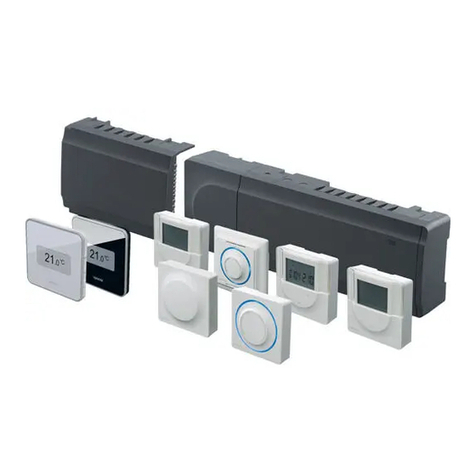
Uponor Climate Control-Multifunction User manual

Uponor Climate Co
˘ntrolTM -
Multifunction Installation Guide
RADIANT HEATING SYSTEMS
CLIMATE CO
˘NTROL™ -
MULTIFUNCTION
INSTALLATION GUIDE

www.uponor-usa.com • www.uponor.ca
Uponor Climate Co˘ntrol™ - Multifunction Installation Guide
i
Uponor Climate Co˘ntrol™ - Multifunction Installation Guide
Published by Uponor, Inc.
5925 148th Street West
Apple Valley, MN 55124 USA
Phone: (800) 321-4739
Fax: (952) 891-1409
www.uponor-usa.com
© 2008 Uponor, Inc.
All Rights Reserved.
First Edition
First Printing January 2008
Printed in the United States of America
Table of Contents
Section 1 — Climate Co˘ntrol™ - Multifunction System 1
System Overview.......................................... 1
Section 2 — System Functionality .................3
Boiler Operation .......................................... 3
Boiler Protection (optional setting) ........................... 3
Domestic Hot Water (DHW) ................................. 3
Zone Pump Control........................................ 3
Mixing.................................................. 3
Snow Melting ............................................ 3
Semi-automatic Control .................................... 4
Fully Automatic Control .................................... 4
Slab Idle ................................................ 4
High Temperature ......................................... 4
Pump Exercising .......................................... 4
Section 3 — Safety Measures . . . . . . . . . . . . . . . . . . . . 5
Section 4 — Climate Co˘ntrol - Multifunction
Installation ..................................7
Mounting the Control Panel ................................. 8
Connecting Mechanical Devices to the Controller................. 9
Wiring Connections for the Climate Co˘ntrol
- Multifunction Control Board .............................. 11
Boiler Connections ....................................... 12
Multiple Boiler Stages ..................................... 13
Modulating Condensing Boilers ............................. 14
Modulating Valves and Mixing .............................. 15
Pump Connections ....................................... 16
Snow-melt Connections ................................... 20
Wiring and Connection Template ............................ 22
Setup and Commissioning.................................. 23
The Display Unit ......................................... 23
Setting the Date and Time ................................. 24
Setting the Temperature Units .............................. 24
Setting the Display's Backlighting............................ 25
Checking the Software Version .............................. 25

www.uponor-usa.com • www.uponor.ca
ii
Uponor Climate Co˘ntrol™ - Multifunction Installation Guide 1
Section 1
The Climate Co
˘ntrolTM -
Multifunction System
System Overview
Uponor introduces Climate Co˘ntrol™ - Multifunction, the industry’s rst
control systems platform that supports all functions required in today’s
heating control systems.
With user-friendly wiring and setup, which allows for optimal installation
through an easy-to-use display, Climate Co˘ntrol - Multifunction's standard
functionality and operation include:
• Boiler staging and rotation
• Domestic hot water (DHW) operation
• Water-temperature mixing
• Automatic or slab-sensing snow melting
• Optional zone pumping
Climate Co˘ntrol - Multifunction's architecture supports up to eight
outputs (e.g., pumps, modulating valves, boilers). The unused ports can
support additional zone pumps within the system rather than adding
other control elements.
Viewing Boiler and Primary Pump Information .................. 25
Viewing Mix Channel Information ............................ 26
Viewing Snow-melt Information ............................. 27
Viewing Domestic Hot Water (DHW) Information................ 28
Section 5 — Setting-up Functionality .............29
Setting-up Boiler Functionality .............................. 29
Setting-up Domestic Hot Water (DHW) Functionality ............ 30
Setting-up Primary Pump Functionality ....................... 31
Setting-up Mixing Functionality ............................. 31
Heating Function........................................32
SM (Snow-melt) Function .................................33
Setting-up Secondary Pump Functionality ..................... 33
Heating Function........................................33
SM (Snow-melt) Function .................................34
Setting-up Zone Pump Functionality ......................... 34
Heating Function........................................34
SM (Snow-melt) Function .................................34
Setting-up Snow Melt Sensor Functionality .................... 35
Clearing Port Functions.................................... 36
Clearing all Settings ...................................... 36
Troubleshooting ......................................... 37

www.uponor-usa.com • www.uponor.ca
2
Uponor Climate Co˘ntrol™ - Multifunction Installation Guide 3
Section 2
System Functionality
The Climate Co˘ntrol - Multifunction hydronic controller is built to handle
various mechanical functions and operates based on how the user sets up
the software through the display module.
The following describes Climate Co˘ntrol's functionality:
Boiler Operation
The boiler res until it reaches a maximum temperature during
commissioning. The temperature of the primary loop drops until the
temperature approaches the boiler's target temperature, which is determined
by what part of the system is calling for heat.
Boiler Protection (optional setting)
Climate Co˘ntrol - Multifunction unit monitors the return boiler temperature.
If the temperature drops too low, the system will begin to close the three-
way valves. If this option doesn't work, the high-temperature pumps will
shut down.
Domestic Hot Water (DHW)
Domestic Hot Water (DHW) function is controlled and operated through
either a sensor or aquastat (switched) input for a single-tank installation.
Zone Pump Control
The system integrates zone pump operation, which controls unused ports
within the Climate Co˘ntrol - Multifunction unit.
Mixing
Up to three independent water temperatures for either space heating or
snow melting can be mixed, accomplished through either a valve or injection
pump. (Uponor recommends using a valve.)
Snow Melting
Climate Co˘ntrol - Multifunction system provides heat to melt snow and ice.
If boiler protection is needed, the system will reduce the heat output of the
snow-melt system.

www.uponor-usa.com • www.uponor.ca
4
Uponor Climate Co˘ntrol™ - Multifunction Installation Guide 5
Semi-automatic Control
Heat is supplied to the snow-melt slab for periods of time specied by
the user:
• Slab Delta T — Used when ramping up the snow-melt slab
temperature. The system limits the water temperature to the slab to
prevent the Delta T from exceeding a maximum temperature.
• Slab setpoint — The system will cease to apply heat once the slab
setpoint is reached.
• High outdoor temperature limit — Snow melting is disabled when
the outdoor temperature exceeds a determined value.
• Low outdoor temperature limit — Snow melting is disabled when
the outdoor temperature drops below a determined value.
• Maximum water temperature — This is the maximum water
temperature the system supplies to the slab.
Fully Automatic Control
When the snow and ice sensor detects snow and ice, the system applies heat
in the same manner it does under semi-automatic control. The difference is
that the system will not stop until the snow and ice detector is clear of ice
and snow and the run timer expires.
Slab Idle
The slab idle setting allows the slab to maintain a set temperature.
High Temperature
If the control supports high-temperature control, the system will turn on
the high-temperature pump until the demand call ends. However, if the
minimum boiler-return temperature is approached, the high-temperature
pump may be turned off to reduce the load on the boiler.
Pump Exercising
After seven days of not operating, a pump or three-way valve will
automatically turn on for two minutes and then automatically turn off.
Section 3
Safety Measures
Important: Failure to follow the instructions and installation
steps in this guide can result in the failure of the Climate Co˘ntrol
- Multifunction system.
• Read the instructions. Do not make changes or modications specied
in this guide. Uponor is not responsible for damages and breakdowns
that may result from not adhering to these instructions.
• Installation must be performed by a qualied installer according to
local codes and regulations.
• Always turn off power when performing any wiring functions
or connections.
• The Climate Co˘ntrol - Multifunction system uses a 24VAC/50VAC/60Hz
power supply. In case of an emergency, immediately disconnect the
power from the controller.
• Keep sensor cables away from power lines greater than 50VAC to avoid
interference.
• Do not use water to clean the controller. Do not expose the controller to
ammable vapors or gases.

www.uponor-usa.com • www.uponor.ca
6
Uponor Climate Co˘ntrol™ - Multifunction Installation Guide 7
Section 4
Climate Co
˘ntrol -
Multifunction Installation
Before installing the Climate Co˘ntrol - Multifunction unit, verify the package
contents with the following list:
• Installation guide
• Main control panel
• Outdoor sensor
• Supply and return sensor (or dual sensor)
• Data key (mounted inside display enclosure)
Important: Read the following installation instructions prior
to installing the display and main control. It will prevent any
unnecessary rework.
Backplate for Display Unit
Cover for Inputs
Display Unit
Front Cover Display Unit
Cover for Outputs (RJ45)
Main Controller
Backplate for Main Control

www.uponor-usa.com • www.uponor.ca
8
Uponor Climate Co˘ntrol™ - Multifunction Installation Guide 9
The display and main control are packaged as a single unit, assembled and
pre-wired for operation. Uponor recommends mounting the main control
panel in the mechanical room or near the mechanical equipment it will
operate to eliminate any unnecessary wiring.
These tools and hardware are necessary for installation:
• Screws and/or anchor hardware for mounting
• Flathead and Phillips screwdrivers
• Wire cutters/strippers
• Level
• Thermostat wire, 18/2 AWG for connecting sensors
• Cat5 wire for connecting pumps, valves or boiler
• Cat5 cable stripper (optional, but recommended if making custom cables)
• Cat5 cable tester
Mounting the Control Panel
1. Select a smooth, at, uniform surface.
2. Select the proper screws and/or anchors for the
surface. Four screws or anchors will properly
secure the unit.
3. Remove the side wings of the main control by
loosening the four screws on the control unit.
This will expose holes necessary to mount to
the selected surface.
4. Install the rst screw semi-tightly so the control
can be rotated. (See Figure 4-1.)
5. Level the control prior to installing any
additional screws. Mark the location with
a pencil or pen if anchors are being used.
(See Figure 4-2.)
6. Install the remaining screws to nish mounting
the control.
Optional Control Panel Mounting
7. Remove the display cover if it is necessary to
secure the panel. (See Figure 4-3.)
8. Apply downward pressure and pull the bottom
of the display away from the backing by placing
a thumb on the bottom of the display and
ngers on the display's top.
9. Use the access holes in the back of the
panel to secure to the wall or surface.
(See Figure 4-4.)
10. Replace the front enclosure.
Connecting Mechanical
Devices to the Controller
The layout of the wiring connections makes for
a quick and simple installation. All connections
on the control's right side are made to boilers,
pumps, modulating valves and snow melt using
RJ45 connectors and a Cat5 cable. Once the
cable is available and tested, it plugs into the
connector on the control's right side and
clicks into place to secure the connection.
(See Figure 4-5.) The connection can easily
be changed or moved by pressing down on the
latch and disconnecting from the control.
The top two ports on the control's right side are
reserved for boilers. If a second boiler is not part
of the mechanical system, the second port can
be used for any other device.
Figure 4-1
Figure 4-4
Figure 4-5
Figure 4-2
Figure 4-3

www.uponor-usa.com • www.uponor.ca
10
Uponor Climate Co˘ntrol™ - Multifunction Installation Guide 11
The control's left side has inputs using push-style connectors, so the use of
a small tip screwdriver is not required. (See Figure 4-6.)
These connectors require dry-contact inputs from
switching relays, thermostats or any other similar
devices. The bottom four connectors are fully
programmable outputs.
When active, LEDs for the inputs and outputs
will turn green.
On Tx
RunRx
Port 1
Input 1
OperateMMI
Port 8
Input 8
Port 3
Port 2
Port 4
Port 5
Input 2
Input 3
Input 4
Input 5
Port 6
Input 6
Port 7
Input 7
Rx
Tx
Intercon
Expansion Connector
(future)
24 VAC IN
Input 1
Input 2
Input 3
Input 4
Input 8
Input 5
Input 7
Input 6
Programmable Output 1
Display Unit
Connector
Port 1
Programmable Output 2
Programmable Output 3
Programmable Output 4
Outdoor Sensor
Port 2
Port 3
Port 4
Port 5
Port 6
Port 7
Port 8
Wiring Connections for the Climate Co˘ntrol -
Multifunction Control Board
Figure 4-6
Figure 4-6

www.uponor-usa.com • www.uponor.ca
12
Uponor Climate Co˘ntrol™ - Multifunction Installation Guide 13
Boiler Connections
When connecting to boilers or any type of heating devices that require
an input or signal to start, an Uponor Boiler Control (A9012010) is required.
This boiler control provides two dry contact outputs and B terminals.
Terminal A is typically wired to start a heating device and is connected to
the Climate Co˘ntrol - Multifunction controller using the proper-length Cat5
wire with RJ45 connectors. (See Figure 4-7.)
The boiler relay comes with a set of LEDs to show the status of the device.
The A and B lights will turn red when the Multifunction Climate Co˘ntrol
unit turns either of the relays on for heat. The green LED will illuminate
when the relay box is connected correctly to the Climate Co˘ntrol -
Multifunction unit. A manual override switch for each set of terminals
(A and B) is located inside the cover. These will operate when the relay is
not connected to the control via a Cat5 cable.
Figure 4-7: Typical wiring of a heating device using an Uponor Boiler Control (A9012010)
for space heating
Auto
Man
A Terminal B Terminal
AB
Power
Space
Heating
High Te mp
DHW
Typical heating device (e.g., boiler)
To p View
Side View
On Tx
RunRx
Port 1
Input 1
OperateMMI
Port 8
Input 8
Port 3
Port 2
Port 4
Port 5
Input 2
Input 3
Input 4
Input 5
Port 6
Input 6
Port 7
Input 7
Rx
Tx
Intercon
Boiler Control (A9012010)
To Climate Co˘ntrol Main Panel
Multiple Boiler Stages
The Climate Co˘ntrol - Multifunction controller can run multiple boiler stages
(up to four) to optimize and regulate the proper amount of heat based
on outdoor temperature and loads. (See Figure 4-8.) As the temperature
differential increases between the supply and return sensors, the Climate
Co˘ntrol - Multifunction system will turn on an additional boiler. As the
differential decreases, the controller will turn off and rotate usage of the
boilers to ensure that the run time on each is equal.
Figure 4-8: Typical wiring of four boiler stages
Man
A Terminal
Auto
B Terminal
A Terminal
Man
B Terminal
Auto
Heating Device 2
Heating
Space
Top View
Heating Device 4
Space
Heating
Top View
On Tx
RunRx
Port 1
Input 1
OperateMMI
Port 8
Input 8
Port 3
Port 2
Port 4
Port 5
Input 2
Input 3
Input 4
Input 5
Port 6
Input 6
Port 7
Input 7
Rx
Tx
Intercon
Boiler Control (A9012010)
Heating Device 1
Heating
Space
Heating Device 3
Space
Heating
To Climate Co˘ntrol Main Panel

www.uponor-usa.com • www.uponor.ca
14
Uponor Climate Co˘ntrol™ - Multifunction Installation Guide 15
Modulating Condensing Boilers
When there is a call for heat, the A terminal on boiler controls calls on
modulating (modcons) boilers. The Climate Co˘ntrol - Multifunction unit
cannot override the boiler settings through the A terminals. However, most
modcons allow a second input for domestic hot water (DHW) or other
high-temperature requirements. In these types of installations, the
B terminals on the boiler control provide that function. (See Figure 4-9.)
Note: Consult the boiler manufacturer’s installation and wiring instructions
to verify the high-temperature override.
Figure 4-9: Typical wiring of a heating device using boiler control for space heating
Auto
Man
A Terminal B Terminal
ABPower
Space High Temp
HeatingDHW
Typical heating device (e.g., boiler)
Top View
Side View
On Tx
RunRx
Port 1
Input 1
OperateMMI
Port 8
Input 8
Port 3
Port 2
Port 4
Port 5
Input 2
Input 3
Input 4
Input 5
Port 6
Input 6
Port 7
Input 7
Rx
Tx
Intercon
Boiler Control (A9012010)
To Climate Co˘ntrol Main Panel
Modulating Valves and Mixing
The Climate Co˘ntrol - Multifunction controller provides mixing and water
temperature control in secondary piping for lower temperature applications,
such as radiant oor heating and snow melting. The Climate Co˘ntrol hydronic
controller can connect to any 0-10VAC motor and valve using the Uponor
Modulating Valve Control (A9063020).
Note: The motor must be 75 milliamps or less from a 24VAC supply or it
must be externally powered.
The Climate Co˘ntrol - Multifunction unit supports up to three separate water
temperatures, any combination of three for space heating and up to two
maximum for snow melting. Supply-and-return Dual Sensors (A9013001) are
plugged into the valve box using a Cat5 cable. (See Figure 4-10.) The ports
are not dedicated so any connection port can be used for connecting sensors
and cable to the Climate Co˘ntrol - Multifunction unit. These 10K sensors are
strapped or mounted to the secondary piping for temperature data to set the
proper position of the valve, based on outdoor temperature, load
requirements, etc.
Note: Uponor stocks pre-assembled 3
/4" - 11
/2" valves.
Auto
Man
PowerActive
To p View
Side View
On Tx
RunRx
Port 1
Input 1
OperateMMI
Port 8
Input 8
Port 3
Port 2
Port 4
Port 5
Input 2
Input 3
Input 4
Input 5
Port 6
Input 6
Port 7
Input 7
Rx
Tx
Intercon
Return Sensor
Supply Sensor
GRN
(FB)
(Cntrl)
WHT (Com)
BLK
(PWR)
RED
Uponor Modulating
Valve Control (A9063020)
Supply-and-return
Dual Sensors (A9013001)
To Climate Co˘ntrol
Main Panel
Figure 4-10: Typical wiring of a modulating valve in a mixing application using Uponor
Modulating Valve Control (A9063020)

www.uponor-usa.com • www.uponor.ca
16
Uponor Climate Co˘ntrol™ - Multifunction Installation Guide 17
The valve relay comes with a set of LEDs to show the relay's status.
Terminal strips for wiring connections to the valve motor and a manual
switch are contained inside the cover. The manual switch, when set to the
Man position, overrides any control signal coming from the Climate Co˘ntrol -
Multifunction controller and allows the installer to set the valve position.
Caution: Failure to return the manual switch to the auto position
will affect the correct regulation of secondary water temperatures.
When the valve box is connected properly to the control, the
power light turns green. The active light turns red whenever the
control is changing the position of the valve for mixing.
The Climate Co˘ntrol - Multifunction unit supports variable speed injection
mixing, which requires an Uponor Pump Relay Box (A9013030). (See Pump
Connections below for additional information on wiring.) Uponor promotes
the use of modulating valves rather than injection pump valves due to lower
power consumption and staying in line with the industry as it moves toward
modulating and condensing boilers.
Pump Connections
Climate Co˘ntrol - Multifunction unit supports on/off operation of pumps
(maximum of three amps) in a variety of applications. Common types of uses
include primary, secondary and domestic hot water (DHW) pumps. As an
added feature, the Climate Co˘ntrol - Multifunction hydronic controller can
be congured to run zone pumps on open or spare ports.
All pumps are quickly and easily connected using Cat5 cables. The Pump
Relay Box comes with LEDs to show the status of the relay. When the relay
and the pump are wired correctly, the auto light will turn green when power
is applied to the circuit. When the system turns on the pump, the Call and
On lights will turn green. A manual switch is included under the top cover
of the relay. When this switch is set to the manual position, the On light will
turn green, provided the auto light is on. When set to the manual position,
the manual switch overrides any control signal coming from the Climate
Co˘ntrol - Multifunction controller and allows the pump to run continuously.
(See Figure 4-11.)
Caution: Failure to return the manual switch to the auto position
can lead to overheating.
Supply-and-return
Dual Sensors (A9013001)
Pump Relay
Box (A9013030)
Supply Sensor
Return Sensor
To p View
Auto
Manual
White
Red
Black
Auto On
Call
Side View
To Climate Co˘ntrol
Main Panel
On Tx
RunRx
Port 1
Input 1
OperateMMI
Port 8
Input 8
Port 3
Port 2
Port 4
Port 5
Input 2
Input 3
Input 4
Input 5
Port 6
Input 6
Port 7
Input 7
Rx
Tx
Intercon
Figure 4-11: Typical wiring of a pump or circulator using Pump Relay Box (A9013030)

www.uponor-usa.com • www.uponor.ca
18
Uponor Climate Co˘ntrol™ - Multifunction Installation Guide 19
The Pump Relay Box
comes with a ¾-inch
thread for mounting to
circulators. Some
manufacturers produce
pumps that allow for
two electrical
connections on the
motor housing. (See
Figure 4-13.) When
this option is available,
the Pump Relay Box
will thread directly into
this tapping for easy
mounting. When this
option is not available,
use standard electrical
boxes with pump relays.
Figure 4-13. Single- and double-gang electrical box with switch
Off
Call OnAuto
Line Voltage In
( 115v )
L
N
Black
Red
White
or Circulator
Wire to Pump
( 2 amps Max )
On
( 2 amps Max )
or Circulator
Wire to Pump
L
N
Black
Call Auto
Line Voltage In
( 115v )
Black
Red
White White
Red
Wire to Pump
or Circulator
( 2 amps Max )
OnAutoCall
Pump Relay
(A9013030)
Pump Relay
(A9013030)
Pump Relay
(A9013030)
The Climate Co˘ntrol - Multifunction system offers additional exibility and
can be daisy-chained — where two pumps turn on simultaneously (e.g., in a
heat exchanger application when the primary pump needs to turn on at the
same time as the secondary pump). The two connectors that come with each
Pump Relay Box are universal (i.e., the ports are not dedicated).
(See Figure 4-12.)
Figure 4-12. Typical connection of multiple pumps using one control signal
Auto
Manual
Top View
On Tx
RunRx
Port 1
Input 1
OperateMMI
Port 8
Input 8
Port 3
Port 2
Port 4
Port 5
Input 2
Input 3
Input 4
Input 5
Port 6
Input 6
Port 7
Input 7
Rx
Tx
Intercon
Return Sensor
Supply Sensor
Top View
Manual
Auto
Supply-and-return
Dual Sensors (A9013001)
To Climate Co˘ntrol
Main Panel
Pump Relay
Box (A9013030)
Pump Relay
Box (A9013030)

www.uponor-usa.com • www.uponor.ca
20
Uponor Climate Co˘ntrol™ - Multifunction Installation Guide 21
Snow-melt Connections
Climate Co˘ntrolTM - Multifunction supports snow-melt operation through
the Uponor Snow Melt Control (A9013051). The Snow Melt Control, which
wires to the main control panel using a Cat5 cable and RJ45 ends for simple
and easy connections, can plug into any port other than what is reserved
for boiler connection. This basic snow-melt package allows for slab sensing
to control the slab temperature for melting. (See Figure 4-14.) An active
red LED is included on the snow-melt control to indicate when the area is
heating. A manual button is also included to start a melting cycle if the idle
feature is not used. Terminals are optional when a remote-mounted switch or
button is required outside of the mechanical room or area.
Figure 4-14: Typical snow-melt connection with slab sensing
Auto
Active
Remote Push
Button (optional)
Top View
Side View
On Tx
RunRx
Port 1
Input 1
OperateMMI
Port 8
Input 8
Port 3
Port 2
Port 4
Port 5
Input 2
Input 3
Input 4
Input 5
Port 6
Input 6
Port 7
Input 7
Rx
Tx
Intercon
Uponor Snow
Melt Control
(A9013051)
10K Slab Sensor
To Climate Co˘ntrol
Main Panel
The Climate Co˘ntrol - Multifunction System supports automatic snow-melt
operation when using Uponor Automatic Snow and Ice Sensor (A9013052).
This package includes a sensor and a socket to detect snow or ice and
automatically enables the system to start a melting cycle. (See Figure 4-15.)
Note: Other manufacturer snow and ice sensors are not compatible.
Figure 4-15: Typical snow-melt connection with slab sensing and snow and ice detector
Auto
Active
Remote Push
Button (optional)
To p View
Side View
On Tx
RunRx
Port 1
Input 1
OperateMMI
Port 8
Input 8
Port 3
Port 2
Port 4
Port 5
Input 2
Input 3
Input 4
Input 5
Port 6
Input 6
Port 7
Input 7
Rx
Tx
Intercon
Uponor Snow
Melt Control
(A9013051)
10K Slab Sensor
Dedicated Transformer
24VAC Requirement
(Supplied by others)
Red
Black
and Ice Sensor
Automatic Snow
To Climate Co˘ntrol
Main Panel

www.uponor-usa.com • www.uponor.ca
22
Uponor Climate Co˘ntrol™ - Multifunction Installation Guide 23
Wiring and Connection Template
Use the following template to record the connections and devices in the
system before display setup. For the Output Ports section, place an X inside
the appropriate box, indicating the port number and the function it connects.
For the Input Ports section, describe what is connected to each port
(e.g., thermostat, zone control module, relay, etc.). Check the box at the end
of the descriptions to indicate if that connection is wired. Use the section
provided for Programmed Output Ports in the same manner.
Note: When wiring, use the Demand Input Label as a guide. Inputs and
ports may not line up with the Demand Input Label.
Wiring and Connection Schedule
Setup and Commissioning
Prior to beginning any setup or commissioning function, check the following:
• The wiring is complete.
• The wiring and device connections are recorded properly on the
sheet provided.
• The wiring compartments are enclosed.
• The display is lit and showing the Uponor logo, default date and time
and outdoor temperature.
Initial Setup
The Display Unit
The display unit included in this package is an easy-to-use device,
comprised of LCD display and ve-button interface (i.e., up, down, left,
right and OK).
OK
Interface Keys
Right
Arrow Displays the
next menu or Goes to the next
eld
Left
Arrow Displays the
previous menu or
Goes to the
previous eld
Pressing longer
in a menu screen
will display the
Uponor screen
Up
Arrow Goes to the
line above or Increases the
value
Down
Arrow Goes to the
line below or Decreases the
value
Center
Button OK Displays the
next screen or
Conrms
selection and/
or displays the
screen of the
current menu
Output
Ports Boiler
Primary
Pump DHW Mix
Secondary
Pump
Snow-
melt
Sensor
SM
WTC*
Zone
Pump
Demand
Input
Demand
Output
Port 1
Port 2
Port 3
Port 4
Port 5
Port 6
Port 7
Port 8
Input Ports Description
Port 1
Port 2
Port 3
Port 4
Port 5
Port 6
Port 7
Port 8
Outdoor Sensor
Programmed
Output Ports Description
Port 1
Port 2
Port 3
Port 4
*Water Temperature Control

www.uponor-usa.com • www.uponor.ca
24
Uponor Climate Co˘ntrol™ - Multifunction Installation Guide 25
Setting the Date and Time
The date and time screen will automatically appear when the controller
is turned on for the rst time. Access this menu at: Uponor Screen > Settings
> System Settings > Clock >. (The use of the > symbol indicates pressing the
OK button.)
The following settings are available:
• Date and Time — Change year, month
and time of day.
• AM/PM — Change to 24-hour time or
AM/PM time display.
• Date Format — Change how the month,
day and year will appear on the display.
• Daylight Savings — Set the date (Fixed Date)
or Cancel Daylight Saving.
• Press or for the right setting, then
press OK.
• Adjust as necessary, then press OK to return to
the clock menu.
Setting the Temperature Units
Set the Climate Co˘ntrol - Multifunction controller
to display temperature units as either Fahrenheit
(°F) or Celsius (°C). To change the units, follow
this path: Uponor Screen > Settings > System
Settings > Units >. (The use of the > symbol
indicates pressing the OK button.)
The following setting is available:
• Select °F or °C (default is °F), then press OK.
Setting the Display's Backlighting
To adjust the display's backlighting to change the backlight settings, follow
this path: Uponor Screen > Settings > System Settings > Backlight >.
(The use of the > symbol indicates pressing the OK button.)
The following settings are available:
• Backlighting On — Display remains at
100% intensity at all times.
• Backlighting Dimmed — Display will go
to 50% intensity after 10 seconds of last
button pressed.
• Backlighting Off — Display will go dark
after 10 seconds of last button pressed.
Note: Display will return to 100% intensity upon next button press
when backlighting is set to Dimmed or Off.
• Press or for the right setting, then press OK.
View Menus
Checking the Software Version
Designed to be upgradated in the eld, the
Climate Co˘ntrol - Multifunction software versions
of the interface, database and rmware may
need to be veried as well. To view the software
versions, follow this path: Uponor Screen >
Information > Software Versions >. (The use of the
> symbol indicates pressing the OK button.)
Viewing Boiler and Primary Pump Information
When the Climate Co˘ntrol - Multifunction unit is wired and the setup of the
system is complete, boiler and primary pump
operation can be veried along with viewing
temperatures on the supply and return sensors.
To view this information, follow this path: Uponor
Screen > Information > Functions > Boiler and
Primary Pump >. (The use of the > symbol
indicates pressing the OK button.)
The following settings are available:
• Boiler Activity — Display all boiler stages and their current status
(on or off).

www.uponor-usa.com • www.uponor.ca
26
Uponor Climate Co˘ntrol™ - Multifunction Installation Guide 27
• Primary Pump Activity — Display the current status of the pump
(on or off).
• Supply Return Temp — Display current temperature for the supply
and return sensors.
• Press or for the right setting, then press OK.
• Press OK to return to the previous menu for another selection.
Viewing Mix Channel Information
After the Climate Co˘ntrol - Multifunction controller is wired and the setup
complete, verify Mix Channel operation by viewing temperatures on the
supply and return sensors. To view this information, follow this path: Uponor
Screen > Information > Functions > Mix Channel >. (The use of the > symbol
indicates pressing the OK button.)
The following selections are available:
• Port Number — Displays all ports that are
assigned for both the mixing device and
secondary pumps. All devices will
be shown (paired) if more than one mix
channel is setup.
• Mix Channel Activity — Show the current
status of the channel (active or inactive).
• Mix Target — Display the target temperature for the mixed loop if the
channel is active. If not active, 0.0°F displays.
• Mix Average — Display the average temperature for the mixed loop
across the supply and return sensors if the channel is active. If not
active, 0.0°F displays.
• Supply and Return Temp — Display current temperature for the
supply and return sensors if the sensors are connected. If not
connected, 0.0°F displays.
• Press or for the right setting, then press OK.
• Press OK to return to the previous menu for another selection.
Viewing Snow-melt Information
After the Climate Co˘ntrol - Multifunction unit is wired and the setup of the
system is complete, verify snow-melting operation along with viewing
temperatures on the supply and return sensors. To view this information,
follow this path: Uponor Screen > Information > Functions > Snow Melt >
[Channel Choice — only available if two zones of snow melt are set up.]
(The use of the > symbol indicates pressing the
ok button.)
The following selections are available:
• SM Port — Display which port the Snow
Melt Control is assigned to during the
setup process.
• Snow Melt Call — Display the current
status of snow-melt operation.
• Sensor Call — Display indicates if the slab
sensor is requiring heat.
• Semi-Auto Call — Display indicates if a
snow-melting cycle is turned on manually.
• Idle Call — Display indicates if the
snow-melt slab is heating to maintain a
minimum temperature.
• SM Supply Return — Screen displays
current temperature for the Supply and
Return Sensors if they are connected. If
not connected, 0.0°F displays.
• Press or for the right setting, then
press OK.
• Press OK to return to the previous menu
for another selection.

www.uponor-usa.com • www.uponor.ca
28
Uponor Climate Co˘ntrol™ - Multifunction Installation Guide 29
Viewing Domestic Hot Water (DHW) Information
After the Climate Co˘ntrol - Multifunction unit is wired and the setup is
complete, verify DHW operation along with viewing temperature sensor
installed within the tank well or aquastat operation. To view this information,
follow this path: Uponor Screen > Information > Functions > DHW >.
(The use of the > symbol indicates pressing the OK button.)
The following selections are available:
• DHW Port — Screen displays which port
the DHW function is assigned to during the
setup process.
• DHW Call — Screen displays the current status
of DHW operation.
• DHW Temp — Screen displays current
temperature for the tank sensor if connected.
If not connected, 0.0°F displays.
• DHW Setting — Screen displays the
temperature to be maintained.
• Press or for the right setting, then
press OK.
• Press OK to return to the previous menu for
another selection.
Section 5
Setting-up Functionality
This section helps the user understand this
control's full power and exibility.
Application-specic controls inform the user
which devices to connect. Uponor has reversed
this. Climate Co˘ntrol - Multifunction, the most
versatile control in mechanical-room functionality,
allows the installer to tell the control which
devices are connected and which functions to use.
If a port has already been set up for a function,
the menu displays that function in addition to
Clear Port Function. At this point, clear the port
for a new function or press the left to go back
and select an unassigned port. The user can press
clear at any time to begin the selection
process again.
Setting-up Boiler Functionality
The Climate Co˘ntrol - Multifunction unit comes with pre-loaded software
to run and operate up to four boiler stages. As noted earlier in this guide,
Ports 1 and 2 are always dedicated for boiler connections. If only one or two
boilers are being controlled, only Port 1 is used and Port 2 is available for
other functions. If two boilers require the Climate Co˘ntrol - Multifunction
hydronic controller to have one boiler with a DHW override, then both Ports
1 and 2 are required for that operation. See Multiple Boiler Stages on
page 13.
Note: If a heating plant is self-contained — where it controls itself
without any external demand — ports are not assigned or reserved
for boiler operation.
To access the port assignment menu, follow this
path: Uponor Screen > Settings > Ports > Port 1
> Boiler Properties >. (The use of the > symbol
indicates pressing the OK button.)

www.uponor-usa.com • www.uponor.ca
30
Uponor Climate Co˘ntrol™ - Multifunction Installation Guide 31
The following selections are available:
• Number of Boilers — Set the number of
boilers that the control manages.
• No Boiler Limits — Set the requirement
if minimum and maximum temperatures if
needed. If boiler can handle cold-return
temperatures (e.g., condensing boilers),
set to On.
• Enable High Fire — If connecting to a boiler
or heating device that can accept an external
input (dry contact) to override the boiler's
reset curve to start a high re (or DHW call),
set to On.
• Boiler Max Min — Set the limits for both
minimum return and maximum supply
temperatures as read by the sensors. If boiler
limits are set to On (see previous bulletpoint),
no sensors are required and this selection is not
available in the menu.
• Demand Input — Set the input port number
for a connection that will start the boiler or
heating plant. In most applications, this is
required as a demand call for a mixed water
channel, snow melt, zone pump, etc. will
automatically start and manage the boiler.
• Press or for the right setting, then press OK.
• Using the keys, set the information correctly to match the system; then
press OK to accept the information.
Setting-up Domestic Hot Water (DHW) Functionality
The Climate Co˘ntrol - Multifunction unit comes with pre-loaded software
to run and operate a single DHW tank if incorporated into the system. Set
this function to operate off a sensor installed in the tank well or from a
dry contact output from an aquastat or tank-operating control. Other than
the port reserved for the boiler, DHW can be connected and set up on any
available port. To access the port assignment menu, follow this path: Uponor
Screen > Settings > Ports > Port x (where x is any available port) > DHW >.
(The use of the > symbol indicates pressing the OK button.)
The following selections are available:
• DHW Setting — Set the requirement for the tank temperature through
the tank sensor.
• Demand Input — Set the input number for
a connection that will start the DHW call.
Set this only if using an aquastat or dry
contact to initiate the call.
• Demand Output — Set the left
programmable output connection number for
an operation that links to the operation of
the DHW pump.
Note: If in DHW heating mode and the
boiler or heating device needs a
high- temperature demand or
override, see Setting up Boiler
Functionality on page 29 to
properly set this function.
• Press or for the right setting, then press OK.
• Using the keys, set the information correctly to match
the system, then press OK to accept the information.
Setting-up Primary Pump Functionality
The Climate Co˘ntrol - Multifunction unit comes with pre-loaded software to
run and operate a primary pump if incorporated into the mechanical system.
If set up, the primary pump will always turn on with any call for heating.
The exception is to turn off the primary pump when the system is heating
DHW where the primary pump can be turned off during this call to avoid
high water temperatures going to the system. To access the port assignment
menu, follow this path: Uponor Screen > Settings > Ports > Port x (where x
is any available port) > Primary Pump >. (The use of the > symbol indicates
pressing the OK button.)
The following selection is available:
• Turn Off for DHW — Set the primary
pump operation when heating a domestic
hot water tank.
• Using the keys, set the information
correctly to match the system, then press
OK to accept the information.
Setting-up Mixing Functionality
Climate Co˘ntrol - Multifunction unit comes with
pre-loaded software to run and operate up to
three mixed water temperatures for either heating
or snow-melting functionality. To access the port
assignment menu, follow this path: Uponor Screen > Settings > Ports >
Port x (where x is any available port) > Mix Device >. (The use of the >
symbol indicates pressing the OK button.)

www.uponor-usa.com • www.uponor.ca
32
Uponor Climate Co˘ntrol™ - Multifunction Installation Guide 33
Heating Function
The following selections are available:
• Mix Channel Number — Set the number of
the Mixed Channel. This does not correspond
to the port number it is connected to. This is
for reference only.
• Mix Device — Set the device type that will
control the actual mixing function.
• Design Room Temp — This setting indicates
the typical room temperature is set by the
occupants through the heating season and
used in the design heat-loss calculation.
• Design Water Temp — This setting indicates
the water temperature the control will deliver
at the Design Outdoor temperature.
• Design Outdoor Temp — Set for typically
the coldest outdoor temperature during a
normal heating season.
• WWODT (Warm Weather Outdoor
Temperature) — This setting is used for
all heating functions where heating is no
longer required.
• WWWT (Warm Weather Water
Temperature) — This setting denes the
water temperature that will be delivered at
the WWODT.
• Mix Delta T — Set for the target differential temperature between the
supply and return sensors.
• Input — Set the input port number for a connection that will start the
mix call.
• Output — Set the left programmable output connection number for a
connection that will link to the operation of that mix device.
• Press or for the right setting, then press OK.
• Using the keys, set the information correctly to match the system; then
press OK to accept the information.
SM (Snow-melt) Function
The following selections are available:
• SM Channel — This sets a reference number.
This does not correspond to the port number
it connects to. This must be set to the same
SM Channel when the sensor port is set up.
• Mix Device — Set the device type that
controls the actual mixing function.
• SM Max Water Temp — This setting
indicates the maximum allowable water
temperature delivered to the snow-melt
slab or area.
• SM Output — Set the left programmable
output connection number for a connection
that will link to the operation of that mix device.
• Press or for the right setting, press OK.
• Using the keys, set the information correctly
to match the system; then press OK to accept
the information.
Setting-up Secondary Pump Functionality
The Climate Co˘ntrol - Multifunction unit comes
with pre-loaded software to run and operate
secondary pumps linked to the mixing device if
used. (The Climate Co˘ntrol - Multifunction will
support zone pump functionality.) To access the
port assignment menu, follow this path: Uponor
Screen > Settings > Ports > Port x (where x is any
available port) > Secondary Pump >. (The use of
the > symbol indicates pressing the OK button.)
Heating Function
The following selection is available:
• Mix Channel Number — This sets the
reference number. This does not correspond
to the port number it is connected to. This is
for reference only.
• Press or for the right setting, then
press OK.
• Using the keys, set the information correctly
to match the system; then press OK to accept
the information.

www.uponor-usa.com • www.uponor.ca
34
Uponor Climate Co˘ntrol™ - Multifunction Installation Guide 35
Setting-up Snow Melt Sensor Functionality
The Climate Co˘ntrol - Multifunction unit comes with pre-loaded software to
run and operate up to two zones or areas of snow melting. Depending on
the type of sensor used, the snow melting can be set up for semi-automatic
operation (i.e., slab sensor only) or fully automatic operation (i.e., snow and
ice detector). To access the port assignment menu, follow this path: Uponor
Screen > Settings > Ports > Port x (where x is any available port) > Snow
Melt Sensor >. (The use of the > symbol indicates pressing the OK button.)
The following selections are available:
• SM Channel — This sets a reference
number. This does not correspond to the
port number it connects to. This must be
set to the same SM Channel when the
sensor port is set up. If no mixing is
required for water temperature control,
set this value to zero.
• Idle Enable — This setting indicates
whether the slab or snow-melt area will
maintain a minimum temperature.
• Idle Setpoint — This setting indicates
the minimum temperature the slab or
snow-melt area will maintain.
• Semi-auto Setpoint — This setting
indicates the temperature of the slab or
snow-melt area the slab will maintain when
a snow-melt call is started, either manually
(button press) or automatically from the
snow and ice sensor if used.
• Semi-auto Timeout — This setting indicates
the duration the call for snow-melt will
continue after the slab has reached its setpoint
or the sensor is clear from snow or ice.
• Outdoor Hi Low Temp — This setting
indicates the outdoor temperatures all
snow-melt functions will no longer run.
• SM Delta T — This setting indicates the
target differential temperature between the
supply and return sensors.
SM (Snow-melt) Function
The following selection is available:
• SM Channel — This sets a reference number.
This does not correspond to the port number it
connects to. This must be set to the same
SM Channel when the sensor port is set up.
• Press or for the right setting, then
press OK.
• Using the keys, set the information correctly
to match the system, then press OK to accept
the information.
Setting-up Zone Pump Functionality
The Climate Co˘ntrol - Multifunction unit comes with pre-loaded
software to run and operate zone pumps for either heating or snow-
melting functionality. To access the port assignment menu, follow this path:
Uponor Screen > Settings > Ports > Port x (where x is any available port) >
Mix Device >. (The use of the > symbol indicates pressing the OK button.)
Heating Function
The following selections are available:
• Input — Set the input port number for a
connection that will start the zone pump call.
• Output — Set the left programmable output
connection number for a connection that links
to the operation of that mix device.
• Press or for the right setting, then
press OK.
• Using the keys, set the information correctly
to match the system; then press OK to accept
the information.
SM (Snow-melt) Function
The following selection is available:
• Output — Set the left programmable output
connection number for a connection that links
to the operation of that mix device.
• Press or for the right setting, then
press OK.
• Using the keys, set the information correctly
to match the system; then press OK to accept
the information.
Table of contents
Other Uponor Control System manuals
Popular Control System manuals by other brands

Faudi
Faudi CCS silver operating instructions

FW Murphy
FW Murphy TTD Series Installation and operation manual

Siemens
Siemens SINUMERIK 840D sl Function manual

IntelligentAg
IntelligentAg RECON SPREADSENSE installation manual

JETI model
JETI model DC-14 II user manual

Carel
Carel MasterCella Split user manual