K&K Systems Crosslink User manual


32
Warranty................................................................................................................3
Thank You .............................................................................................................4
Introduction ........................................................................................................5
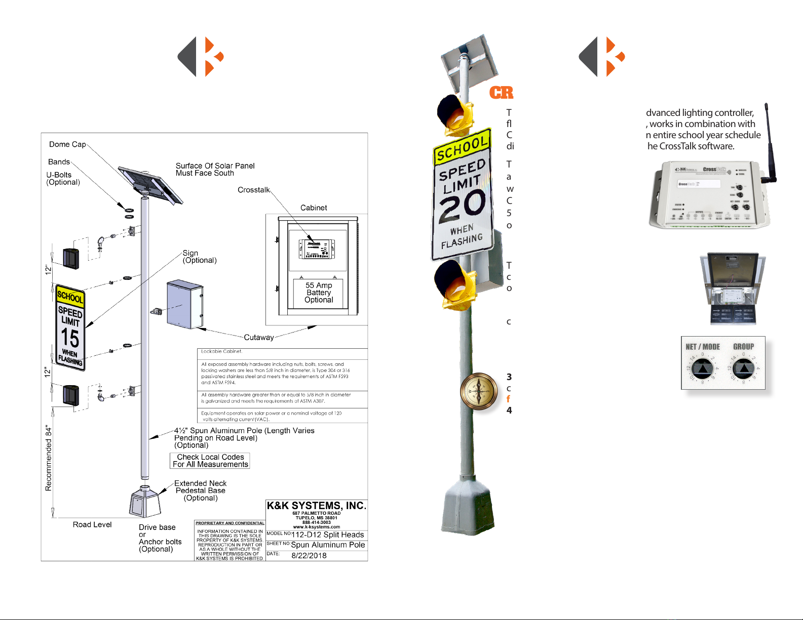
Sign System Assemby / Control Cabinet Components .................6
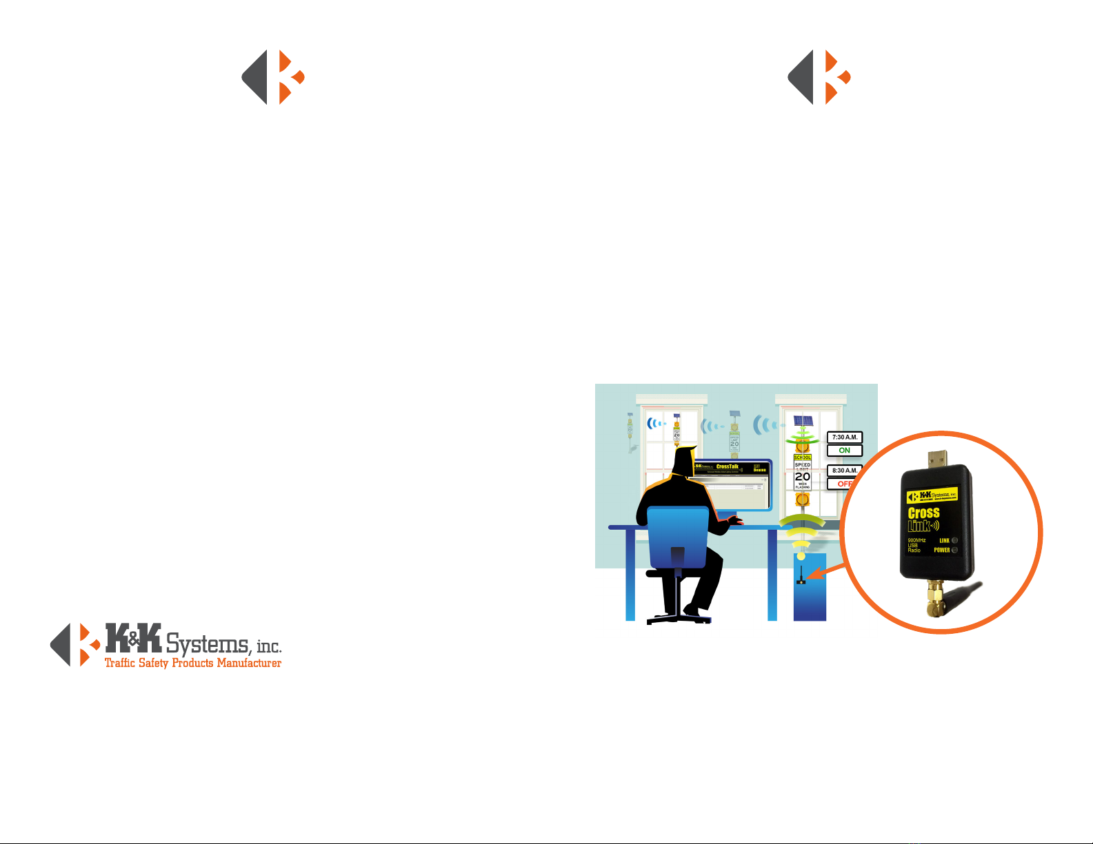
CrossTalk Connection .....................................................................................7
Maintenance.......................................................................................................7
CrossTalk Controls & Networking
Net Address/Grouping ..............................................................8-9
CrossLink/CrossTalk Communication .................................................. 10
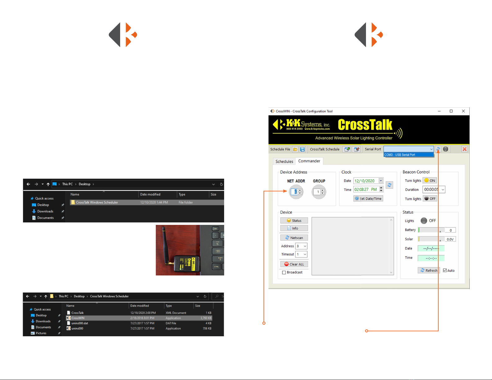
CrossTalk Software ........................................................................................ 11
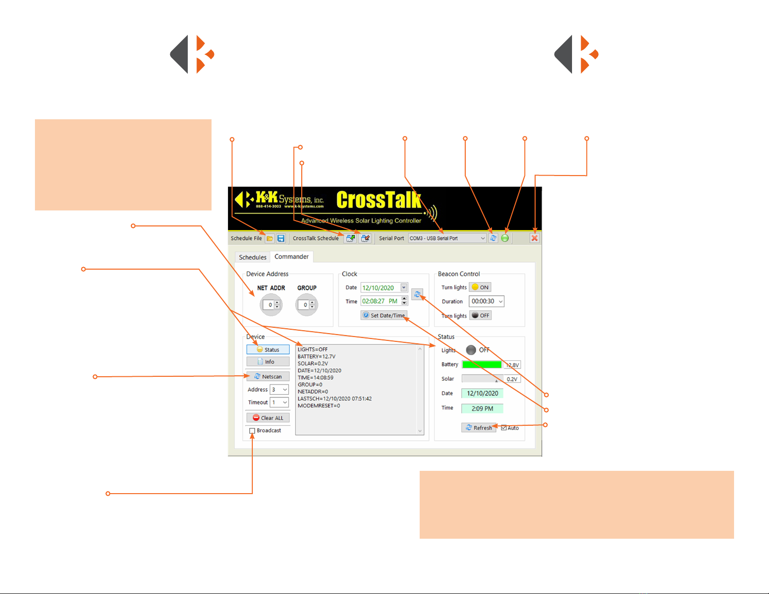
Commander.............................................................................................. 12
Connection Test ...............................................................................12
Device Address................................................................................ 12
Status.................................................................................................... 12
Info......................................................................................................... 12
Network Scan................................................................................... 12
Broadcast................................................................................12
Beacon Control.....................................................................12
Clock.........................................................................................12
Schedules.................................................................................................. 14
Setting a New Standard Schedule......................................... 14
Setting a Holiday Schedule ....................................................... 15
Setting an Exception .................................................................... 15
Delete a Schedule .......................................................................... 15
Troubleshooting.......................................................................................16-17
Fuse Location and Replacement ....................................................18-19
TABLE OF CONTENTS
1. The manufacturer warrants that all products manufactured by K&K Systems, Inc. will be
free from defects in material and workmanship for a period of one (1) year from date of
shipment, subject to the conditions and restrictions contained herein.
2. This warranty does not apply to a product that has not been installed or maintained in
accordance with the manufacturer’s instructions, has been subjected to damage in an
accident, abused or neglected during operation, repaired or modied by persons other
than manufacturer, its employees or authorized agents, or failed to have normal mainte-
nance.
3. The buyer expressly agrees that the buyer’s sole remedy and the manufacturer’s sole re-
sponsibility, in respect to a warranty claim, is exclusively limited to repair or replacement
at the manufacturer’s option, of product or a portion thereof found by the manufacturer
to be defective. The manufacturer is not responsible for labor or other expended charges
by buyer including transportation chargers, an shall not be liable for any incidental or
consequential damages connected with repair of a product deemed to be defective or
with installation or replacement of repaired product. Further, the manufacturer disclaims
any liability for any incidental or consequential damages, including lost or duplicated
time or expense accruing for any reason, to the owner or user or any products sold by
the manufacturer, whether claim is made in contract or in tor or under any theory of
warranty, negligence or otherwise.
4. The manufacturer reserves the right to make changes in its products from time to time,
without incurring any obligation to incorporate such improvements in any products
previously sold or in service.
5. The terms and conditions of the warranty cannot be altered without the written consent
of the manufacturer.
6. The foregoing warranty is exclusive and in lieu of all other express, statutory and implied
warranties INCLUDING THOSE OF MERCHANTABILITY AND FITNESS FOR ANY
PARTICULAR PURPOSE. There are no warranties which extend beyond the language in
the previous six (6) paragraphs.
If you have any further questions, please feel free to call us at our
toll-free number, 888-414-3003, email info@k-ksystems.com or
look us upon the internet at www.k-ksystems.com.
MANUFACTURER’S WARRANTY

54
INTRODUCTION
WHAT IS THE CROSSLINK
The K&K Systems CrossLink is a small USB-connected antenna that uses short
range radio frequency to allows access your school zone sign systems via the
CrossTalk Controller. This system is perfect for areas where internet access is weak or
inaccessible.
The CrossLink, when inserted into your computer and software installed, allows
connection with the Primary CrossTalk. The Primary CrossTalk is located in the
control box on the sign system within approximately 500 feet and within direct line
of sight of the CrossLink. The CrossLink provides access to the CrossTalk software
to set/edit schedules or to retrieve status information for your entire sign system
group.
THANK YOU FOR YOUR BUSINESS!
To Our Valued Customer,
K&K Systems, Inc. is excited that you have purchased our product.
Our company has been serving the trac industry since 1997. Since that
time we have risen to become a leader in the trac industry. We oer a
complete line of trac safety products that include message boards, arrow
boards, radar speed monitors, solar school zone ashers, solar 24-hour
ashers and many other quality products that serve our industry today.
At K&K Systems, Inc., we strive to improve the quality of our products. We
are dedicated to the concept that our customers are our most valuable
resource. We strive to serve our customers as we would want to be served.
Tim Keith,
President

76
SIGN SYSTEM ASSEMBLY/
CONTROL CABINET COMPONENTS The CrossTalk, compact, all-in-one advanced lighting controller,
asher, auto-dimmer and scheduler, works in combination with
CrossLink to control and program an entire school year schedule
directly from your computer using the CrossTalk software.
The CrossTalk Controller’s 900MHz
antenna is used to communicate
with the CrossLink. The Primary
CrossTalk which must be within
500 feet and with a direct line
of sight allows you to control
multiple sign systems at once.
HARDWARE INSTALLATION
The CrossTalk is located inside the aluminum
control box located low on the sign system pole
or under the solar panel for ECO models.
1) Connect the batteries and test the unit
before erecting the pole for convenient working
conditions.
2) Make a note of the CrossTalk Net Address and
Group settings before erecting the system.
You will need the settings for establishing
a connection with the CrossLink device.
3) Check cardinal directions with a
compass to ensure the solar panel is
facing South for proper charging.
4) Insert the CrossLink into your computer’s USB port.
5) See page 10 for software installation and use.
6) Check the sign system a few days after installation to ensure it
is charging and fully operational.
MAINTENANCE
• Periodically inspect sign mounting and antennas to ensure that
they are tight and have not shifted. The solar panel may shift
direction over time. Ensure the panel pointing South.
• Clean the solar panel with glass cleaner to remove the build up
grime that reduces charging eciency.
• Check your battery every 6 months to ensure its health. If below
12V, charge to keep power reserves high, check solar system.
CROSSTALK CONNECTION

8 9
Group Setting
All devices with the
same GROUP setting can
communicate with each
other.
Net/Mode Setting
Unique address setting for
each unit in a group
Status Light
The status light
ashes in sequence with
the rst output to indicate
the asher is active and
ashing rate.
Charging Light
Solar controller status
indicator shows when the
battery is being charged:
Green = Charged
Amber = Charging
Solar Port
Solar connection port LED Outputs
1,2,3,4
Load: 12V LED/DC
asher outputs/
switches (x4).
Maximum load 50W
per output. Output
changes based on
the CrossTalk Mode
Settings.
Battery Light
Battery status light
for safe accurate
connections:
Green = Good
connection
900 MHz Antenna
Wireless Light
When lit, indicates that a
wireless device is connected
Signal Light
Indicates the strength
of wireless signal during
communication
Time
Set the amount of time that
lights ash in hours, minutes,
and seconds
Scale
Multiplies time setting
meaning:
TIME x SCALE= run duration
In 1 / In 2
Digital input range 5-24V DC
for radar, advance warning,
and more
Switch Attachment
Sensor connection port.
Connect any sensor for
use in conjunction with
sign alerts.
Sensor options:
• Push Button
• Moisture Sensor
• Water Level Sensor
• Motion Sensor
• Overspeed Sensor
Ethernet
RS-232
Communication
Port / Laptop
Connection
CROSSTALK CONTROLS &
NETWORKING
A single CrossTalk can control multiple Sign Alert Systems across an entire campus
and connectivity for setting and editing schedules, status monitoring, and
diagnostics with real-time control.
This CrossTalk is NET ADDR 0 in GROUP 0
NET ADDRESS Each CrossTalk unit has a
NET ADDR switch setting that provides each
CrossTalk unit with a unique network address
(0-15) and which can be set easily by hand
with no programming required. This unique
address allows devices (laptops, desktop
computers, etc.) to communicate with a
specic CrossTalk unit. This setting also allows
the user to designate a specic CrossTalk in a
group as the primary link of communication
to other CrossTalk controllers. The primary
CrossTalk is most centralized and easily
accessed unit. The NET ADDR for the primary
CrossTalk unit should be set to “zero” (0).
All other CrossTalk secondary devices in that
same group must have their own unique NET
ADDR without duplication (1-15).
GROUPING CROSSTALK
CONTROLLERS A single CrossTalk
controller can monitor and control up to 15
additional CrossTalk units (for a total of 16
units in a“group”). In addition to the NET
ADDR switch each CrossTalk unit also has a
GROUP switch (0-15) which allows CrossTalk
units to be“grouped”together. All devices
with same Group number can communicate with each other. This grouping
function allows multiple, separate CrossTalk applications to operate in the same
general location (e.g, multiple cross-walks or schools on the same street) yet
provide independent control of each CrossTalk“group”.
In most school lighting applications, for example, there is a designated“primary”
CrossTalk unit and one or more“secondary” CrossTalk units. The secondary units
will receive instructions from and be managed by the primary CrossTalk unit. As
noted above, the NET ADDR for the primary CrossTalk unit should be set to“zero”
(0). All other CrossTalk secondary devices in that same group must have their own
unique NET ADDR without duplication (1-15).
To associate or“group” the primary unit with the
secondary units set the GROUP switch to the same
setting for all units.

1110
CROSSLINK/CROSSTALK
COMMUNICATION
SOFTWARE INSTALLATION
CrossTalk controllers are used for a variety of trac & safety applications including
school zone safety systems, bridge navigation beacons, cross-walk / pedestrian sys-
tems, speed/radar systems and more. Utilizing solar power and both cellular and
short-range wireless connectivity, CrossTalk applications can be setup quickly and
provide more functionality and exibility than traditional“wired”systems. A single
CrossTalk can control multiple nodes across an entire campus and provide web
connectivity for schedules, status monitoring, diagnostics, and real-time control.
Follow the steps below to begin using your CrossLink.
1) Insert the CrossTalk Software Flash Drive that was provided with your sales
documentation into your computer.
2) Drag the CrossTalk Windows Scheduler folder to
your computer’s hard drive.
3) Insert the CrossLink Device into your computer’s
USB port. (Note: It must be plugged directly into your
computer. It does not support access through a hub.)
4)Open the CrossTalk Windows Scheduler folder.
5) Open the CrossWIN software.
CROSSTALK SOFTWARE
To communicate with the CrossTalk(s) to set or edit schedules or to retrieve status
information on your system(s), follow the instructions below. The Schedules and
the Commander tabs provide detailed information about the CrossTalk devices.
By default the Schedules tab opens rst. Select the Commander tab to start the
connection process.
CONNECT TO CROSSTALK CONTROLLERS
1) Check the CrossTalk unit in the beacon system for settings the
NET ADDR and GROUP settings for the desired CrossTalk unit.
2) Input those settings with the same numbers.
3) Click the Serial Port Refresh button.
4) Click the drop down menu y
5) Select the desired unit. Networked Sign Alerts can all be controlled with the Primary CrossTalk.
See the Networking section for more information.

1312
The Commander tab in the CrossTalk main menu provides access to units.
CONNECTION TEST
To ensure the CrossLink is connected to the
Sign Alert CrossTalk, click the ON button
in the Beacon Control area. Check the
sign that the lights are ashing. You may
need to change the Duration for further
conrmation.
DEVICE ADDRESS
Set the NET ADDR and GROUP to match the
primary CrossTalk to connect to it.
STATUS
The status button reports the functioning
condition of the Sign Alert CrossTalk. Click to
inspect Lights/Beacons, Battery Voltage, Solar
Voltage, Date, Time, Group, Net Address, Last
Schedule, and number of times the Modem has
reset itself.
INFO Used by manufacturer
NETSCAN
The NetScan button searches for other local
CrossTalks. The status of each device that
is contacted is displayed. The rst number
following DEV is the Group number set on the
device whereas the second number will be the
Net Address. (i.e.: DEV00, DEV01, DEV02, DEV03).
The Status shown in the Network Scan will list
the Battery Voltage, Solar Voltage, and status of
the lights if on or o.
BROADCAST
Select the Broadcast box to send the signal to all of the units in a GROUP.
COMMANDER
Schedule File
The folder 1
contains saved
schedules. The
disk <saves newly
created schedules.
CrossTalk Schedule
Sends schedules to
the CrossTalk.
Retrieves schedules
from the CrossTalk.
BEACON CONTROL
Turn Lights n
ON
- manually activates lights.
Duration - amount of time the lights will ash.
Primarily used for troubleshooting or special
requirements. Lights automatically turn o after
the designated duration when testing.
Turn Lights n
OFF
- manually deactivates
lights.
CLOCK
The Clock accesses the date and time. The
date and time shown should match that of the
device being used to access the server.
To Set Date and Time:
1) Click the Refresh Button
2) Click the Set Date/Time Button
3) Click the Refresh Button at the bottom of the
Status window.
Serial Port
Selects connected
CrossTalk
Refresh Button
Initiates search for
CrossTalks.
Status Light
Indicates connection.
Green = Connected
Exit Program
GROUP NETWORK
Networking gives the user the ability to communicate with a primary unit and the
surrounding units. By using the (radio) short range (900Mhz), the primary CrossTalk
can access the other units in the Group and send a status messages for the user to
review.

1514
SCHEDULES
The CrossTalk software provides a format to allow a complete year’s schedule to be
programmed. Set Standard and Holiday schedules with up to six exceptions to the
those schedules. To set or edit schedules click the Schedules tab in the app and
follow the steps below.
SETTING A NEW STANDARD SCHEDULE Before
updating all Schedules to the CrossTalk, it is recommended that the
previous schedules on all units in a group be cleared.
1) Select the Start and End dates.
2) Click the Events ++ button
3) Select the time for lights to turn ON in the TURN-ON TIME column.
4) Select the DURATION column to select the length of time the
lights will be on in the.
5) Select the days the schedule applies to by clicking inside the box.
6) Click the WRITE schedule button to send the schedule to the
Sign Alert System.
Schedule File
The folder contains saved schedules.
The disk saves newly created schedules.
CrossTalk Schedule
Retrieves all schedules from CrossTalk.
Sends all schedules to CrossTalk.
SETTING A HOLIDAY SCHEDULE
Setting a Holiday schedule
will prevent the lights from
ashing during those dates.
1) Select the Holiday tab.
2) Click the Events ++ button
3) Click the EVENT column to
change the name if desired
4) Select the Start and End
dates.
5) Click the WRITE schedule
button to send the schedule to
the Sign Alert System.
SETTING AN EXCEPTION
Exceptions allow you to amend
a set standard schedule without
having to create a entire new
schedule.
1) Select an Exception tab.
2) Name the Exception
3) Select the Start and End
dates.
4) Click the Events ++ button
5) Set the TURN-ON TIME
6) Select the DURATION
7) Select the days of the week.
8) Click the WRITE schedule
DELETE A SCHEDULE
1) Select the corresponding box
next to the schedule.
2) Click the Delete ll–– button.
A Conrmation window will warn if the
schedule will overwrite a previous schedule.

16 17
TROUBLESHOOTING GUIDE For additional help contact our Service Department at 888-414-3003 or
Crosstalk Windows
Scheduler does
not recognize the
Crosslink
Lights are not turning
ON as scheduled
Lights will not turn
OFF as scheduled
Battery keeps dying
Crosslink will not
connect to my lights
• While your USB to Serial Port
cable is connected to you PC.
• Go to Device Manager
• Make sure your schedule is
accurate
• Check Battery Level is at least
12V.
If not:
• Charge to proceed with
troubleshooting. Load test
battery. A bad battery will
not hold a charge.
If NET ADDR & GROUP match:
• Check to see that Crosstalk is
powered. Battery and Signal
light must be lit. Battery must
be at 12V.
• Ensure you are loading
your new schedule onto the
crosstalk
• Refer the Schedules portion
on this manual.
• Ensure you are loading
your new schedule onto the
crosstalk
• Refer the Schedules portion
on this manual.
• Check that the solar panel
facing south with a compass.
Ecient charging is reduced
and slowed if not.
If it is not:
• Reposition the solar panel.
• Check that the Crosstalk
NET ADDR and GROUP
numbers match what you
have input.
• Make sure your schedule is
accurate
• Locate COM PORTS .
• You should show
“USB to Serial Devicee”COM…”
Under Status, check
what time the Crosstalk
clock is set to. If clock is
incorrect they are turning
on at a dierent time than
scheduled:
• Set clock to current time.
If status shows that lights
are on but the lights are not
ashing:
• Check connections to bulbs.
Check for voltage at the
bulbs and at the outputs.
PROBLEM STEP 1 STEP 2 STEP 3 STEP 4 STEP 5
If the problem persists:
• Please call us
If the problem persists:
• Please call us
If the problem persists:
• Please call us
If low or no voltage:
• Follow the wires to
the panel and check for
damage.
• Ensure wires are connected
with correct polarity
If your USB to Serial
Converter is not registering
under COM Ports or you do
not have a COM Port line:
• Install the drivers located in
“Driver”folder in the
provided USB drive
• Restart the application after
the installation.
• Attempt to connect to
Crosslink after drivers are
installed.
In the Schedules Tab:
• Check the TURN-ON Time
• Check the Duration Time
If voltage is low or none:
• Dusk and dawn will produce
low voltage. Check voltage
at the connection behind
the panel, must match the
voltage at the end of the
wires. If dierent the wires are
bad. Replace and retest
If the solar voltage is negative:
• The polarity is backwards.
Switch the position of the wires
and check the polarity again. If
voltage is positive, replace wires.
If Status shows lights are ON,
but lights are not ashing:
• Check light connections at
the Crosstalk
If battery is less than 12V:
• Recharge or replace
If battery is at 12V or above
but unit is powered down:
• Check Crosstalks internal
fuse. Refer to Page 20.

1918
Access the CrossTalk components by removing the CrossTalk from the
control box.
1) Turn the CrossTalk onto the face to reveal 4 screws on the backside of
the housing on the corners.
2) Loosen each screw until the face cover easily separates from the back
of the housing. The screws will remain in the housing.
3) Carefully lay the cover over as to not to break the connection of the
aerial wire.
4) Locate the 10 amp Low Prole Mini Fuse at the bottom left of the
control panel.
5) Remove the fuse by grasping with ngers and gently rocking the fuse
side to side.
6) Inspect the fuse by looking through the translucent housing at at
wire in the center. If the wire is solid, the fuse is good. In a blown fuse,
the wire will be broken.
7) Replace the blown fuse with a new one by inserting into the
port and rmly pressing it into place.
8) Align the covers and twist the screws until the covers are snug.
9) Remount the CrossTalk to control box.
Good Fuse Blown Fuse
Low Prole Mini Fuse
FUSE LOCATION &
REPLACEMENT
CAUTION
DO NOT PULL ON
WIRE WHEN
OPENING THE
CROSSTALK

687 Palmetto Rd.
Tupelo, Mississippi 38801
oce: 662.566.2025
fax :662.566.7123
toll-free: 888.414.3003
email: sales@k-ksystems.com
www.k-ksystems.com
2/21/100/PRNTPLC
Table of contents
Other K&K Systems Automobile Accessories manuals