ADWA AD14 User manual

USER MANUAL
AD14 • Waterproof
pH/ORPTester
www.adwainstruments.com
TECHNICAL DATA
Range -2.00 to 16.00 pH
±1000 mV
-5.0 to 60.0°C / 23.0 to 140.0°F
Resolution 0.01 pH / 1 mV
0.1°C / 0.1°F
Accuracy (@20°C/68°F)
±0.01 pH / ±2 mV
±0.5°C / ±1°F
pH Calibration
Automatic, 1 or 2 point
with 2 sets of memorized buffers
(pH 4.01/7.01/10.01 or 4.01/6.86/9.18)
Electrode
AD14P pH/ORP electrode (included)
Temperature Compensation
Automatic for pH readings
Battery Type / Life
4 x 1.5V button type / approx. 300 h of use
Auto-off After 8 minutes of non-use
Environment
-5 to 50°C (23 to122°F); RH 100%
Dimensions 175.5 x 39 x 23 mm
Weight 100 g
INTRODUCTION
AD14 is a waterproof pH, ORP and tempera-
ture meter. The housing has been completely
sealed against humidity.
All pH readings are automatically temperature
compensated (ATC), and temperature values
can be displayed in °C or °F units.
Themetercanbe calibratedat oneor twopoints
for pH with auto-buffer recognition and against
five memorized buffer values, while the ORP
(mV) range is factory calibrated.
Measurementsare highly accuratewith a unique
stability indicator right on the LCD. The model
is also provided with a low battery symbol
which warns the user when the batteries need
to be replaced.
The AD14P pH/ORP electrode, supplied with
the meter, is interchangeable and can be easily
replaced by the user.
The encapsulated temperature sensor allows
fastand accuratetemperature measurementand
compensation.
The meter is supplied complete with:
•AD14P pH/ORP electrode
• 4 x 1.5V batteries, button type
• User manual
1. Dual line LCD
2. ON/OFF/ MODE button
3. SET/HOLD button
4. pH/ORP electrode & temperature sensor
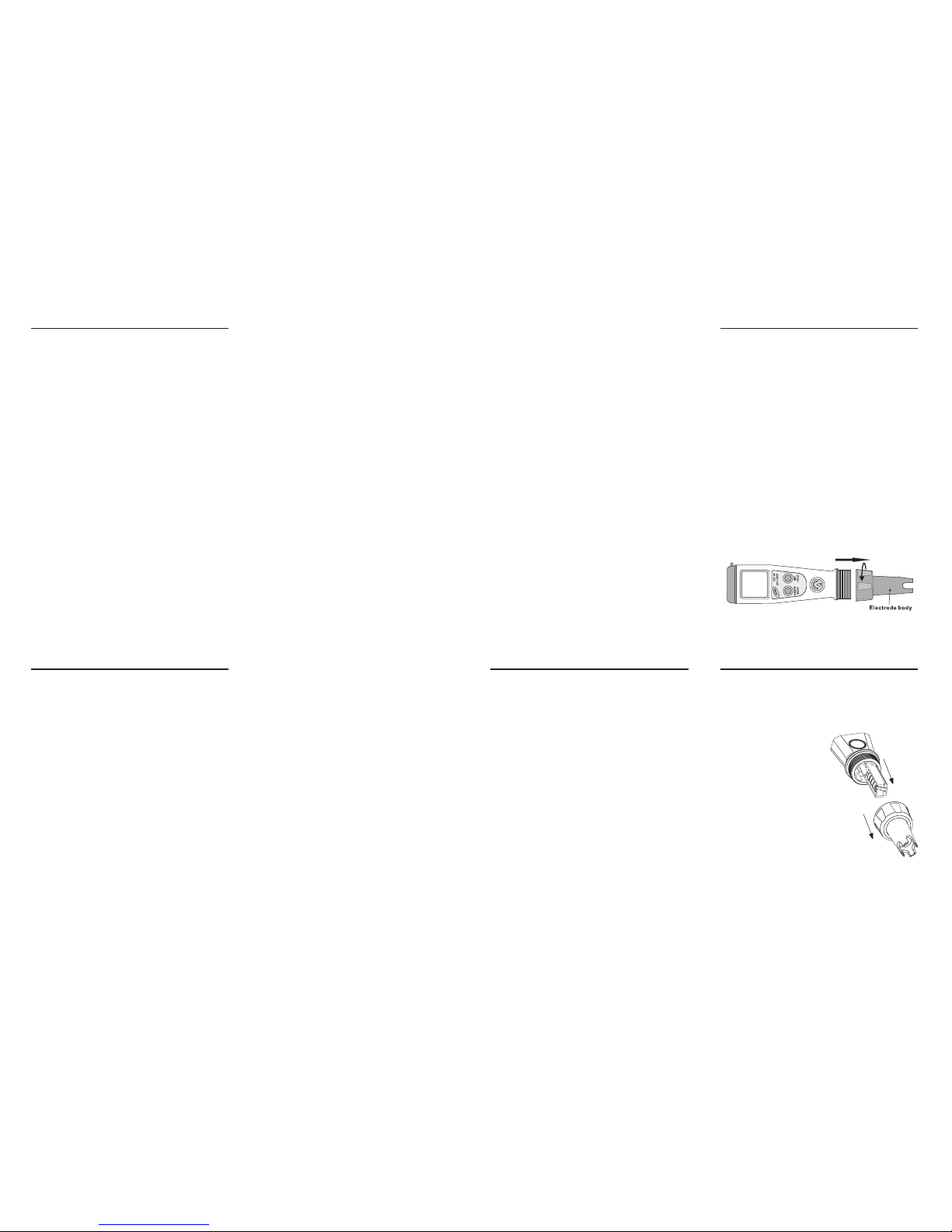
5. Electrode body
6. Battery compartment (inside)
7. Clip holder
FRONT PANEL & DISPLAY
1. Stability indicator (hourglass symbol)
2. Low battery warning indicator
3. Calibration mode / calibrated meter indica-
tion
4. ATC (Automatic Temperature Compensa-
tion) indicator
5. Secondary LCD level
6. Primary LCD level
7. Measurement unit for primary level
Dear Customer,
Thank you for choosing an Adwa product.
Pleaseread carefullythis manual before starting
operations.
This instrument is in compliance with the EMC
Directive 89/336/EEC and Low Voltage
Directive 73/23/EEC for electrical equipments.
For additional technical information, please e-
WARRANTY
ELECTRODES & SOLUTIONS
A70004P pH 4.01 buffer, 20 ml, 25 pcs
A70007P pH 7.01 buffer, 20 ml, 25 pcs
A70010P pH 10.01 buffer, 20 ml, 25 pcs
AD14P Spare pH/ORP electrode
ISTAD14 06/07
TURN THE METER ON
• Press and hold the ON/OFF/MODE button
untilthe LCD lights up.Alltheused segments
will be visible for one second (or as long as
the button is pressed)
FREEZE THE DISPLAY
• While in measurement mode, press and hold
the SET/HOLD button. The reading will be
frozen on the LCD. Press any button to re-
turn to normal mode.
TURN THE METER OFF
• While in measurement mode, press the ON/
OFF/MODE button. OFF will appear on the
secondary display. Release the button.
Note: If measurements are taken in differ-
ent samples successively, rinse the
probe thoroughly to eliminate cross-
contamination. After cleaning, rinse
the probe with some of the sample to
be measured.
OPERATIONAL GUIDE
MEASUREMENT& CALIBRATION
TAKING MEASUREMENT
• Select the desired pH or ORP (mV) mode by
pressing the SET/HOLD button.
• Submerge the electrode in the solution to be
tested while stirring it gently.
• Measurements should be taken when the sta-
bility indicator (hourglass) disappears.
• The measured value is shown on the primary
LCD level while the secondary one shows
the sample temperature.
Note: Displayed pH readings are automati-
cally compensated for temperature
variations.
Note: Before taking any pH measurement,
make sure the meter has been cali-
brated (CAL tag is displayed).
Note: The ORP (mV) range is factory cali-
brated
SETUP
Setup mode allows the selection of tempera-
ture unit and pH buffer set. To enter the setup
mode, select pH mode and then press the ON/
OFF/MODE button until CAL on the second-
ary display is replaced by TEMP and the cur-
rent temperature unit (e.g. TEMP °C). Then:
For °C/°F selection:
Use the SET/HOLD button.After the tempera-
ture unit has been selected, press the ON/OFF/
MODE button to enter the buffer set selection
mode. Press the ON/OFF/MODE button again
to return to the normal measuring mode.
To change the calibration buffer set:
Aftersetting the temperature unit, themeter will
show the current buffer set: “pH 7.01 BUFF”
(for 4.01/7.01/10.01) or “pH 6.86 BUFF” (for
NIST 4.01/6.86/9.18). Change the set with the
SET/HOLDbutton, then pressON/OFF/MODE
to return to the normal measurement mode.
ELECTRODE MAINTENANCE
When not in use, rinse the electrode with water
and store it with a few drops of pH4 solution
in the protective cap.
NEVER STORE THE ELECTRODE IN DIS-
TILLED OR DEIONIZED WATER!
•If the electrode has been left dry, soak the tip
in pH4 for at least one hour to reactivate
it.
• To prolong the electrode life, it is recom-
mendedto clean it monthly by immersing the
tip in deionized water for 30 minutes.
Afterwards, rinse it thoroughly with tap
water and recalibrate the meter.
• The electrode can be easily replaced by un-
screwing the body as shown below.
pH CALIBRATION
For better accuracy, frequent calibration of the
instrument is recommended. In addition, the
instrument must be recalibrated whenever:
a) The pH electrode is replaced.
b) After testing aggressive chemicals.
c) Where high accuracy is required.
d) At least once a month.
Calibration Procedure
• Fromnormal measuring mode,press andhold
the ON/OFF/MODE button until OFF on the
secondary LCD is replaced by CAL.
• Release the button. The LCD enters the cali-
bration mode displaying “pH 7.01 USE” (or
“pH 6.86 USE” if the NIST buffer set was
selected).
• The meter automatically recognizes buffers:
if a valid buffer is detected then its value is
shown on the primary display and REC ap-
pearson thesecondary LCD level. If no valid
buffer is detected, the meter keeps the USE
indication active for 12 seconds, followed by
WRNG, indicating the bufferbeing measured
is not a valid calibration value.
Single-Point Calibration
• For a single-point calibration with buffers
pH 4.01, 9.18 or 10.01, the meter automati-
cally accepts the calibration when the read-
ingis stable. The accepted bufferisdisplayed
together with the message “OK 1” for one
second, then the meter automatically returns
to the normal measuring mode.
• If a single-point calibration with buffer pH
7.01 (or pH 6.86) is desired, then after the
calibration point has been accepted, press
the ON/OFF/MODE button to return to nor-
mal mode. The meter shows “7.01” (or
“6.86”) and “OK 1” for one second, then it
automatically returns to the normal mode.
Note: Forbetter accuracy,it is recommended
to perform a 2-point calibration.
Two-Point Calibration
• For a two-point calibration, place the elec-
trode in pH 7.01 (or pH 6.86) buffer. After
the first calibration point has been accepted,
the “pH 4.01 USE” message appears. The
messageis held for 12 seconds, unless a valid
buffer is recognized. If no valid buffer is rec-
ognized, then the WRNG message is shown.
If a valid buffer (pH 4.01, 10.01, or 9.18) is
detected, then the meter completes the cali-
bration procedure. The LCD shows the ac-
cepted value with the “OK 2” message, and
then the meter returns to the normal mode.
Note: When the calibration procedure is
completed, the CAL tag is turned on.
To quit calibration & reset to default values
• After entering the calibration mode and be-
fore the first point is accepted, you can quit
the procedure and return to the last calibra-
tion data by pressing the ON/OFF/MODE
button. The secondary LCD displays “ESC”
for one second and then the meter returns to
the normal measuring mode.
• To reset to the default calibration values,
press SET/HOLD after entering the calibra-
tion mode and before the first point is ac-
cepted. The secondary LCD displays “CLR”
for one second, the meter resets to the de-
fault calibration and the CAL tag disappears.
BATTERY REPLACEMENT
When the batteries become weak, the battery
symbol on the LCD lights up to indicate a low
battery condition. Batteries should be replaced
soon.
To change the batteries,
unscrew and release the
electrode body. Take out
the battery compartment
and carefully replace all
four batteries while pay-
ing attention to their po-
larity.
Reattach and tighten the
electrode body properly
to ensure a watertight
seal.
Other ADWA Test Equipment manuals


Popular Test Equipment manuals by other brands


Redtech
Redtech TRAILERteck T05 user manual

Venmar
Venmar AVS Constructo 1.0 HRV user guide

Test Instrument Solutions
Test Instrument Solutions SafetyPAT operating manual

Hanna Instruments
Hanna Instruments HI 38078 instruction manual

Kistler
Kistler 5495C Series instruction manual

Waygate Technologies
Waygate Technologies DM5E Basic quick start guide

StoneL
StoneL DeviceNet CK464002A manual

Seica
Seica RAPID 220 Site preparation guide

Kingfisher
Kingfisher KI7400 Series Training manual

Kurth Electronic
Kurth Electronic CCTS-03 operating manual

SMART
SMART KANAAD SBT XTREME 3G Series user manual

Agilent Technologies
Agilent Technologies BERT Serial Getting started