Hioki 3159 User manual

1
The Model 3159 Insulation/Withstanding HiTester is a hazardous instrument that generates high voltage.
For safe use, please read the “Introduction,” “Inspection,” “Safety Notes,” and “Notes on Use” in the 3159
Instruction Manual.
This document provides, as an example, a simple method for testing withstanding voltage of electrical
appliances by using the Model 3159 Insulation/Withstanding HiTester. For details on how to use the 3159,
refer to the 3159 Instruction Manual. (Insulation resistance tests can also be performed with the 3159.)
Symbols and Notations Used in this Manual
···· Indicates that incorrect operation presents an extreme hazard that could result in serious
injury or death of the user.
···· Indicates that incorrect operation presents a possibility of injury to the user or damage to the
instrument.
The Model 3159 Insulation/Withstanding HiTester is a hazardous instrument that
generates high voltage. Please use due caution when handing the 3159. To prevent
electric shock, wear high-voltage rubber gloves and electric-proof rubber boots, and
put an electric-proof rubber sheet on the work surface.
Please read this manual thoroughly to ensure safe testing.
Measurement procedure with the 3159 (This flowchart shows the procedure for using the 3159.)
If you accidentally set the wrong settings while checking the operations, turn on the main power switch
while holding down the SHIFT key to reset the system (return to initial state).
3. Preparation
Before the Test
5. Finish the Test
4. Start the Test
Prepare for withstanding voltage test.
(Connect the electrical appliance and set the
test conditions)
Start the test, taking measures to prevent
electric shock.
Set the test voltage.
Check and record the test results.
Clean up after turning off the power.
2. Simple Startup
Inspection
(From connection
to check)
Perform a simple startup inspection for safe
testing.
1. Preparation Check that you have the necessary tools for
the test.

2
(1) Before starting a test using the 3159,
check the following information regarding
the electrical appliance to be tested.
1. Test voltage
2. Reference leakage current value
(upper limit for the test)
3. Test time
4. Test points
Points to connect with test leads
(red, black) of the 3159
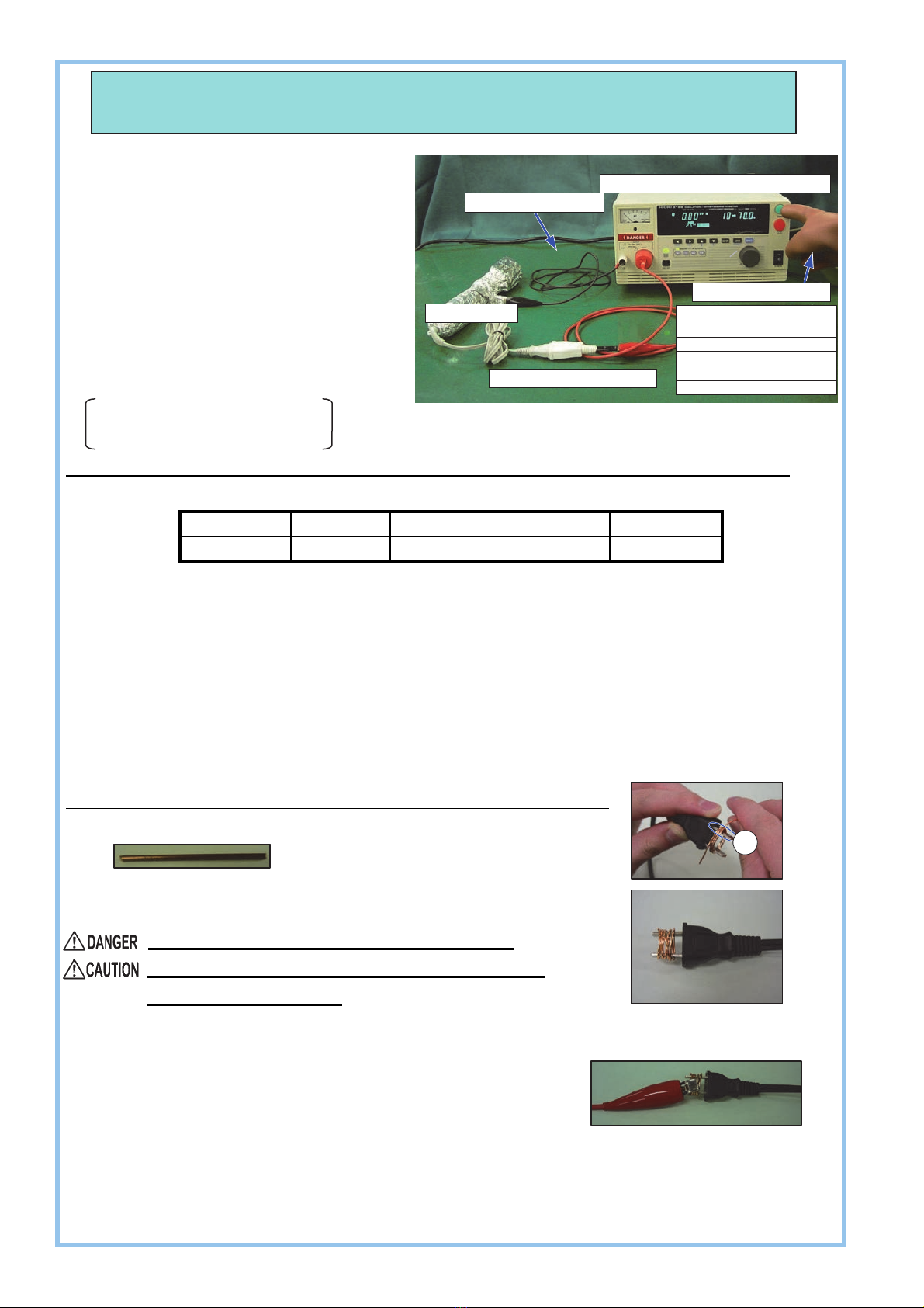
* This measurement guide explains the procedure based on an example using the following settings.
(Sample settings: Parameters and Values)
Parameter Test voltage Reference leakage current value Test time
Value 1000 V 10 mA 60 seconds
(2) Things to prepare:
1. Model 3159 Insulation/Withstanding HiTester
2. Electrical appliance to be tested
3. Rubber gloves for protection from high voltages (for safe testing)
4. Forms or a computer to record test results
5. Conductive wire (tinned wire or other non-insulated wire)
This wire is used to short-circuit the plug pins.
See figure below for details.
Short-circuit the plug pins with the conductive wire by following these steps.
1. Prepare a conductive wire.
2. Wind the wire tightly around the plug pins as shown
in the figure. Wind the wire around the pins 5 or 6 times.
Wind the wire tightly to ensure short-circuiting.
Wind the wire being careful not to bend the part of
the plug indicated by (A).
3. Check:
Conduct a final check to make sure that the wire is wound
tightly around the plug pins.
* Alternatively, use a receptacle, which is custom-made for the test, with the two leads short-circuited as
shown in the “Example test setup” above.
Electric appliance
Short-circuited receptacle
High-voltage rubber gloves
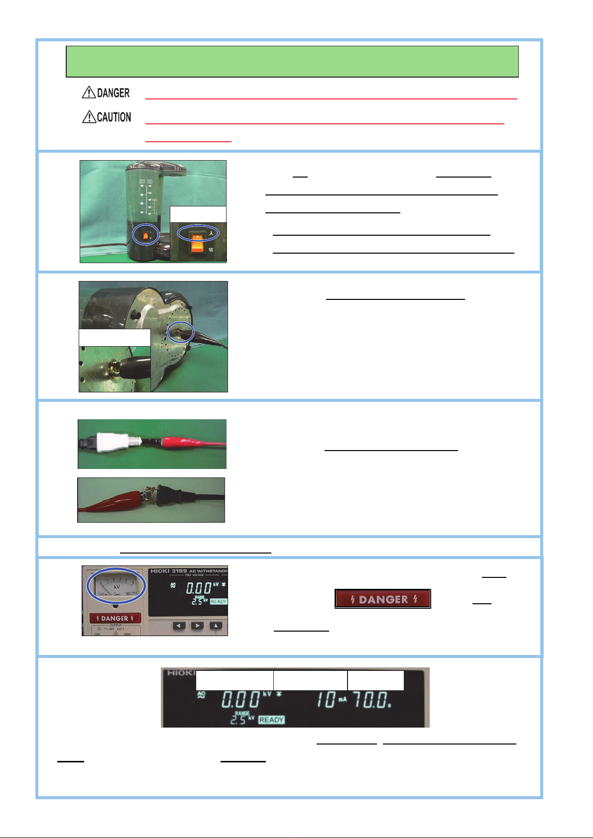
Do not perform tests in
locations that are:
• exposed to direct sunlight
• poorly ventilated
• subject to frequent mechanical vibrations
• near flammable objects
Electric-proof rubber sheet
Model 3159 Insulation/Withstanding HiTester
1. Preparation
(Example test setup)
(Short-circuited plug)
<Example>
A

3
During startup inspection, the operator intentionally applies electric current to check
whether the 3159 and the test leads are functioning properly.
(1)
(2)
(3)
(4)
Connect the power cord (supplied with the
3159) to the inlet of the main unit and a
grounded outlet.
Always properly ground the 3159 in order
to prevent electric shocks.
Short-circuit the high-voltage test lead
(red) and low-voltage test lead (black) as
shown in the picture.
Wear high-voltage rubber gloves when connecting the lead wires.
Connect the test leads securely so that they do not disconnect during the test,
Do not place the test leads directly on the ground or floor during the test. Do not
bring them into contact with any metal products in the vicinity.
Place the connected test leads on a board
made of refractory insulated material, such as
an electric-proof rubber sheet.
Check that the power switch of the 3159 is
turned off and the output voltage knob is in the
zero position.
Tightly attach the supplied low-voltage test
lead (black) to the LOW terminal (black).
Insert the supplied high-voltage test lead (red)
to the HIGH terminal (red) all the way so that it
is firmly seated.
2. Simple Startup Inspection (Connection)

4
(1)
(2)
(3) Check that
is displayed on the screen.
Take due care when the 3159 enters the READY state in which testing can start.
(4) Set the parameters as follows:
Parameter Comparative-voltage Upper limit for test Lower limit for test Test time Range
Value OFF 10 mA
OFF 70.0 seconds 2.5 kV
(5)
Check that the analog voltmeter indicates 0 kV and
that the lamp does not light
up.
Use the and keys to select range.
The selected item blinks, which indicates that it can
be edited.
Use the and keys to edit each
(6) Press the STOP (EXIT) key to confirm the test
conditions. The 3159 enters the READY state.
(The figure on the left shows the 3159 when the test
conditions have been confirmed.)
Set the test voltage using the output voltage knob after starting the test.
Check that no one is near the testing area,
and turn on the main power switch of the 3159.
Press the key and check that the lamp
lights up.
(Only the test upper limit and the test time are set here. Leave
the comparative-voltage and lower limit set to OFF.)
3. Simple Startup Inspection (Settings)
Test upper limit Test time
Test time
Before setting
Test upper limit
Comparative-voltage
Comparative-voltage
Range
Range
A
fter setting

5
(1)
(2)
(3) Inspection Result
The 3159 will beep and will be displayed on the screen.
Abnormal: will be displayed on the screen. (Perform steps (4) and (5), then follow the instruction
below.)
(4)
(5)
(6)
Wear high-voltage rubber gloves when connecting the lead wires.
Turn the output voltage knob clockwise during
the (70 second) test.
During the inspection, you do not need to adjust
the voltage accurately. As a general guide, turn
the knob about a quarter turn.
Disconnect the test leads (short-circuited part).
The startup inspection is now complete.
When a test is started, high voltage is generated by
the 3159 when it enters the state.
Do not touch the output voltage HIGH terminal (red)
or the test lead while the lamp is
illuminated.
Press the START key to start the test.
Press the STOP (EXIT) key to cancel the hold state.
*Check the test lead connections (insertion/tightening) and test again. If the result is still “PASS,” a test lead may be
damaged or the 3159 may be malfunctioning. Please contact your authorized Hioki distributor or reseller.
Turn the output voltage knob all the way
counter-clockwise, returning it to zero. Turn the
main power switch of the 3159 off.
Normal:
4. Simple Startup Inspection (Check)

6
(1)
(2)
(3)
(4)
(5)
(6)
Wear high-voltage rubber gloves when connecting the lead wires.
Connect the test leads securely so that they do not disconnect
during the test.
Connect the low-voltage test lead (black) to the
test point on the electrical appliance (surface of
the body of the appliance, ground terminal, or
other test point).
Set the three parameters mentioned in “1. Preparation”: Test voltage, Reference leakage current
value (upper limit for the test), and Test time. Refer to “3. Simple Startup Inspection (Settings).”
Set the test voltage after starting the test (while checking the measured voltage value).
Turn on the power switch of the electrical
appliance while power is not supplied to
the electrical appliance.
You cannot take accurate measurements if the
power switch of the electrical appliance is turned off.
Connect the high-voltage test lead (red) to the test
point on the electrical appliance (the short-circuited
part of the plug or the short-circuited leads of the
receptacle that is connected to the plug).
Check that no one is near the testing area and turn on the main power to the 3159.
Check that the analog voltmeter is indicating 0 kV
and that the
lamp is not
illuminated.
Measured voltage value Test timeLeakage current value
5. Pre
p
aration Before the Test
Enlarged
Switch ON

7
(1)
(2)
Set the test voltage after pressing the START key to start the test.
Check the values to be used before
p
ressin
g
the START ke
y
.
When a test is started, high voltage is generated by the 3159 when it enters the state.
Do not touch the output voltage HIGH terminal (red), test leads, electrical appliance (device to
be tested), or short-circuited receptacle while the lamp is illuminated.
The test requires the voltage to be applied for 60 seconds.
After pressing the START key, turn the output voltage knob to set the voltage
to the test voltage before the remaining time reaches 60 seconds.
To Set the Test Voltage
To set the test voltage, turn the output voltage knob while checking the
measured voltage value.
It may take time to get used to setting the test voltage.
Turning the output voltage knob excessively can raise the
voltage over the test voltage, resulting in damage to the
electrical appliance.
Press the START key to start the test.
To forcibly terminate the test process,
press the STOP (EXIT) key.
6. Start the Test
Measured voltage value Leakage current value Remaining time

8
(1) When the result is “PASS”
(2) When the result is “FAIL”
(3) If the FAIL Hold function is enabled, press the STOP (EXIT) key to cancel the hold state.
<After the test>
(1)
(2)
(3) Turn the main power switch of the 3159 off.
(4) Disconnect the electrical appliance, test leads, and power cord in the reverse order of
connection.
An "UPPER FAIL" judgment will be given and the 3159 will beep if the electric
a
pp
liance fails to withstand the test volta
g
e for the set test time.
Record the result as FAIL in the record form or other documents.
(If the measured voltage value, leakage current value, and remaining time are also
necessar
y,
record them as well.
)
Return the output voltage knob to zero. (Turn the knob
all the wa
y
counte
r
-clockwise
)
Check that the analog voltmeter indicates 0 kV and that
the
lamp is not illuminated.
To conduct further tests, start from “5. Preparation Before the Test” of this measurement guide.
A "PASS" judgment will be given if the electric appliance withstands the test voltage for the set
test time. (“PASS” will be displayed for approximately 0.5 seconds by default; however the
“PASS” indication can be retained. See “4.1 PASS Hold Function” in the 3159 instruction
manual.) Record the result as PASS in the record form or other documents.
7. Finish the Test
Measured voltage value Remaining time
Leakage current value
Measured voltage value Remaining timeLeakage current value
Other manuals for 3159
1
Table of contents
Other Hioki Test Equipment manuals
Popular Test Equipment manuals by other brands

Vlectro
Vlectro VL-AT user manual

Huazheng Electric Manufacturing
Huazheng Electric Manufacturing JY-15K manual

NEO TOOLS
NEO TOOLS 11-264 manual

Hydromotion
Hydromotion VTB1-2X instruction manual

Tektronix
Tektronix TDS5000B Series Online Programmer Guide

PCB Piezotronics
PCB Piezotronics 8159-0111A Installation and operating manual