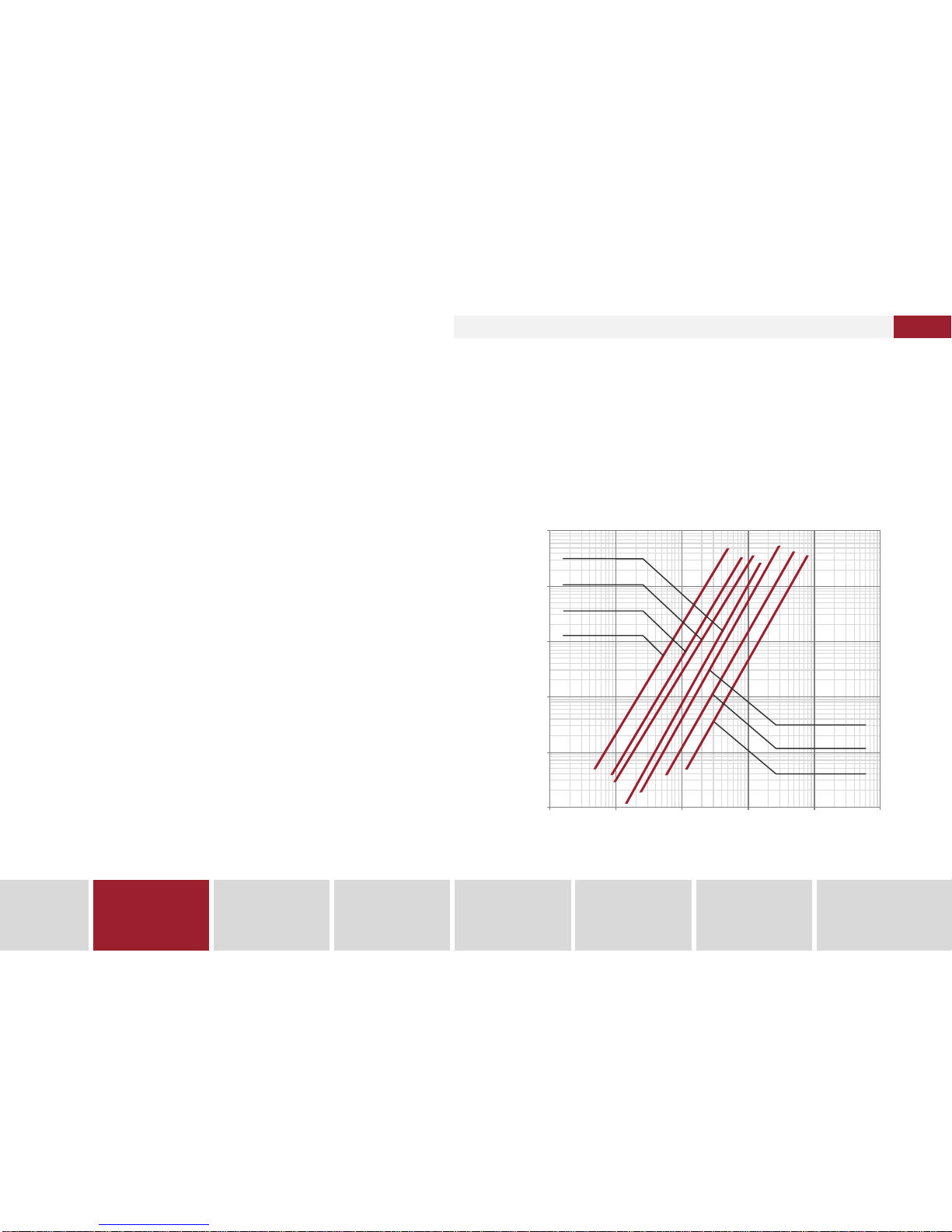
Kapat KARAT-520 User manual

OPERATIONS
MANUAL
Ultrasonic flowmeters
KARAT-520

Ultrasonic flowmeters
KARAT-520

СМАФ.407251.002 РЭ .August 2012Edition 3.0
КАRАТ-520Ultrasonic flowmeters
3
1.
Description
and operation
2.
Intended use
3.
Maintenance
4.
Verification
5.
Repair
6.
Transportation
and warehousing
7.
Utilization
INTRODUCTION
Karat-520 ultrasonic flowmeters are designed by “Uraltechnology”
RPE(ResearchandProductionEnterprise) Ltdwhichisamemberof
“Karat”RPA(ResearchandproductionAssociation).
Exclusive right of“Karat” RPAfor thisproduct isprotectedbyRussi-
anFederationLaw.
Karat-520ultrasonicflowmetersandtheircomponentpartscannotbe
reproducedorcopiedinanyform(appearance,designsolutions,soft-
ware)orbyanymeanswithoutlicenseof“Karat”RPA.
Distribution, exploitation, import, offer for sale, sale or other com-
mercialization or storage of illegally produced Karat-520 ultrasonic
flowmetersand(or)theircomponentpartsisprohibited.
Karat-520ultrasonicflowmetersareincludedinStateRegisterofmea-
suringinstrumentsunderregisternumber№44424-12(PatternApproval
CertificateofMeasuringInstrumentsRU.C.29.005.A№47132).
The present operations manual applies to all design versions of Ka-
rat-520 ultrasonic flowmeters and is intended for study of flowmeters
operation and structure. Manual also contains information required
forproperinstallation,operationandverificationoftheflowmeter.
Design of Karat-520 ultrasonic flowmeters is continuously improved
by the manufacturer, and therefore there could be insignificant diffe-
rences in device from description, mentioned in the present docu-
ment, which will not affect metrological and technical characteristics
oftheflowmeter.
n“Uraltechnology”RPELtd.isaholderf“Karat”trademark(certifi-
cate№356446dated5.08.2008)
nQualitymanagement systemof“Uraltechnology”RPE Ltd. Meet
the requirements of GOST R ISO 9001-20208 (certificate of
conformity№СДС.ТП.СМ.03238-11)
n“Uraltechnology” RPE Ltd. Is a member of “Metrology of energy
efficiency” non-commercial partnership of domestic producers
ofmeteringdevices

INTRODUCTION .............................................................................
3
TABLE OF CONTENTS ..................................................................
4
LIST OF ABBREVIATIONS AND DESIGNATIONS ........................
5
1.
DESCRIPTION AND OPERATION .................................................
6
1.1.
Purpose and application ..........................................................
6
1.2.
Design version ........................................................................
6
1.3.
Performance characteristics ....................................................
8
1.3.1.
Technological and metrological characteristics ............
8
1.3.2.
Output signals parameters ...........................................
9
1.3.3.
Power supply characteristics .......................................
9
1.3.4.
Hydraulic characteristics ..............................................
9
1.3.5.
Electromagnetic compatibility requirements ................
10
1.3.6.
Failure properties .........................................................
10
1.3.7.
External environment ...................................................
10
1.4.
Operation and description of a flowmeter.................................
11
1.4.1.
Flowmeter description ..................................................
11
1.4.2.
Measurement procedure .................................. ............
16
1.4.3.
Flowmeter operation ....................................................
16
1.5.
Marking and sealing ................................................................
28
1.5.1.
Marking ........................................................................
28
1.5.2.
Sealing .........................................................................
28
1.6.
Packing and scope of delivery ................................................
29
1.7.
Warranty ..................................................................................
29
2.
INTENDED USE ................................................ ............................
30
2.1.
Operating limitations ....................................................... ......
30
2.2.
Recommendations for choosing a flowmeter ........................
30
2.3.
Preparation for use ...............................................................
31
2.3.1.
General requirements ................................................
31
2.3.2.
Preparation for installation .........................................
32
2.3.3.
Instructions for flowmeters installation ................ .......
32
2.3.4.
Installation work ..................................................... ....
35
2.3.5.
Electric installation work ............................ ................
38
2.4.
Flowmeters use ............................................... ......................
39
2.4.1.
Commissioning ..........................................................
39
2.4.2.
Exploitation ................................................................
39
3.
MAINTENANCE ........... ....................................................... ..........
41
4.
VERIFICATION ..................................................................... .........
43
5.
REPAIR ........................................... ..............................................
45
6.
TRANSPORTATION AND WAREHOUSING .......................... ......
47
7.
UTILIZATION ................................... ..............................................
49
APPENDIX A – Diagram of flowmeters installation .......................
50
APPENDIX B –Pattern approval certificate of MI
of KARAT ultrasonic flowmeters in Russian Federation.................
50
СМАФ.407251.002 РЭ – Operations manual
Edition 3.0.August 2012
4
КАRАТ-520Ultrasonic flowmeters
КАRАТ RPA www.karat-npo.ru
TABLE OF CONTENTS

LIST OF ABBREVIATIONS AND DESIGNATIONS
ND
—
nominal diameter of pipeline or flowmeter;
MS
—
measuring section of pipeline;
MI
—
mounting insert in pipeline;
VM
—
verification method;
OM
—
operations manual;
SW
—
software;
FT
—
flow tube;
MI
—
measuring instruments;
EM
—
electronic module;
MD
—
maintenance documentation;
HWS
—
hot-water supply system;
SSM
—
State System for Ensuring Uniform Measurement;
LCD
—
liquid-crystal display;
SAE
—
set of attachment elements;
PET
—
piezoelectric transducer;
FC
—
flow conditioner;
PSO
—
power supply organization;
Qmax
—
maximum limit of flow measurement;
Qmin
—
minimum limit of flow measurement;
Qnom
—
rated flow;
Qt
—
transition flow rate.
СМАФ.407251.002 РЭ .August 2012Edition 3.0
КАRАТ-520Ultrasonic flowmeters
5
1.
Description
and operation
2.
Intended use
3.
Maintenance
4.
Verification
5.
Repair
6.
Transportation
and warehousing
7.
Utilization

1. DESCRIPTION AND OPERATION
1.1. Purpose and application
KARAT-520 ultrasonic flowmeters are designed for industrial and
commercial metering of volume flow and liquid volume in filled pipe-
lines of heating systems, cold and hot water supply under conditions
of round-the-clock service. The flowmeters can be used as a part of
heatmetersormeasuringsystems.
1.2.Design version
Flowmeters are devices
whichmeasureflowrateandvolume.
The present devices are produced in accordance with technical re-
quirementsTR4213-009-32277111-2012.
Asfor design the flowmeters differinnominaldiameter, power supply
type, output signals type (or types combination), construction of mo-
untingelements.
microprocessormeasuring and calculating
КАRАТ-520
-
ХХ
-
Х
-
АR
Flowmeter
description
Dimension type
of the flowmeter (ND):
, , , , , ,20 25 32 40 50 65 80
Design variant of the flowmeter:
, , , ,
0 1 2 3 4
Additional functions:
—the flowmeter has flow archives ( in the absence of
symbol, there are no archives in the flowmeter)
—the flowmeter has normalized characteristics
of reverse flow measurement (in the absence of symbol
characteristics of reverse flow measurement are not
normalized)
A A
RR
Flowmeters designation in technical and maintenance documenta-
tion of“Uraltechnology”RPEisthefollowing:
СМАФ.407251.002 РЭ – Operations manual
Edition 3.0.August 2012
6
КАRАТ-520Ultrasonic flowmeters
КАRАТ RPA www.karat-npo.ru

Figure 1.2 – Appearance of KARAT-520 -50, -65, -80 ultrasonic
flowmeter
Figure 1.1 – Appearance of KARAT-520-20, -25, -32, -40
ultrasonic flowmeter
Table 1.1 –Design variants of KARAT-520 flowmeter
Design variant
0
1
2
3
4
Built-in battery 3.6 V
+
External power supply (24 ± 12) V
+
+
+
+
Digital interface RS-485
+
Digital interface M-Bus
+
Current output 4-20 mA
+
Pulsed output
+
+
+
+
+
KARAT-520-20, -25, -32, -40 flowmeters are thread (nipple) moun-
ted;it means that theyareinstalled on the pipelines bymeansof con-
nectors (nipples) and coupling nuts. KARAT-520-50, -65, -80
flowmetersareflange mounted; they are installed on the pipelines by
meansofflanges.
KARAT-520appearanceispresentedonthefigures1.1and1.2.
СМАФ.407251.002 РЭ .August 2012Edition 3.0
КАRАТ-520Ultrasonic flowmeters
7
1.
Description
and operation
2.
Intended use
3.
Maintenance
4.
Verification
5.
Repair
6.
Transportation
and warehousing
7.
Utilization

1.3.Performance characteristics
1.3.1.Specification and metrological performance
Flowmeters have the specified technical and metrological character-
istics,whicharementionedbelow.
Water or other nonaggressive fluid with the following characteristics
isusedasaworkingfluidintheflowmeters:
3
nworking fluid density, kg/m ……..................……………700–1200;
2–6–6
nkinematic viscosity of a working fluid, m /s.....0,19•10 — 1.7•10 ;
ntemperature, °C …………………………..........………...…...1–150;
nmaximumworking pressure, MPa ……......................................1,6;
nsolidsandgasesconcentration,%ofthevolume,notmorethan.....1
Table1.2 – The range of measured flow and pulse weight
Dimension
type of
a flowmeter
3
Flow range limit, m /h
Pulse weight,
l/pulse
Qmin
Qt
Qnom
Qmax
КАRАТ-520-20
0,025
0,050
2,5
5,0
0,1
КАRАТ-520-25
0,035
0,070
3,5
7,0
1,0
КАRАТ-520-32
0,060
0,120
6,0
12,0
1,0
КАRАТ-520-40
0,100
0,200
10,0
20,0
1,0
КАRАТ-520-50
0,150
0,300
15,0
30,0
1,0
КАRАТ-520-65
0,250
0,500
25,0
50,0
1,0
КАRАТ-520-80
0,400
0,800
40,0
80,0
10,0
Table 1.3 – Overall dimensions and weights
Dimension
type of
a flowmeter
Overall dimensions, mm, not more than
Weight, kg,
not more
than
Length
Width
Height
КАRАТ-520-20
190
100
150
1,5
КАRАТ-520-25
260
100
150
2,0
КАRАТ-520-32
260
100
150
2,2
КАRАТ-520-40
300
160
200
5,2
КАRАТ-520-50
300
180
200
7,3
КАRАТ-520-65
300
200
220
9,4
КАRАТ-520-80
300
220
220
12,1
Table 1.4 – Limits of permissible relative error
Measured flow
range
Limits of permissible relative error, % during
measurement:
flow and
volume
measurement
by digital
output
volume
measurement
by pulse output
flow
measurement
by current
output
from Q to Q
t max
± 1,0 (± 2,0)
± 1,0 (± 2,0)
± 1,0 (± 2,0)
from Q to Q*
min t
± 2,0 (± 3,0)
± 2,0 (± 3,0)
± 2,0 (± 3,0)
Permissiblerelativeerrorlimits duringtime measurementaccount for
±0,01%.
*Q value is not included in the mentioned measuring span.
t
—
Comment
In case of flow rate and volume measurement of forward flow,
permissible relative error limits are indicated without brackets,
otherwise(reverseflow)—inbrackets.
СМАФ.407251.002 РЭ – Operations manual
Edition 3.0.August 2012
8
КАRАТ-520Ultrasonic flowmeters
КАRАТ RPA www.karat-npo.ru

3
Flow rate, m /h
100
10
1
0,1
0,01
0,0010,01 0,1 110 100 1000
Pressure loss, MPa
Figure 1.3 – Pressure loss nomogram for KARAT-520 flowmeters
КАRАТ-520-20КАRАТ-520-20
КАRАТ-520-80КАRАТ-520-80
КАRАТ-520-25КАRАТ-520-25
КАRАТ-520-32КАRАТ-520-32
КАRАТ-520-40КАRАТ-520-40
КАRАТ-520-50КАRАТ-520-50
КАRАТ-520-65КАRАТ-520-65
1.3.2.Output signals parameters
Flowmeters of all design variants have 2 galvanically isolated pulse
outputs for transmission of measured values in the form of pulse
signalswiththespecifiedpulseweight(table1.2).
Pulsesignalhasthefollowingcharacteristics:
nminimumpulse-repetition interval...........................................…62;
npulse duration, ms ……………....................………................….31;
nvoltageinoutputcircuit,V,notmorethan………............…..…….50;
nminimumcurrent,providedin anoutputcircuit,mA.......................2;
nmaximumswitching current inanoutput circuit, mA…................10.
Flowmeter of KARAT-520-ХХ-3 design version has 2 analog elements
with current signal parameters according to GOST 26.011(“Measuring
and automation devices. Input and output current and voltage continu-
oussignals”):
nOutputcurrent,mA…....................................................…......4–20;
nSupply voltage, V ..................................................…....……12–36;
nMaximumloadresistance, Ohm…........................................…100.
FlowmetersofKARAT--520-ХХ-1,KARAT-520-ХХ-2designversions
withdigital outputRS-485, M-Bushavethe outputsignalparameters,
whichmeet therequirements, mentionedinstandards forthepresent
interfaces.
1.3.3.Powersupplycharacteristics
Inaccordancewith design version (table 1.1) flowmeters can be sup-
plied both from internal and external power sources according to de-
signversion.
Flowmeters of design version (it.1.2) are supplied from built-in lith-
ium battery of “C” dimension type with voltage equal to 3.6V ± 0,2V
and capacity equal to 7.2Ah. Battery life accounts to not less than 4
yearsofflowmetercontinuousrunning.
0
Flowmetersof , ,,designversionsaresuppliedfromexternaldirect
current source with output voltage from 12 to 36V. The output current
ofapowersourceshouldcorrespondtothefollowingcharacteristics:
nitshouldbenotlessthan100mAfor and designversions;
nnotlessthan50mAfor designversion;
nnotlessthan10mAfor4designversion.
1.3.4.Hydrauliccharacteristics
Diagrams of pressure loss dependence on the flow rate in flow tubes
fordifferentdimensiontypesaregivenonfigure1.3
1 2 3 4
1 2
3
СМАФ.407251.002 РЭ .August 2012Edition 3.0
КАRАТ-520Ultrasonic flowmeters
9
1.
Description
and operation
2.
Intended use
3.
Maintenance
4.
Verification
5.
Repair
6.
Transportation
and warehousing
7.
Utilization

1.3.5.Electromagnetic compatibility requirements
Flowmetersareresistanttothefollowingtypesof electromagnetic in-
terferences:
nelectrostatic dischargesinaccordancewith GOST R 51317.4.2 (“Elec-
tromagnetic compatibility of technical equipment. Electrostatic dis-
charge immunity. Requirements and test methods”) with parameters
definedin5clauseofGOSTR51649(“Heatmetersforwaterheatsup-
plysystems.Generalspecifications”)and6.13clauseofGOSTREN
1434-4(“Heatmeters.Part4:Testsfordesignapproval”);
nnanosecond pulse interferences with 3 test level for alarm circuits
andbeingbetterthanCclassbyperformancecriteriainaccordance
with GOST R 51317.4.4 (“Electromagnetic compatibility of techni-
cal equipment. Immunity to nanosecond impulsive disturbance.
Requirementsandtestmethods”);
nmicrosecondpulse interferences ofhighenergy with 2 testlevel for
alarm circuits being better than C class by performance criteria in
accordance with GOST R 51317.4.5 (“Electromagnetic compatibil-
ity of technical equipment. Microsecond high energy pulse distur-
banceimmunity.Requirementsandtestmethods”).
Intensity of man-made interference field, generated by flowmeters,
doesn'texceed values, specified in GOST R 51318.22 (“Electromag-
netic compatibility of technical equipment. Information technology
equipment.Man-maderadiodisturbance.Limitsandmethodsofmea-
surement”) with parameters specified in 5 clause of GOST R 51649
(“Heat meters for water heat supply systems. General specifica-
tions”)andGOSTREN1434-4(“Heatmeters.Part4:Testsfordesign
approval”).
1.3.6.Failure properties
Mean time between failures of the flowmeters accounts for
50000hours.Meanlifetimeoftheflowmetersaccountsfor12years.
Storagetimeofserviceandarchivaldatainnonvolatilememoryofthe
flowmeterisnotlimited.
1.3.7.External environment
Flowmeters maintain their metrological and performance character-
isticswhenoperatinginthefollowingconditions:
nambienttemperature, °C;
nrelativehumidity at 35°C, % .................................not more than 80;
nbarometric pressure, kPa ................................................84–106,7.
Flowmeters are resistant to sinusoidal vibration with frequency in the
10 to 55 Hz range, displacement amplitude equal to 0.35 mm, by N2
group in accordance with GOST R 52931 (“Instruments for process
monitoringandcontrol.Generalspecifications”)
EM body protects electronic components from foreign objects, dust
andwatereffectinaccordancewithGOST14254–IP65(“Degreesof
protectionprovidedbyenclosures(IPcode)”).
…….……...................................…..1–55
СМАФ.407251.002 РЭ – Operations manual
Edition 3.0.August 2012
10
КАRАТ-520Ultrasonic flowmeters
КАRАТ RPA www.karat-npo.ru

1.4.Operation and description of a flowmeter
1.4.1. Flowmeter description
Flowmeters are produced in accordance with requirements of GOST
R EN 1434. In general, the flowmeter comprises an assembly of flow
tube FT and electronic module EM, integrated in a single device, see
figure1.4.
EMapparatus isidenticalfor all dimensiontypesand design versions
oftheflowmeters.DimensiontypesdifferinFTstructure.
DiversityinFTstructureis causedbyfluiddynamicproperties inpipe-
linesofdifferentdiameters.
FTaremarkedinaccordancewith1.6.1clauseofthepresentOM.
Figure 1.4 – KARAT-520 flowmeters
1—electronic module; 2—marking; 3—pulse output wire; 4—interface module wire; 5—flow tube;
1
5
3
4
Thread mounted Flange mounted
2
1
5
3
4
2
СМАФ.407251.002 РЭ .August 2012Edition 3.0
КАRАТ-520Ultrasonic flowmeters
11
1.
Description
and operation
2.
Intended use
3.
Maintenance
4.
Verification
5.
Repair
6.
Transportation
and warehousing
7.
Utilization

FTstructure of thread and flange mounted flowmeters is given on 1.5
and1.6figures.
FTbodiesaremadeof brassbycasting withsubsequenthotpressing
andprecisionsurfacing.
All EM are fastened on the FT. There are 2 piezoelectric transducers
(PET)inFT(2calloutonfigure1.5and1.6),eachofthemactsasboth
transmitterandreceiver.ThereareplastictubesinsideFT,witchdiffer
inaccordancewithdimensiontype.
The ultrasonic sound in KARAT-520-20, -25, -32 flowmeters is send
alongtheFT axe fromonetransducertoanother. Piezoelectric trans-
ducers(2callout,figure1.5)arelocatedinsidetheFT.
Plastic tube (3 callout, figure 1.5) has rhombic cross-section. Flow
nonuniformity is concentrated in the rhomb angles. Plastic tube, PET
andtubeflaringinthelowendoftube(4callout,figure1.5)actasflow
straighteners, as the result, velocity profile of working fluid remains
symmetricanduniform.
There is a flow conditioner (1 callout, figure 1.6) in KARAT-520-40,
-50, -65, -80 flowmeters, which reshapes velocity profile after distur-
bances,locatedupstreamthemeter.
Plastic tube (3 callout, figure 1.6) has hexagonal cross-section.
Thereby, flow nonuniformity is concentrated in the hexagon angles,
velocityprofileofworkingfluidremainssymmetricanduniform.
Transducers(2callout,figure1.6)andreflectors(4callout, figure1.6)
are located inside the FT. Reflectors serve to direct an ultrasonic
beamatanangletothemeasuredflowdirection.
Electronic module of a flowmeter (figure 1.7), connected to FT by a
metalplate,ismadeofshockresistantplastic.EMbodybottompartis
made of plastic with low thermal conductivity. There is an air gap be-
tweenbottompartofEMbodyandametalplate,thereforeheattrans-
ferfromaplatetoflowmeterbodyisreduced.
Datacables(3and4calloutsonfigure1.4)aremadewithisolationofsili-
conematerial,itensureshightemperaturestrength.Inaccordancewith
flowmeterdesignversion(1.1table)2or3cablesareconnectedtoEM.
Cables are routed through mechanical seals located in EM body bot-
tompart.Datacable(3callout)is connectedto thepulse outputof de-
vice. Digital (RS-485, M-Bus) or analog module (current output) are
connectedbymeansofthedata cable(4 callout).Flowmeter connec-
tion to external power supply is also provided by the data cable
(4callout).
Top part of EM body, made of transparent plastic, covers electronic
module of device, where LCD (2 callout, figure 1.7) is located.
MeasurementdataandsettingsaredisplayedonLCD.
Holesfor sealing (1 callout, figure 1.7) are locatedattheedges of EM
coverandtoppartofEMbody.
Sealingrestrictsuseraccesstodevicewhichisputinoperation.
Technological module (11 callout, figure 1.7) is located in the top part
of EM body. In accordance with flowmeter design version (1.1 table)
technologicalmodulecomprises:eitherbuilt-inbattery ordigital inter-
faces modules (RS-485, M-Bus), or current output module. Built-in
batteryisconnectedtoasocket(12callout,figure1.7).Interfacemod-
ules and current output module are also connected to a socket
(10callout,figure1.7).
СМАФ.407251.002 РЭ – Operations manual
Edition 3.0.August 2012
12
КАRАТ-520Ultrasonic flowmeters
КАRАТ RPA www.karat-npo.ru

Figure 1.6 – FT description of KARAT-520-40*, -50,
-65, -80 flowmeters
1 — flow conditioner;2 — PET transducer;3 — plastic tube; 4 — reflectors
* – KARAT-520-40* flowmeters are thread mounted (1.2 section of the manual)
Figure 1.5 – FT description of KARAT-520-20,
-25, -32 flowmeters
1 — built -in straight piping 2 ND; 2 — PET transducer; 3 — plastic tube;
4 — tube flaring in the low end of tube
23
4
1223
1 2
4
СМАФ.407251.002 РЭ .August 2012Edition 3.0
КАRАТ-520Ultrasonic flowmeters
13
1.
Description
and operation
2.
Intended use
3.
Maintenance
4.
Verification
5.
Repair
6.
Transportation
and warehousing
7.
Utilization

14
Расходомер-счетчикКАРАТ-520
Сделанов России
ДУ
Диапазонрасхода: мин
Зав.№
,макс м/ч
3м/имп
3
Весимпульса
МПаPмакс
3
m
1
21
5
13
3 4
Figure 1.7 – Electronic module appearance
Flowmeters have direct and reverse pulse outputs.Devices marked
with “R” symbol have normalized metrological characteristic in case
ofreverseflow.
Galvanic separation (optocoupler) allows to separate external com-
municationlinefrominternalcircuitofaflowmeter.
СМАФ.407251.002 РЭ – Operations manual
Edition 3.0.August 2012
14
КАRАТ-520Ultrasonic flowmeters
КАRАТ RPA www.karat-npo.ru
Set h
3
m /h
Ultrasonic flowmeter
КАRАТ-520-20-0 3
Q, m /h
3V 0,05W
Made in Russia

1 1
ВРК
А
3
m /h
3
m
h
6
2
7
8
910
11
12
8
1 — holes for sealing; 2— liquid-crystal display; 3— bottom part of EM body; 4— top part of EM body; 5— EM cover;
6— QCD (Quality Control Department) seal from manufacturer; 7— protection seal with verification mark; 8— holes for sealing;
9— start-button for settings viewing; 10 — socket for interface or analog modules connection;
11 — technological module; 12 — socket for internal power source connection; 13 — place for magnet application; 14 — flowmeter nameplate
Figure 1.7 (end) –Electronic module appearance (without top cover)
СМАФ.407251.002 РЭ .August 2012Edition 3.0
КАRАТ-520Ultrasonic flowmeters
15
1.
Description
and operation
2.
Intended use
3.
Maintenance
4.
Verification
5.
Repair
6.
Transportation
and warehousing
7.
Utilization
Set
URALTECHNOLOGY

1.4.2. Measuring principle
The flow meter operates by alternately transmitting and receiving a
burst of sound energy between two piezoelectric transducers and
measuringthetransittimethatittakesforsoundtotravelbetween the
two transducers. Difference in the measured transit time is directly
andexactlyrelatedtovelocityofliquidinthepipe.
1.4.3.Flowmeter operation
The flowmeter measures working fluid flow rate and volume in FT.
MeasureddataisdisplayedontheflowmeterLCD (figure1.8),thanit
istransferredbypulseoutputstorecordingunit;ifthereisaninterface
moduleinthemeterthemeasureddataisarchived.
IndicationonLCDis automaticallyenabled incase offlowmeter filling
with water. In case of water drain from FT indication on LCD is dis-
abled. Information changes every 3–4 seconds, subsequently dis-
playingthefollowingparameters: 3
ninstantaneousflowrateofworkingfluid,m /h;
3
ncumulativevolumeinforwarddirection,m ;
3
ncumulativevolumeinreversedirection,m ;
noperatingtimestartingfromthetimeofmeterinstallation,h.
Microprocessor integrated in EM calculates the time difference and
then flow rate and volume of working fluid by the measured times in
bothdirections.
3
m /h
3
m
h
Set
1 2
7 6 5 4 3
Figure 1.8 – LCD appearance
1region –displays parameter value.
It comprises up to 8 displayed characters. The “arrow” indicator points to the
displayed parameter.
2region —device type.
3region —pattern approval mark of measuring instruments.
4region —instantaneous flow rate.
5region —cumulative volume.
6region —operating time.
7region —flowmeter parameters
СМАФ.407251.002 РЭ – Operations manual
Edition 3.0.August 2012
16
КАRАТ-520Ultrasonic flowmeters
КАRАТ RPA www.karat-npo.ru

Sequenceofparameterschange mentionedaboveiscalledstandard
displaymode.
The present display mode is indicated on LCD on default in case of
flowmeter switching on. The sequence of parameters displaying is
givenonfigure1.9.
In addition a mode of extended display precision can be indicated on
LCD. Extended display precision mode differs from standard mode
by other cumulative volume representation. Representation of in-
stantaneousflowrateandoperatingtimeisidenticalinbothmodes.
Cascadeswitchingof mentionedmodes allowstoreadthevaluesof
cumulative volume from LCD with precision corresponding to speci-
fied metrological device characteristics (1.4 table), regardless of the
numberofsignificantdigitsofdisplayedparameter.
Extendeddisplayprecisionmodeisswitchedonbyoneof2methods:
nBy means of magnet application (not less than 3 seconds) to
selected place on a flowmeter nameplate (13 clause, figure 1.7)
underwhichmagneticallyoperatedsealedswitchislocated;
nBymeans of long pressing (not lessthan3seconds) of settings dis-
play button (9 clause, figure 1.7) in case of uncovered EM of
flowmeter.
Figure 1.9 – Parameters indicated on LCD during standard
displayed mode
*— is indicated only in case of nonzero value
Operating time
Cumulative reverse volume*
Instantaneous flow rate
Set h3
m3
m /h
Cumulative forward volume
3–4 sec3 4 sec–3 4 sec–
Warning!
Parameters displayed on LCD are indicated accurate to 7 signifi-
cant digits (characters). Eighth digit is used for indication of display
modes.
Note!
Incase of settings button pressing or magnet application all“arrow”
indicatorsaresimultaneouslydisplayedonLCD(figure1.8).
СМАФ.407251.002 РЭ .August 2012Edition 3.0
КАRАТ-520Ultrasonic flowmeters
17
1.
Description
and operation
2.
Intended use
3.
Maintenance
4.
Verification
5.
Repair
6.
Transportation
and warehousing
7.
Utilization
Set h3
m3
m /h
Set h3
m3
m /h
Set h3
m3
m /h

Standard display mode Extended display precision mode
or
5 display cycles
3–4 sec3–4 sec3 4– sec
Magnet Settings display button
Figure 1.10 – Sequence of display modes viewing
Duringextendeddisplayprecision modeparametersareindicatedon
LCD every 3-4 seconds. Standard display mode is switched automati-
callyafter5cyclesofmeasuredparametersdisplay,figure1.10
3–4 sec 3–4 sec 3–4 sec
СМАФ.407251.002 РЭ – Operations manual
Edition 3.0.August 2012
18
КАRАТ-520Ultrasonic flowmeters
КАRАТ RPA www.karat-npo.ru
Set h3
m3
m /h
Set h3
m3
m /h
Set h3
m3
m /h
Set h3
m3
m /h
Set h3
m3
m /h
Set h3
m3
m /h
Set h3
m3
m /h
Set h3
m3
m /h

Instantaneous flow rate represents a current flow rate value of work-
ingfluid.
The present parameter is displayed on LCD with 5 significant digits.
Examplesofinstantaneousflowratearegivenonfigure1.11.
Figure 1.11 –Displaying of instantaneous flow rate value
3
Instantaneous flow rate is m /h0,0000
Set h3
m3
m /h
3
Instantaneous flow rate is m /h10,000
3
Instantaneous flow rate is m /h100,00
СМАФ.407251.002 РЭ .August 2012Edition 3.0
КАRАТ-520Ultrasonic flowmeters
19
1.
Description
and operation
2.
Intended use
3.
Maintenance
4.
Verification
5.
Repair
6.
Transportation
and warehousing
7.
Utilization
Set h3
m3
m /h
Set h3
m3
m /h

Cumulative forward volume represents the value of working fluid
volume,accumulatedsincedeviceinstallationincaseofforwardflow.
ThepresentparameterisindicatedonLCDinbothdisplaymodes.
In standard display mode cumulative volume is indicated on LCD
starting from 5 significant digits accurate to 4 digits after decimal
3
point. If the value exceeds 1000 m cumulative volume value is
indicatedaccurateto3digitsafterdecimalpoint. Ifthevalueexceeds
3
10 000 m cumulative volume value is indicated accurate to 2 digits
afterdecimalpointandsoon(figure1.12).
Figure 1.12 –Standard mode of data display on LCD
Cumulative volume value is displayed accurate to 4 digits after decimal point
Cumulative volume value is displayed
accurate to 3 digits after decimal point Cumulative volume value is displayed accurate to zero
digits after decimal point
СМАФ.407251.002 РЭ – Operations manual
Edition 3.0.August 2012
20
КАRАТ-520Ultrasonic flowmeters
КАRАТ RPA www.karat-npo.ru
Set h3
m3
m /h
Set h3
m3
m /h
Set h3
m3
m /h
Set h3
m3
m /h
Table of contents
Popular Measuring Instrument manuals by other brands

Hanna Instruments
Hanna Instruments HI 95761C instruction manual

KBR
KBR F96 TFT- -5 Series user manual

Ecolab
Ecolab Nalco Water STORM Settling Rate Monitor Installation, operation & maintenance manual

Matelec
Matelec FKW 15120 user manual

Leuze
Leuze AMS 301i Original operating instructions

Crouzet
Crouzet CTR24L-2513 operating instructions

Luster Leaf
Luster Leaf 1835 user manual

Ocean Optics
Ocean Optics MFPF100-1 Installation and operation manual

Industrial physics
Industrial physics sheen DV2300 operating instructions

Burkert
Burkert ELEMENT 8228 operating instructions

Colibri
Colibri SMARTHUB user manual

Avisoft
Avisoft UltraSoundGate 416-200 user guide