Karassn KS-200B Series User manual

KS-200B Series
Wireless Alarm System
User Manual
Karassn Security Electronics Co. Ltd

Table of Contents
I. Introduction..........................................................................(1)
II. Definition............................................................................(3)
III. Precautions of Operation.....................................................(4)
IV. Main Functions and Characteristics......................................(4)
V. Name and usage of main parts................................................(5)
VI. Interface performance and system connection.....................(10)
VII. System installation..........................................................(10)
VIII. Operation Guide............................................................(12)
IX. Main Technical Specification............................................(21)
X. Optional parts list..............................................................(22)
XI. Simple Failure Recovery...................................................(23)
We are honored that you select Karassn security products, thank
you very much. To make full use of its performance and keep
stability, please carefully read this "User's Manual" before
operation. For any question, please don't hesitate to contact
Karassn Client Service Department or Agents.

I. Introduction
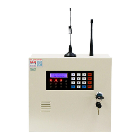
KS-200B computer-controlled wireless alarm system is a type of
long-distance wireless alarm system, which is composed of an
alarm host and 1 to 100 detectors. All these constitute a complete set
of region alarm service system which can be widely used for
industrial and mining enterprises, schools, warehouse, villas, office
buildings and other attended locations.
System composition
KS-200B alarm system is composed of KS-200BM computer-
controlled wireless alarm host, KS-200 series wireless infrared
detector and KS-50 series wireless emitter (as shown in the
following figure)
1.Alarm host
KS-200BM alarm host adopts second-super processing technology
and the core is an 8-bit single chip. It has the advantages of high
receiving sensibility, simple operation, powerful functions and
stable performance.
KS-200BMI alarm host adopts second-super processing technology
and the core is an 8-bit single chip. It has the advantages of high
receiving sensibility, simple operation, powerful functions and
stable performance. Otherwise, It has auto dialer and alarm
information voice function.
2.Wireless infrared detector
KS-200AT wireless infrared detector adopts double infrared
inductor together with special infrared processing integrated circuit
as well as the automatic temperature compensation technology,
which make it have the advantages of low error alarm ratio and high
anti-interference capability. KS-200AT-C infrared detector is with
built-in batteries for backup power. It also has rechargeable

function and can switch between AC and DC.
KS-200AT /KS-200ACT
Wireless infrared detector
ĂĂ
ĂĂ
ĂĂ
.$5$6616(&85,7<3527(&7,21(/(&7521,&6&/7'
KS-200ATI
Wireless infrared detector
KS-200DCT
KS-200ECT
KS-200FCT
Wireless infrared detector
KS-200BTI
Wireless infrared detector
KS-200BCT
Wireless infrared detector
KS-10A
KS-10B
wireless remote controller
KS-10A
KS-10B
wireless remote controller
KS-200DCT
KS-200ECT
KS-200FCT
Wireless infrared detector
KS-200BW
Wireless door sensor
wireless caller
wireless urgent key
KS-200BW
Wireless door sensor
KS-50A Wireless emitter
KS-50AI
Wireless emitter
Urgent key
Wire
Wire
Active infrared dedector
Wire
Infrared & microwave
motion dedector
wireless smoke detector
Telephone office
Telephone Pager Mobile phone
,4#$PNQVUFS$POUSPMMFE8JSFMFTT"MBSN4ZTUFN
ORIENTATION
TIME

KS-200ACT wireless infrared detector adopts double infrared
inductor together with single chip processing technology as well as
the automatic temperature compensation technology, which make it
have the advantages of low error alarm ratio and extremely high
anti-interference capability. KS-200ACT-C infrared detector is
with built-in batteries for backup power. It also has rechargeable
function and can switch between AC and DC.
Except for the functions of KS-200ACT detector, KS-200ATI
wireless infrared detector also has wireless remote-controlled
defense and defense-deactivation functions and wireless
forwarding function, which can work with together with low power
detector and remote controller. Otherwise, KS-200ATI-C infrared
detector is with built-in batteries for backup power. It also has
rechargeable function and can switch between AC and DC. And it
has low voltage of batteries indictor.
Based on KS-200ACT, KS-200BCT wireless infrared detector adds
30-second on-site alarm function. Otherwise, KS-200BTI-C
infrared detector is with built-in batteries for backup power. It also
has rechargeable function and can switch between AC and DC. And
it has low voltage of batteries indictor.
Compared to KS-200ATI, KS-200BTI wireless infrared detector
adds 30-second on-site alarm function. Otherwise, KS-200BTI-C
infrared detector is with built-in batteries for backup power. It also
has rechargeable function and can switch between AC and DC. And
it has low voltage of batteries indictor.
II. Definition
Wireless forwarder
The detector (emitter) with wireless forwarding function, forward
one group given address code which is the wireless signal of short-
distance to KS-200BM alarm host to recognize the alarm signal.

The advantage of this function is to come true the wireless relaying
emitter and decrease the system cost. For example, the users have to
install 10 detectors for one floor. Usually, It need to 10 KS-200ACT
detectors and 10-backup power for these detectors and AC power. If
the users use the wireless forwarding function, they just need 1 KS-
200ATI-C detector and 9 short-distance detectors (such as KS-
200DCT). It will decrease the system cost so much.
III. Precautions of Operation
1. Please carefully read the User Manual and pay more attention to
labels and directions on the user alarm host before operation. Check
whether the wiring connections are correct and then turn it on to test
so as to prevent the occurrence of accidents.
2. When the alarm host is not equipped with backup power supply
and self-propelled clock modules, the clock should be adjusted
again if a power failure occurs so as to avoid the incorrectness of the
clock.
3. The alarm host can be equipped with 12V 1.2Ah sealed-acid
storage cell. If the power failure often occurs in a defense area, the
batteries with a larger capacity are recommended to serve as the
emergency power.
4. Please don't disassemble the alarm host at will as not to cause
accidents and damage the apparatus.
5. If a failure occurs during operation, please contact with Karassn
client service department of Karassn agents with the warranty card
carried. Remember not to disassemble and repair by yourself.
6. Please periodically perform routine test so as to clear troubles in
time to avoid alarm omissions.
IV. Main Functions and Characteristics
KS-200BM system function introduction
1. The detector (wireless emitter) will automatically match codes
with the alarm host. And the system can be simply and easily
expanded.

2. 1-100 independent wireless defense area can be defined and the
defense of each defense area can be activated or deactivated
independently. Common defense area and emergent defense area
can be defined at will.
3. The alarm host has two sets of timing switch on/off time and also
current on/off status indication.
4. There are three kinds of optional alarm sounds and four levels of
optional alarm volumes.
5. Ten pieces of up-to date alarm messages can scroll to display
simultaneously.
6. The 60 latest alarm messages can be inquired.
7. Optional emergency power supply, floating charge device and
low voltage alarm function
8. A set of normal open, a set of normal close and +12V DC output
are provided to control other devices (e. g., startup alarm horn,
alarm light, alarm linkage and etc.)
KS-200BMI system function introduction
Compatible with all KS-200B function, It also extended the
following functions:
1. Automatically dial 6 groups preset telephone and inform 2 groups
pagers.
2. With intelligent dial and receiving alarm distinguishable function.
Automatically distinguish telephone line state to improve dial
speech and stability.
3. Automatically preempt to dial alarm telephone.
4. With the dial pause function, can be compatible with exchange
system. 5. Can be record 10 seconds alarm voice, and automatically
play back pre-record voice and report alarm zone when alarm occurs.
6. Can startup/shut down the phone line in short circuit or open
short state warning function.
V. Name and Usage of Main Parts
1. KS-200BM alarm host
˘ key is used to complete function setup together with""
1

"Function" key.
"Function" key, Press "Function" key to switch between
function setup options. They are totally eight function options. For
detailed function description, please refer to the related content of "
Operations" chapter.
"˚" key, is used to complete function setup together with
"Function" key.
"Reset" key. When an alarm occurs, press this key to stop the
alarm and the alarm message will automatically be saved to the
alarm record. When entering into setup state, press this key to exit.
In KS-200BMI alarm host, "Reset" key is clear button. Press this
key. The alarm voice will stop and stop to dial alarm telephone at the
same time. The alarm message will automatically saved to the alarm
record. When entering into setup state, press this key to exit.
Time display: usually, it is used to display clock and the second
light is flashing. When an alarm occurs, it is used to display alarm
time and the second light is completely on. When entering into setup
state, it is used to display setup contents and the second light is
completely on.
Location indication: usually, it is used to display clock seconds.
When there is an alarm, it is used to indicate alarm location (defense
area). When entering into setup state, it is used to display function
setup items.
Record speaker: This is just for KS-200BMI alarm host. Please
aim at speaker when you record.
2
3
4
5
6
7
.$5$6616(&85,7<3527(&7,21(/(&7521,&6&/7'
ࡳ㛑
ԡ
1
2
3
4
56
7
Front panel
,4#$PNQVUFS$POUSPMMFE8JSFMFTT"MBSN4ZTUFN
ORIENTATION
TIME

Alarm output interface: A set of normal open and a set of
normal close alarm output and a set of uncontrolled + 12V 300mA
output.
Normal open, normal close alarm output interface-Label on the
rear panel
The alarm host provides alarm output contact loaded 1A120VAC or
3A30VDC. It is use to control other device when an alarm occurs. It
is not allowed to input directly when the power of device is over its
loaded. To void damaging the alarm host, it need adopt relay.
DC output interface--- V+ and C end provide +12V-13.8V 300mA
DC voltage to offer other device. V+ is DC output anode. C end is
DC output cathode.
DC input: A DC + 12V input interface is provided to connect the
output of an emergency power supply with a larger capacity is
required. Its polarity is . The interface is forbidden being
shorted out. If a built-in backup power supply is selected. The
interface is forbidden inputting a voltage.
Power switch: the power switch of the complete machine. If it is
switched off, the complete machine is power off and cannot be
operated. But the AC power supply is still charging the backup
power.
Fuse: AC 220V5A fuse tube is adopted as the power supply fuse
of the complete machine.
AC power input: AC22050Hz power supply.
Extension input: to be used to connect users telephone set.
Line input: to be used to connect the line.
2. KS-200AT wireless infrared detector
The detector will emit alarm signals once when it is power on.
1
2
3
4
5
6
7
123 4
386(
4
1234
386(
5
23
67
&99
Line
Extension
Rear panel

Infrared sensitivity selection jumper: If the
jumper is inserted at "H" position, the
effective detection distance is 8 to 12 meters.
If the jumper is inserted at "L" position, the
distance is about 4 to 8 meters.
Backup Power input: the allowable input
power voltage is 12-13.8V.
AC power supply input.
Forced emission control: if the jumper is
connected, the detector will be continuously
sending an alarm signal till the jumper is
disconnected. Usually, it is used to test whether the emission circuit
is normal.
Double infrared sensor: keep the surface clear and don't touch the
surface by hand. If the surface is dirty, clear it with a cotton ball
dipped in 90% alcohol.
Alarm indicator: when the indicator is emitting an alarm signal,
the alarm indicator will be on.
Usually, to protect the radio emission circuit, the alarm emission
time period is controlled within 5 seconds and the alarm interval is
about 10 seconds. Within the alarm deactivation period, the infrared
detector won't respond to an alarm signal.
3. KS-200ACT series infrared detector
After KS-200ACT wireless infrared detector is power on, it will be
automatically blocked for 20 seconds and won't receive infrared
signals. After 20 seconds, it will automatically enter into defense
state.
Forced emission control: connect this jumper and the detector
will emit alarm signals for 3 seconds.
Infrared detection distance control: the detector has three levels
of sensitivity controls. Connect the short jumper closer to "L"
position, the sensitivity will be lower and the detection distance will
be shorter. It is recommended to select a lower sensitivity, when the
usage requirement is satisfied.
1
2
3
4
5
6
1
2
+
/

AC power input.
DC power input: the input bearer has
floating charge device, which can be
connected with chargeable batteries or a
storage battery when the backup battery is not
selected.
Double infrared sensor.
Address code switch: it is used to change the
address code. Please adjust the address code
under the direction of professionals so as not to
cause system failures due to false operations.
It is only for KS-200ATI and KS-200BTI detector.
Defense indication: when the indicator is on, the detector is in
defense state and the detector enters into security mode. It is only
for KS-200ATI and KS-200BTI detector.
Alarm indicator: the indicator will be on when the detector sends
out an alarm.
KS-200ATI wireless infrared detector is improved based on KS-
200ACT wireless infrared detector. The inner structure and
functions of these two detectors are approximately the same.
4. KS-200BCT wireless infrared detector
KS-200BCT wireless infrared detector is improved on the basis of
KS-200ACT. It has 30 seconds on-site alarm automatic stop
function. The inner structures of these two types are almost the
same. After the detector is power on, it will be automatically
blocked for 20 seconds and won't be receive infrared signals. After
20 seconds, it will automatically enter into defense state.
5. KS-200BTI wireless infrared detector is improved on the basis of
KS-200ATI. The inner structures of these two types are almost the
same. After the detector is power on, it will be automatically
blocked for 20 seconds and won't receive infrared signals. After 20
seconds, it will automatically enter into defense state. When an
alarm is triggered, the detector will emit the alarm signal for 5
3
4
5
6
7
8
/+

seconds. At the same time, the detector will sends out an on-site
alarm for 30 seconds, and then it will automatically stop. The
optional remote controller can be used to activate or deactivate
defense state and set emergency alarm operations.
VI. Interface performance and system connection
1. KS-200BM alarm host system connection
V+ terminal-- DC 12V-13.8V output anode C terminal-- DC 12V-
13.8V output cathode
DC input--not need optional external backup power, if it has
selected built-in batteries for backup.
Alarm horn-the active alarm horn is adopted, which will not affect
the operation of the built-in speaker in the alarm host. The horn is
optional according to specific requirement.
2. Wireless infrared detector
¢ÙInstallation of external power supply
The external power supply of all the detectors adopts 12-13.8V DC
power supply with the polarity
VII. System Installation
386(
&99
9$K
Line
Extension

1. Basic requirement of system installation design
(1) Suitable types and models of detectors should be adopted during
installation design period according to the user requirement of
defense areas.
(2) The installation location, angle and height of a detector should
be determined according to the effective zone of the detector. The
detector should be installed in a hidden location in compliance with
the defense requirement as for as possible.
(3) The wiring should be as hidden as possible so as not to be
damaged. If the exposed wiring is inevitable, conduits or plastic
pipes should be used to protect the wires from the damage caused by
rodents (e. g., a mouse).
(4) The model and specification of detectors and cables at each zone
as well as the usage of every color wire of inside cables should be
labeled on the constructional drawings.
(5) The constructional drawings should be archived for system
maintenance.
2. System installation and debug
(1) Installation requirement of an infrared detector
--The infrared detector has the highest sensitivity when a human
body moves parallel with the mirror surface and the sensitivity is
the lowest when a human body moves vertically against the lens. As
a result, the angle and height against the horizontal surface should
be noted during installation, which will greatly affect the defense
area. The installation height and angle are shown as follows:
--Stand off warm or cold sources, e. g., warm air or cold air outlet,
air-condition outlet, electric radiators, air-radiators, air-cooling
Windows
Door
P

machines and etc. Stand off the windows.
There is no barrier within the defended area of a detector.
The detector should be parallel with the wall surface.
(2) Installation of alarm host
The alarm host should be placed on a table near a window in so far as
possible.
The alarm host is not explosion-proof, which cannot be directly
deployed at the locations of Hazard Class I, II or III ( i.e., where
there are flammable, explosive steam gas, dusts, fibers and etc of
certain concentration). Otherwise, it is very dangerous. In order to
ensure the receive effect of radio signal, neither should the alarm
host share the same power supply with TVs, micro ovens and other
electric appliances with high radiation nor close to these electric
appliances. At the same time, the radio antenna should be drawn out.
VIII. Operation Guide
1. Warning sound
(1) KS-200BM alarm host
A long sound "beep" when it is powered on, means system is normal.
Two short sounds "beep, beep", every 30 seconds means low
voltage of backup batteries.
(2) KS-200BMI alarm host
A long sound "beep" when it is powered on, means system is normal.
Two short sounds "beep, beep", every 30 seconds means low voltage
of backup batteries
A short sound "beep" every second means here is alarm caused by
telephone line open.
(3) Wireless infrared detector (emitter)
Two short sound "beep, beep" every 30 seconds means low voltage
of batteries.
A short sound "beep" means remote controller is effective.
Two short sounds "beep, beep" means remote controller defense-
deactivation is effective.

2. Programming setup of alarm host
After it is power on, the display screen of the alarm host shows
"12:00 00". The second light is flashing and the last two bits display
second. Press the "Function" key to enter into setup mode, in the
mean while, the second light is continuously on and the last two bits
are flashing, which is the function menu. In this case, the alarm host
won't receive any alarm signal of a detector. In function state, press
"Function" key can switch among functions. And press "reset" key
can exit the setup mode. In setup mode, if there is no operation
within 30 seconds, the system will automatically exit the setup
mode and return to display clock.
(1) Clock setup
In clock display mode, press "Function" key, the following content
will be displayed:
In this case, press "˘" or "˚" to adjust the time. Press "reset" key
to complete and exit the setup, or press "Function" key to set auto
startup time of the first group"
(2) Set auto startup time of the first group
After entering into "setup auto startup time of the first group",
press "˘" or "˚" key to adjust the auto startup time of the first
group. After the setup is finished, press "reset" key to exit the setup
or press "Function" key to set "auto shutdown time to the first
group". The above figure shows that the auto startup time of the first
Function 1
Key to set clock setup
Hour
press ˘key to set
Minute
press ˚key to set
Function 2
startup time of the first group
Hour
press ˘key to set
Minute
press ˚key to set

Function 3
shutdown time of the first group
Hour
press ˘key to set Minute
press ˚key to set
group is 12:00.
Note: auto startup time means that the alarm host will automatically
enter into security mode (defense state) and begin to receive alarm
signals when the configured time arrives.
(3) Set auto shutdown time of the first group
Enter into "Auto shutdown time of the first group" setup option,
press "˘" or "˚" key to adjust the auto shutdown time of the first
group. After the setup is finished, Press "reset" key to exit or press
"Function" key to set "Auto startup time of the second group".
The above figure shows that the auto startup time of the first group
is 14:00.
Note: the auto shutdown time means that the alarm host will
automatically enter into the state of not receiving any alarm signal
(i.e., defense-deactivation state). But it can also respond to the
emergency button of the remote controller and the alarm signal from
the emergent defense area.
Enter into auto shutdown time setup mode and the alarm host will
display the follows:
(4) Set auto startup time of the second group
Enter into "Auto startup time of the second group" setup mode,
press "˘" or "˚" key to adjust the auto startup time of the second
group. After the setup is finished, press "Reset" key to exit or press
"Function" key to set "Auto shutdown time of the second group".
The above figure shows that the auto startup time of the second
Function 4
sstartup time of the second group
Hour
press ˘key to set Minute
press ˚key to set

group is 18:00
(5) Set auto shutdown time of the second group
Enter into "Auto shutdown time of the second group" setup mode,
press "˘" or "˚" key to adjust the auto shutdown time of the
second group. After the setup is finished, press "Reset" key to exit
or press "Function" key to set "Defense-activation or defense-
deactivation setup of defense area". The above figure shows that
the auto shutdown time of the second group is 18:00.
For example, if the check is time of a company is 8:00Am, and the
check out time is 12:00 and in the afternoon, the check in time is
14:00 and the check out time is 18:00, the time startup and shutdown
time should be set as follows:
The startup time of the first group is 12:00, the shutdown time of
first group is 14:00.
The startup time of the second group is 18:00, the shutdown time of
the second group is 8:00.
It is recommended to reserve some time for employees to check in
ahead of schedule and stop off after check out so not to cause
unnecessary alarms. If you want the alarm host to guard
continuously for 24 hours per day, set the same time for "auto
startup time" and "Auto shutdown time", e.g., "12:00". Usually, the
factory state is 24-hour continuous defense.
(6) Defense-activated or defense-deactivated setup of defense
area
To set defense-activated or defense-deactivated state of a defense
area, press "˘" key to select the defense area number and press "˚"
Function 4
Defense area state setup
Hour
press ˘key to set Minute
press ˚key to set
Function 4
shutdown time of the second group
Hour
press ˘key to set Minute
press ˚key to set

key to select defense-activated state. "00" means that defense is
deactivated in the defense area and "01" means that defense is
activated in the defense area. It should be noted that, no matter the
defense area is common defense area or emergent defense area, all
the alarm signal won't be received if a defense area is deactivated by
the alarm host.
The default factory state is that all defense areas are activated.
It is recommended to recover the defense state in time when a
defense is deactivated so as not to omit any alarm.
(7). Alarm record query
Enter into "alarm record query" mode, press "˘" key to display
alarm record number and alarm area, press "˘" key to display alarm
time, If there is no alarm record, "------" will be displayed.
Press "˘" to display Press "˚" to display
Then, press "˚" to display the record number and the alarm area of
previous alarm record. Continuously press "˚" to display the alarm
time of the previous alarm record.
(8) Alarm sound and alarm volume setup
Enter into function 8 to set alarm sound and alarm volume. In
function 8 setup, press "˘" to select an alarm sound and press "˚"
to select an alarm volume. There are three types of alarm sounds.
"01" is 110 police car warning tone, "02" is 120 ambulance warming
tone and "03" is 119 fire wagon sound. And there are four levels of
alarm volumes, which increase from "00" to "03".
3. KS-200BMI alarm host program operation
Alarm time
Hour
Alarm time
Minute
Function 7
alarm record Query
location
Alarm record
Alarm
Number
Function 7
alarm record Query
Function 8
set alarm sound and alarm volume
alarm tone selection
press ˘key to set
alarm sound volume
press ˚key to set

KS-200BMI alarm host and KS-200BM alarm host are the same
setup grogram. The telephone alarm function setup is used to alarm
host connect the external telephone machine. More details please
refer to the following:
Note
The telephone used to program should be DTMF (Double Tone
Multi-Frequency) phone. Please turn the P/T switch to "T" position.
The host should be in the state of defense deactivation during
setup operation to against triggering alarm signal.
Every step has a indicative sound
A short sound "beep"---shows the operation effective.
A long sound "beep"---shows the operation ineffective.
When the system enters into the state of alarm setup the telephone
is powered by the alarm host, yet the current electricity is limited. If
you use the hands-free function to set alarm you may fail or hear no
sound. Therefore you'd better use the handset to set alarm.
Program operation
Well connect the alarm host according to the charter of " Interface
performance and system connection". Hang up the handset.
Press:
# # #------a short sound "beep" shows the system has entered into
the state of setup. Press
A A A A A A #------enter into the password and confirm.
A A A A A A # stands for the password. The original password is 0 0
0 0 0 0. There shall be a short sound "beep", if the password is right.
Then going on next operation. Or it will exit the setup state, it the
password is wrong. The password is modifiable. To modify it,
please refer to the " password modification" charter.
Note
After press # # #, the line will be cut off. The telephone is powered
by the alarm host. There shall be not dialing tone and other voice
signal. Or it shows the line still connect, and shall press again or

change the telephone machine.
After press # # #, if there is a rapid sound "beep---beep---".
Usually, it is a wrong between the telephone machine and line
socket. And cause an open circuit alarm. Please connect again.
No operation within 20 seconds in the setup state, the system will
automatically exit.
All the following operations should be done in the setup state.
Press 0 # 0 # to exit, when it is finished.
(1) Telephone line short circuit, open circuit function setup.
Press 6# to start up the telephone line short circuit, open circuit
test.
Press 7 # to shut down the telephone line short circuit, open circuit
test.
Starting up the telephone test function, it will cause an alarm and set
out a rapid sound "beep---beep" when the telephone short circuit or
open circuit. It is recommended to start up this function.
(2) Password modification
Press 9 # A A A A A A # B B B B B B # B B B B B B #.
The "A A A A A A" is your old password, the original from the
factory is "0 0 0 0 0 0". "B B B B B B" is the new password. After
password is modified, the old password will be invalid. If you want
to program again you should enter the new password.
The users shall take care their password. If the password is lost,
please call the agent to ask help.
(3) Informed telephone number setup
Press 11# C C C C C C # to set the 1st group of informed telephone
number.
Press 12 # C C C C C C # to set the 2nd group of informed telephone
number.
Press 13 # C C C C C C # to set the 3rd group of informed telephone
number.
Press 14 # C C C C C C # to set the 4th group of informed telephone
number.
Press 15 # C C C C C C # to set the 5th group of informed telephone
Other manuals for KS-200B Series
1
This manual suits for next models
4
Table of contents
Other Karassn Security System manuals
Popular Security System manuals by other brands

Vicon
Vicon TFT-5,6 Installation and operation manual

BT Redcare
BT Redcare UC-351GP/E-UK Installation, maintenance and operation manual

INIM
INIM NRB100 Installation and programming manual

ADEMCO
ADEMCO 1025 installation instructions

Eaton
Eaton menvier40 installation guide

Lorex
Lorex L19LD1600 Series instruction manual