Karda KD4000-2S Series User manual

Substantial. Economic. Utility
Green.Intelligent.Energy-Saving
Shenzhen Karda Electric Co.Ltd
www.szkarda.com
KD4000 Series Economic Inverter
User Manual

1
Chapter 1 Production Overview...................................................................... 2
1.1 Precautions on commodity inspection and storage.................... 2
Chapter 2 Installation and wiring.....................................................................3
2.1 KD4000-2S(220V) Series Installation Dimension........................3
2.2 KD4000-4T(380V) Series Installation Dimension........................4
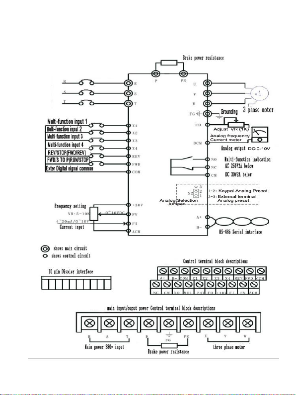
2.3 KD4000-2S(220V) basic wiring diagram....................................... 5
2.4 SD4000-4T (380V) basic wiring diagram...................................... 6
2.5 Control circuit wiring........................................................................7
2.6 Safety Considerations.....................................................................8
Chapter 3 Operation Panel............................................................................ 10
3.1 Operation panel description( digital keypad is optional).......10
I. Digital Keypad Operation........................................................10
II. Digital Keypad Parts and Functions....................................11
III. Explanation of the display.................................................... 12
3.2 Digital Keypad Operating Modes & Programming steps......13
3.3 Please observe below steps to set parameters......................14
3.4 Basic Wiring Diagram................................................................... 15
3.5 Troubleshooting and Fault Information.....................................32
Chapter 4 Quality and Guarantee................................................................ 34

Chapter 1 Production Overview
2
Chapter 1 Production Overview
1.1 Precautions on commodity inspection and storage
Before delivery, all goods are under strictly quality control and well
packed. However it may damage during the international transportation,
please check them carefully:
1. Check the package condition to make sure no damage happened
during transportation
2. Open the package and find out the user manual
3. Check the nameplate information on side of the inverter, be sure you
get the right product or spare parts
For any problem you may have, please contact your supplier!
STORAGE
Inverter should be packed and stored in ventilate and dry place. Keep
it away from corrosive gas, liquid and stained conditions.
The relative Humidity suggest to be 0% - 95% , no condensing,
The allowed temperature range is from -25℃to 65℃
Transportation Cautions:
Temperature range is from -25℃to 70℃
Relative Humidity is allowed to be 5% - 95%
Atmospheric pressure is allowed to be from 70kpa to 106kpa.

Chapter 2 Installation and wiring
3
Chapter 2 Installation and wiring
2.1 KD4000-2S(220V) Series Installation Dimension

Chapter 2 Installation and wiring
4
2.2 KD4000-4T(380V) Series Installation Dimension

Chapter 2 Installation and wiring
5
2.3 KD4000-2S(220V) basic wiring diagram

Chapter 2 Installation and wiring
6
2.4 SD4000-4T (380V) basic wiring diagram

Chapter 2 Installation and wiring
7
2.5 Control circuit wiring
The Control circuit wiring should be separated from the main circuit
wiring. Do not put them together in one slot.
Terminal marks:
Terminal
marks
Terminal Function
Supplement
COM
External multifunctional common
terminal
X1-COM
The first input terminal
4 terminals can build up
16 speeds. 0000 refers
first speed,0001 refers to
second speed,0010
refers to third speed ,
0011 refers to fourth
speed…..1111 is the 16th
speed
X2-COM
The second input terminal
X3-COM
The third input terminal
X4-COM
The fourth input terminal
FWD-CO
M
Forward rotation/ Stop
Run ->Stop
Stop ->forward rotate
REV-COM
Reversion/ Stop
Run->pause
Stop ->reverse
DCM
Digital signal
FO-DCM
Analog Cymometer /
galvanometer
ACM
Analog signal
CM
The common point of output
instruction signal
contact output of the
relay
contact output of the
relay

Chapter 2 Installation and wiring
8
NO-CM
The open point of output
instruction signal
NC-CM
The closed point of output
instruction signal
FI-ACM
Input terminal of analog
current
4~20mA
FV-ACM
Input terminal of analog voltage
0~+10V / Maximum
output frequency
10V-ACM
Power for setting speed
+10V Speed instruction
power
A+
Communication terminal A
RS485
B+
Communication terminal B
§The control signal wire is shielded and stranded
§ Wire for RS-485 communication should be the twisted pair
2.6 Safety Considerations
1. Please use right wires according to relative laws. When the distance
between inverter and motor is over than 25meters, should raise wiring
standard.
2. Between the three-phase AC input power and main circuit terminal
(R,S,T) there must be a fuse switch. Make an electromagnetic contactor
in series to cut off power before the inverter steer its protection.
3. Ground terminal to the first grounded wiring.
The ground impedance must be less than 100R. Or make the ground
wire dimension is same with the main circuit wires.

Chapter 2 Installation and wiring
9
4.The inverter should not joint ground with other high current loads, must
be separated.
5.The ground wire should be shorter.
6.When the inverters are common ground, don’t make a ground loops.
7.Confirm the voltage and maximum current.
8. The power indicator on the side of inverter shows the voltage inside
the inverter.
9.When the power indicator is lighting ,do not connect or disassemble
wires.
10. The SD4000 series is not equipped with the brake resistor. In the
occasion of frequently starting or stopping inverters, please install brake
resistor or unit.
11.Please connect the inverter’s terminal U,V,W with motors’
correspondingly. If the FWD lights, means the inverter is forward rotation;
if the REV lights, means the inverter is reversing. When the inverter is
forward rotation and motor is reversing,swap any two terminals of the
motor.
Do not connect the AC power with output terminals of the inverter.

Chapter 3 Operation Panel
10
Chapter 3 Operation Panel
3.1 Operation panel description( digital keypad is optional)
I. Digital Keypad Operation
This digital keypad module includes two parts: display panel and keypad.
The display panel allows the user to program the AC drive, as well as
view the different operating parameters. The keypad is the interface for
user and inverter.
. The following description refers to different parts.
LED indication
Red lamp lights during RUN,
STOP, JOG, FWD, or
REV operation.
LED display
Indicates frequency, motor
current
and alarm contents.
Forward / Reverse key
Selects FWD or REV
operation.
Jog key
While pressing this key, jog
speed is available.
Run key
Starts operation.
Program / Reset key
Selects normal mode or
program mode. Displays
the inverter status
Function / Data key
Displays the motor
drive status, or sets
parameters under the
requirement
Stop key
Stops operation.
Up and down keys
Sets parameter or
changes data

Chapter 3 Operation Panel
11
II. Digital Keypad Parts and Functions
KEY
Functions
For normal operating or programming mode (the key is
always valid)
. Must select programming mode to modify parameters
If the drive is shut down due to a fault occurs, after
troubleshooting, press this button will clear the error
message.
This is data setting key. In normal operating mode, press
this button to display the drive status information, such as
frequency command, output frequency and input current;
in programming mode, press this key to display the
parameter content. Then Press this button again will save
the changed parameters to the internal memory
Select forward or reverse operation. Press this button , the
motor will decelerate to 0HZ and change direction, but
motor will not restart automatically after the shutdown. An
external terminal can control motor forwarding or
reversing, when modify Pr.001 to "d0001" or "d0002"
Press this button ,the motor will run at jog frequency as set
by the parameter specified under Pr.23
start running key (if set to an external terminal control,
press this key is invalid)
Stop key.
Press the “Up” and “Down” button to select or modify
parameters ..
Note: Pressing the “Up” or “Down” button momentarily
changes the parameter settings in increments. Press and
hold these keys to rapidly run through the possible
settings.

Chapter 3 Operation Panel
12
III. Explanation of the display
Display
illustration
Display the operating frequency of inverter .The
frequency instruction may from self frequency setting or
from jog frequency or multifunctional terminal 1,2,3,4. If
frequency originates from digital keypad, user can use
UP DOWN KEY to set it and saved automatically
Display the operating frequency output to motor
Display the operating AC voltage input to inverter
Display the output current of inverter
Display the specified parameter code. The present
parameter
Value will be displayed by pressing the key.
Display present parameters.
Press the key to store the modified parameters.
The parameter is accepted and stored automatically at
internal memory when the “end” (as left picture)
remains approximately 1 second on the display.
LED indicators
RUN: light up means working
STOP: red light means stop working
JOG red light means operating jog command
FWD red light means forward operation
REV red light means reversal operation
Digital keypad instructions:
The keypad will display below information after power on. Press ‘RUN’ ,
inverter will work at 50.00hz as default ; Press ‘stop’ inverter will stop
working. Abide following steps to set frequency data.

Chapter 3 Operation Panel
13
3.2 Digital Keypad Operating Modes & Programming steps
NOTES: :Display changes every time or key is pressed.

Chapter 3 Operation Panel
14
3.3 Please observe below steps to set parameters

Chapter 3 Operation Panel
15
3.4 Basic Wiring Diagram
Summary of Parameter Settings
Code
Parameter
Function
Explanation
Parameter Value
Factory
Setting
Pr.000
Main
frequency
source
selection
setting
Select the
main (first
paragraph)
frequency
source
d0000:Main frequency (first
paragraph) is determined
by the digital keypad, press
the up and down arrow
keys to modify
d0000
d0001: Main frequency
(first paragraph) is decided
by the input analog signal
(DC 0 ~ +10 V) + (DC 4 ~
20mA); Please set the
parameters Pr.28 , Pr29,
Pr41, Pr.42 correctly
d0002:Main frequency (first
paragraph) is decided by
RS-485 communication
interface
Pr.001
source of run
command
selection of
running
signal source
d0000: Run command is
determined by digital
operator
d0000
d0001: Run command is
determined by external
terminals .STOP key is
valid
d0002: Run command is
determined by external
terminal decision, STOP
key is invalid

Chapter 3 Operation Panel
16
Code
Parameter
Function
Explanation
Parameter Value
Factory
Setting
d0003:Run command is
determined by the RS-485
serial communication
interface, STOP key is valid
d0004: Run command is
determined by RS-485
serial communication
interface, STOP key is
invalid
Pr.002
selection of
stop mode
selection of
stop mode
d0000: RAMP stop
d0000
d0001: Coast to stop
Pr.003
V / F curve setting
Note: curve setting
conditions :
1. Max.operating
frequency >= Mid-point
frequency >= Min. output
frequency; 2. Max. output
voltage >= Mid-point
voltage >= Min. output voltage
(Note : Do not modify this
parameter when motor is
running)
Max. operating frequency
d010.0--d400.0 Hz
d050.0
Pr.004
Max. voltage frequency
d010.0--d400.0 Hz
d050.0
Pr.005
Max. output voltage
d010.0--d250.0 V/400.0v
d220.0
Pr.006
Mid-point frequency
d010.0--d120.0 Hz
d001.5
Pr.007
Mid-point voltage
d010.0--d250.0 V
d040.0
Pr.008
Min. output frequency
d010.0--d120.0 Hz
d001.0
Pr.009
Min. output voltage
d010.0--d250.0 V
d035.0
Pr.010
DC-BUS brake level
220V Series Brake Level
d0260-d320V
d0280
380V Series Brake Level
d0440--d550V
d0480

Chapter 3 Operation Panel
17
Code
Parameter
Function
Explanation
Parameter Value
Factory
Setting
Pr.011
Selection of acceleration and
deceleration for S
curve(Note : Do not modify
this parameter when motor is
running)
d0000: line Acc/Dec Mode
d0001: S curve Acc/Dec
Mode
d0000
Pr.012
Days of the accumulated
running time
d0000—d9999
d0000
Pr.013
Hours of the accumulated
running time
d0000—d0000
d0000
Pr.014
Jog acceleration and
deceleration time settings
d000.1—d600.0s
d015.0
Pr.015
settings of forward and
reversal frequency for JOG
d000.1—d120.0 Hz
d015.0
Pr.016
Prohibit
reversal
setting
Notes:
Inverter will
stop REV
function
without
reminding
when prohibit
reversal is
setup.
d0000:Allow Reversal
d0000
d0001: Prohibit reversal
Note: REV and FWD are
relative concept. Please
carefully check the motor
direction in the occasion of
reversing is not allowed.
Pr.017
setting for
over-voltage
stall
prevention
Over-voltage
stall
prevention
setting
d0000: Over-voltage stall
prevention function is
invalid
d0001
d0001: Over-voltage stall
prevention function is valid.
Pr.018
Setting for
over-current
during
accelerate
d0050—d0200%
d0140
Pr.019
Setting for
over-current
during running
d0050—d0200%
d0140

Chapter 3 Operation Panel
18
Code
Parameter
Function
Explanation
Parameter Value
Factory
Setting
Pr.020
Setting for
percentage of
DC braking
current
Please set
0% when
don’t need
DC current to
brake
d000.0—d050.0%
d008.0
Pr.021
Setting the
time for DC
current
braking on
start the motor
Set up to 0 to
shut down
this function
d000.0—d025.0s
d0000
Pr.022
Setting the
time for DC
current
braking on
stop the motor
Set up to
0.0s to shut
down this
function
d000.0—d120.0s
d001.5
Pr.023
Setting the
starting
frequency for
the DC
current
braking when
shut down
motor
Before
decelerating
to stop, this
parameter is
the starting
frequency for
DC current
brake. It will
work when
the
parameter is
smaller than
the min.
frequency(pr.
008)
d000.0—d060.0 Hz
d001.0
Pr.024
Momentary
power
loss protection
d0000: Operation stops after momentary
power
Loss.
d0000
d0001: Operation continues after
momentary
power loss. Track down with operating
frequency

Chapter 3 Operation Panel
19
Code
Parameter
Function
Explanation
Parameter Value
Factory
Setting
d0002: Operation continues after
momentary
power loss. Track up from minimum output
frequency.
d003: refer to Pr025
Pr.025
Setting for
restarting time
after
momentary
power loss
d000.3—d005.0 s
d000.2
Pr.026
Setting for the
Max. tracking
time when
power on
d000.3—d005.0 s
d000.5
Pr.027
Selection of
the max.
current for
speed
tracking
d0030 —d0200%
d0150
Pr.028
Selection of
the max.
input analogy
frequency
d000.0—d120.0 Hz (when Pr.000=1)
d050.0
Pr.029
Selection of
the min.
input analogy
frequency
d000.0—d120.0 Hz (when Pr.000=1)
d000.0
Pr.030
External
control
terminal
setting
(2-wire /
3-wire
operation
control
d0000:X5 FWD / STOP, X6 REV / STOP
d0000
d0001:X5 FWD / REV, X6 RUN / STOP
d0002: X4,X5,X6 is the 3-WIRE operation
control mode
This manual suits for next models
2
Table of contents
Other Karda Inverter manuals
Popular Inverter manuals by other brands

Chicago Electric
Chicago Electric 66835 Set up and operating instructions

Haier
Haier SUPER MATCH AS25S2SF1FA-BH Service manual

Jntech
Jntech JNP22KH-V5 user manual

Sensata
Sensata Dimensions 12LP15 owner's manual

Hyundai power products
Hyundai power products QL2000i instruction manual

Generac Power Systems
Generac Power Systems 00919-0 owner's manual