KARL KAPS SOM 62 LED User manual

SOM 62/32/22
LED
Instructions for use
Karl Kaps GmbH & Co KG
Schulstrasse 57
Tel. + 49 (0) 6441 / 80704-0
service@kaps-optik.de
35614 Asslar
Germany
Fax. + 49 (0) 6441 / 85 9 85
www.kaps-optik.de

Instructions for use SOM 62/32/22 LED
SOM 62/32/22 LED EN 2017-03
Contents
1General 1
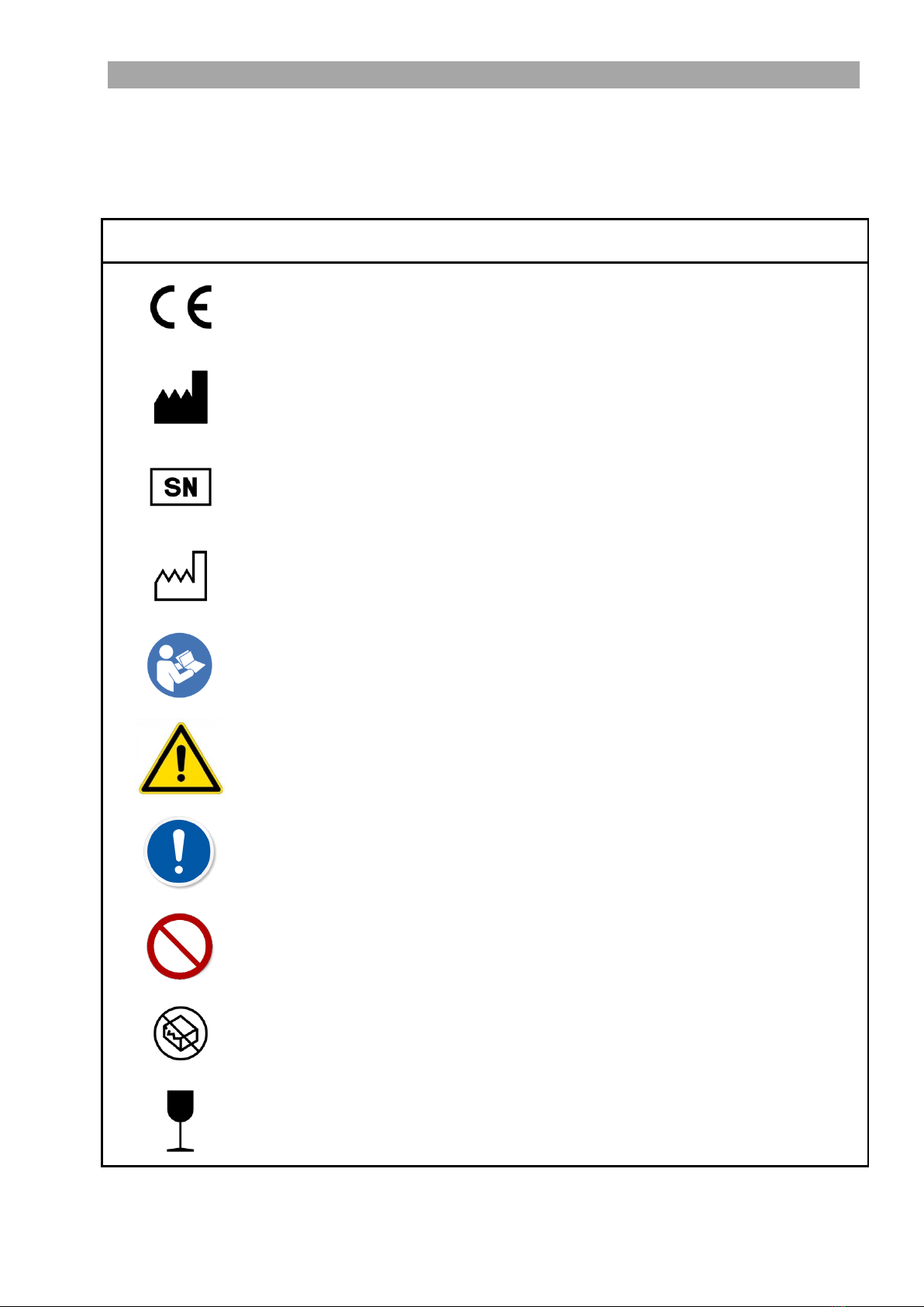
2Symbols used and what they mean 2
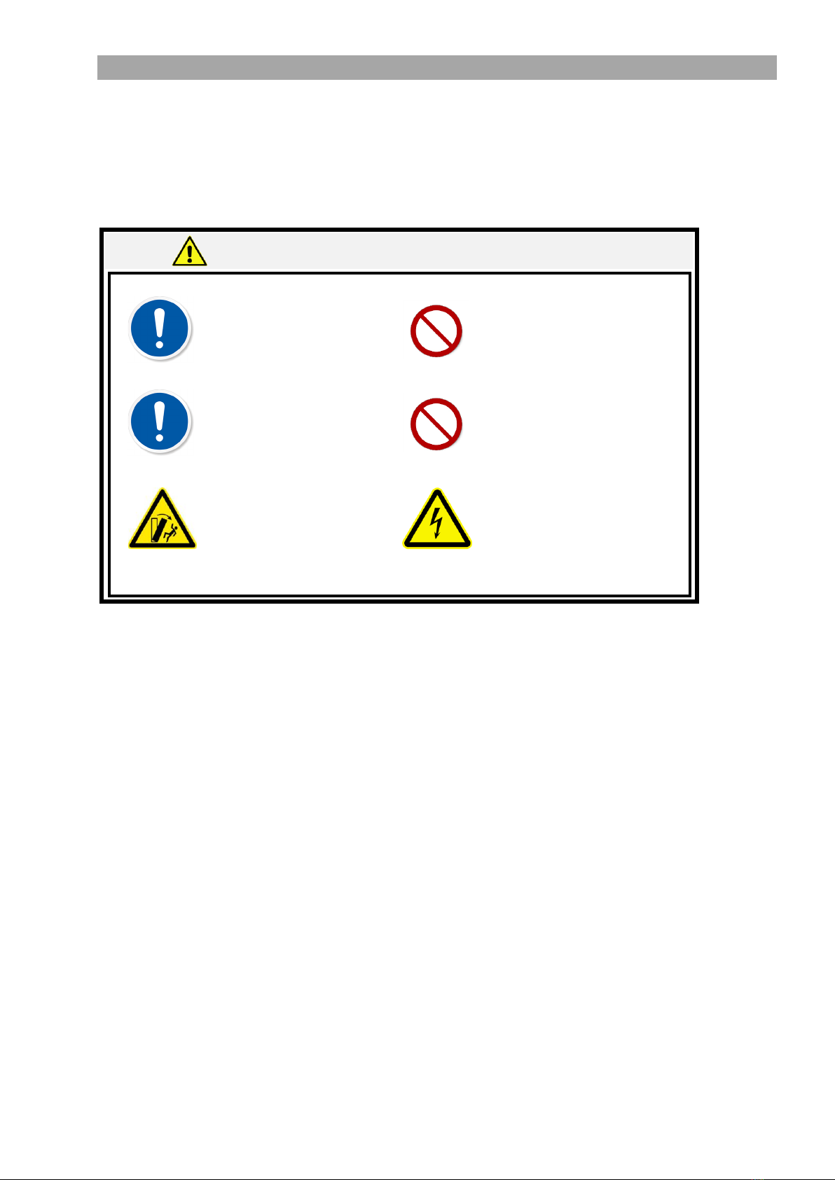
3Warning and safety advice 4
3.1 Installation instructions 4
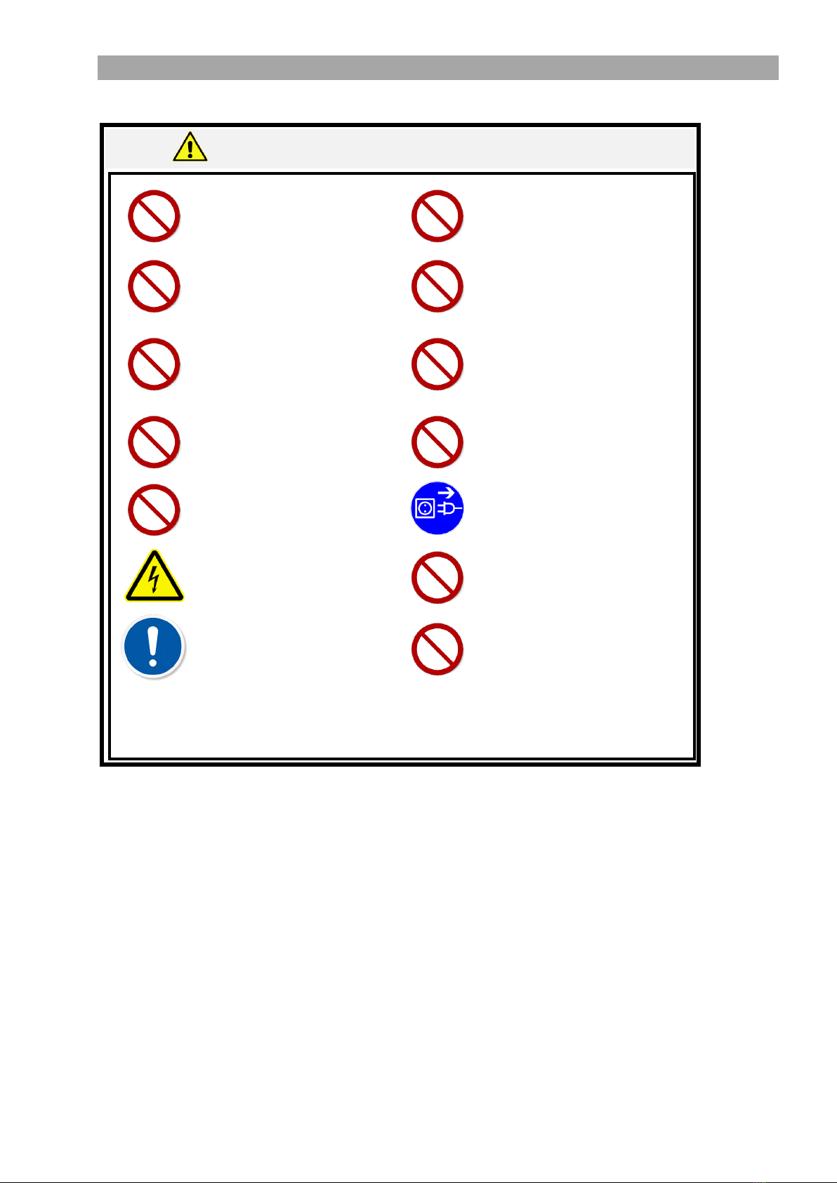
3.2 Notes for use and disposal 5
4Directives, laws and standards 6
5Delivery state 6
5.1 Deliverables 6
5.1.1 Deliverables for SOM 62 LED 6
5.1.2 Deliverables for SOM 32 LED 6
5.1.3 Deliverables for SOM 22 LED 7
5.2 Transportation/packaging/unpacking/checking 7
5.2.1 Unpacking 7
6Intended use 7
7Installation 8
7.1 Installation of SOM62 8
7.1.1 Installation of wheeled stand and column 8
7.1.2 Installation of swivel arm, suspension arm and microscope 9
7.2 Installation of SOM 32 10
7.2.1 Installation of the ceiling bracket 10
7.2.2 Installation of swivel arm, suspension arm and microscope 11
7.2.3 Connecting up to the voltage supply 12
7.3 Installation of SOM 22 13
7.3.1 Fitting of the wall bracket 13
7.3.2 Installation of swivel arm, suspension arm and microscope 14
8Device description 14
8.1 Identification and nameplates 14
8.2 Controls 15
8.2.1 Controls 15
8.3 Medical performance data 16
8.4 Additional loads 16
8.5 Suspension arm adjustments 16
9Preparation 17
9.1 Power supply 17
9.2 Brakes 17
9.3 Adjusting eye distance 17
9.4 Focusing 18
9.5 Checklist 18
10 Operation 19
10.1 Transport position / rest position (SOM62 LED only) 19
10.2 Replacing objective and eyepieces 20
10.3 Switching the device on and off 21
10.4 Brightness control 22
10.5 Magnification adjustment 23
10.5.1 Magnification setting on the changer 23
10.5.2 Magnification setting on the zoom unit 23
10.6 Swivelling in/out the filter 24

Instructions for use SOM 62/32/22 LED
SOM 62/32/22 LED DE 2017-03
10.7 Removing/exchanging the binocular tube 24
11 Shutting the system down 25
12 Cleaning and maintenance 25
12.1 Fuse replacement 25
12.2 Disinfection and sterilisation 26
12.3 Cleaning optical surfaces 26
12.4 Cleaning painted parts 26
12.5 Maintenance 26
12.6 Replacing LEDs 26
12.7 Replacing the power lead 26
13 Disposal 26
14 Accessories 27
15 When faults occur 28
15.1 Summary of potential faults 28
16 Technical description 29
16.1 Technical details 29
16.2 Dimensions 30
16.2.1 SOM 62 LED 30
16.2.2 SOM 32 LED 31
16.2.3 SOM 22 LED 31
17 Declaration of conformity 32
18 Warranties 33

Instructions for use SOM 62/32/22 LED
1 SOM 62/32/22 LED EN 2017-03
1General
Thank you for selecting one of our quality products. Kaps devices combine excellent illumination,
easy and exact positioning, and very good optical performance in a variable and modular system.
Your product can be subsequently aligned to different requirements at any time without problem.
The ergonomic design of our products enables users to work without becoming tired. A brilliant 3-
dimensional image with high depth of focus enables best possible success quotas in your
diagnostics.
This instruction manual is an integral part of the deliverables and is part of the medical product. It
must be kept in an easily accessible place by the operator for all users, and remains part of the
product even when the product is sold on.
We reserve the express right to make changes to specifications shown in this instruction manual
that result from technical enhancements.
Reprints, translations and duplications in any form, in whole or in part, require consent in writing
from the publisher. Copyright lies with the publisher.
This instruction manual is not subjected to change management. Please contact the product
manufacturer for the current revision.

Instructions for use SOM 62/32/22 LED
SOM 62/32/22 LED EN 2017-03 2
2Symbols used and what they mean
Important visual instructions are on the device packaging, in the instruction manual and on the device. The
symbols used have the following meanings:
Symbol
Explanation
By affixing the CE mark, the manufacturer certifies conformance of the
medical device to the fundamental requirements (Article 3) laid down in
Directive 93/42/EEC for medical devices
Shows the manufacturer of the medical device to EU Directive 93/42/EEC
Shows the serial number of a device so that a particular medical device can be
identified
Shows the date on which the medical device was manufactured
Follow the instruction manual. Failure to follow the instruction manual can
result in injury or material damage.
Caution
The warning triangle makes reference to potential sources of danger for people, to
injury risks or to health risks
General instruction sign. Denotes mandatory action by the user.
General prohibition sign. Denotes prohibited action by the user.
Shows a medical device that should not be used if the packaging is damaged
or open
Denotes a medical device that can break or be damaged if not handled with
due care

Instructions for use SOM 62/32/22 LED
3 SOM 62/32/22 LED EN 2017-03
Symbol
Explanation
Denotes the upper and lower temperature values to which the medical device
can be exposed safely
Denotes the moisture range to which the medical device can be exposed
safely
Denotes a medical device that must be protected from moisture
Denotes the necessity for the user to refer to the instruction manual for
important information pertaining to safety (such as warning signs and
precautionary measures) that cannot be affixed to the medical device itself
for a number of reasons
The product entered into circulation after 13 August 2005 and may only be
disposed of in a separated waste stream (i.e. not in household waste)
Specifies a handling instruction, failure to comply with which does not
result in injury or material damage
CAUTION
Denotes a danger that can cause minor injury or material damage
WARNING
Denotes a danger that can cause semi-serious injury or material
damage

Instructions for use SOM 62/32/22 LED
SOM 62/32/22 LED EN 2017-03 4
3Warning and safety advice
Follow the instructions in this operating manual for proper function and safety of the device.
Do not use the device when faults occur.
3.1 Installation instructions
WARNING
The mains plug of the device is used
to isolate the device from the mains
power supply. Set up the device
such that the mains plug can be
accessed without obstruction at all
times.
The ventilation for the device may not
be obstructed.
Caution. To prevent the risk of
electrical shock, this device may
only be connected to a supply
having a protective earth
connector.
To prevent damaging the device, do
not drop it or parts of it, or expose
it/them to other mechanical forces.
Only use approved components.
Unapproved components can have
a bearing on the load-carrying
capacity and stability of the device,
and can cause damage to the
device.
If the power lead is defective,
immediately disconnect the device
from the mains supply and contact
the manufacturer.

Instructions for use SOM 62/32/22 LED
5 SOM 62/32/22 LED EN 2017-03
3.2 Notes for use and disposal
The residual risk of a hazard is assessed as extremely low if all instructions are followed and the
device is used as intended.
WARNING
The microscope may only be
deployed for its intended use (as
specified in these instructions).
Whilst the device is being used,
ensure the patient does not look into
the illumination unit of the
microscope.
Maintenance and repairs may only be
carried out when required by
authorised specialists or by factory
customer service.
Penetration of liquids into system
components must be reliably
prevented.
Only spare parts and accessory
components approved by the
manufacturer may be used. Please
contact the manufacturer in the
event of doubt.
When a fault occurs (such as when a
fan is defective or ventilation slits are
covered), immediately switch off the
device so as not to cause any damage
to it.
Only replace defective fuses with
those having the same ratings
(nominal voltage, nominal current
and switch-off characteristics).
Whilst the device is in use, all fuse
components must be correctly
inserted as described in this manual.
Use of the microscope is only
permitted in dry rooms.
Unplug the mains connector before
changing fuses.
Ensure that the device is only run on
voltages specified on the nameplate.
Do not use the device near sources of
electromagnetic radiation.
The device is fitted with a high-
performance light source. Ensure that
neither user nor patient is blinded by
the light.
Modifications to the device are strictly
forbidden without consent from the
manufacturer.

Instructions for use SOM 62/32/22 LED
SOM 62/32/22 LED EN 2017-03 6
4Directives, laws and standards
The medical device described here conforms to the fundamental requirements laid down in
Directive 93/42/EEC for medical devices. A conformity assessment procedure to Appendix VII has
been conducted successfully. The following harmonised standards were applied for the conformity
assessment procedure:
EN 60601-1:2005 (ed.3)
EN 60601-1-2:2007 (ed.3)
EN 60601-1-6:2007
EN ISO 14971:2009-10
EN ISO 13485:2010-01
DIN EN 980: 2008-08
ISO 11884-1-2006
EN ISO 9001:2008
DIN EN 62471:2009-03
Directive 93/42/EEC
5Delivery state
5.1 Deliverables
The product is delivered as described below (depending on device model).
5.1.1 Deliverables for SOM 62 LED
The device is delivered as four individual sub-assemblies:
Wheeled stand with four rollers
Column
Swivel and floating arms with electrical supply and lighting
Microscope head including attachment
Instruction manual
Fasteners for all components are included.
5.1.2 Deliverables for SOM 32 LED
The device is delivered as three individual sub-assemblies:
Ceiling bracket
Swivel and floating arms with electrical supply and lighting
Microscope head including attachment
Operating instructions
Fasteners for all components are included.

Instructions for use SOM 62/32/22 LED
7 SOM 62/32/22 LED EN 2017-03
5.1.3 Deliverables for SOM 22 LED
The device is delivered as three individual sub-assemblies:
Wall bracket
Swivel and floating arms with electrical supply and lighting
Microscope head including attachment
Operating instructions
Fasteners for all components are included.
5.2 Transportation/packaging/unpacking/checking
The device is delivered as separate assemblies as described above, and installed and tested for
correct function by the specialist retailer or support personnel.
Check the packaging for damage before unpacking the device. If the packaging is
damaged, the contents may be as well. If the packaging is visibly damaged, please notify
the carrier immediately.
5.2.1 Unpacking
All packaging and filler material must be disposed of in line with applicable local regulations.
After unpacking all of the components, use the delivery note to check the delivery is
complete. If it is not, notify the supplier immediately.
6Intended use
The product is intended for general-purpose operative and diagnostic medical deployment. It is
used for optimum illumination and magnification of the treatment area. The product may only be
used by trained specialists for the medical application described in this instruction manual.
Training is held by the manufacturer or by personnel authorised by the manufacturer. Intended
use does not include contact with the patient. The device may only be used in interior rooms
having sufficient levels of illumination and cleanliness.

Instructions for use SOM 62/32/22 LED
SOM 62/32/22 LED EN 2017-03 8
7Installation
The device may only be installed by personnel assigned by the manufacturer, or by the
manufacturer itself. Only the fixing and installation materials supplied may be used.
7.1 Installation of SOM62
7.1.1 Installation of wheeled stand and column
Carry out the following installation steps as in Figure 1:
The four rollers (2) are already screwed to the foot (1). The rollers are fitted with brakes.
Engage/disengage the brakes on the rollers when moving and securing the device.
Place the column (3) onto the flange of the foot and tighten it with four screws (5), using the
tool provided
Hang the eight lead weights (6) into the bars of the foot
Put on the protective cover (4)
Secure the cover using the clamp ring (8) and four screws (7). Use the tool provided.
CAUTION
Be careful with the lead weights. Ensure not to drop them and protect
hands, etc. from falling weights.
Figure 1

Instructions for use SOM 62/32/22 LED
9 SOM 62/32/22 LED EN 2017-03
7.1.2 Installation of swivel arm, suspension arm and microscope
Carry out the following installation steps as in Figure 2:
Undo the lock screw (3) on the upright guide cylinder (1) of the column (2)
Put on the swivel arm (5). Ensure in the process that the star knob (4) is undone.
Screw the lock screw (3) back on
Undo the safety cap (6) from the guide cylinder (7) of the microscope carrier (8)
Press in the lock pin (10) and push in all the way the guide cylinder of the microscope carrier.
The star knob (9) must be undone for this. Release the lock pin - it engages into place and
prevents the microscope head (11) from falling out.
Hand-tighten the lock cap (6) onto the projecting threaded part of the guide cylinder
CAUTION
Always ensure that the lock screw (3) for securing the swivel arm, and
the lock screw (6) for securing the microscope head, are mounted
correctly.
Figure 2

Instructions for use SOM 62/32/22 LED
SOM 62/32/22 LED EN 2017-03 10
7.2 Installation of SOM 32
7.2.1 Installation of the ceiling bracket
Carry out the following installation steps as in Figure 3:
Using the aligner (1), drill four holes into the ceiling (Ø 10mm, hole depth 80mm)
Clean the holes and check the distance between the holes using the aligner (1)
Hammer in four through anchors (2) up to the mark and secure them to the torque specified
(45 Nm)
Secure the aligner (1) to the ceiling using four screws (3) and four nuts (4)
Before fitting the ceiling column to the aligner, place the mains cable (15) (on the connector
side) into the groove and ensure the mains cable is not pinched
Unscrew the socket plate (6) from the column. Pull the cable down by about 150mm.
Screw four threaded bolts (7) into the aligner (1) and secure them with lock ring (8) and nut
(9). Screw another four nuts (9) onto the threaded bolts (7). Put the washers (11) onto the
threaded bolts.
Insert the column with flange (10) into the four threaded bolts (7) of the aligner, and secure
with four lock rings (8), four washers (11) and four nuts (9). Then align the column to be
perfectly vertical.
Put on the cover (12), guide the mains plug out of the ceiling bracket and attach it with ring
(13) and three threaded pins (14)
Carefully guide the cable (15) into the column, and insert and tighten the socket plate (6)
Figure 3

Instructions for use SOM 62/32/22 LED
11 SOM 62/32/22 LED EN 2017-03
7.2.2 Installation of swivel arm, suspension arm and microscope
Carry out the following installation steps as in Figure 4:
Undo the lock screw (2) on the upright guide cylinder (4) of the column (6)
Put on the swivel arm (1). Ensure in the process that the star knob (5) is undone.
Re-tighten the lock screw (2)
Screw the threaded pin (3) all the way into the threaded hole of the lock screw, and
tighten it
Carry out the remaining steps as in 7.1.2
Figure 4
WARNING
Ensure at all times that the lock screw (2) is screwed in all the way
and that the threaded pin (3) is tightened. It must not be possible
for the lock screw (2) to become loose. Only the fixing and
installation materials supplied may be used.

Instructions for use SOM 62/32/22 LED
SOM 62/32/22 LED EN 2017-03 12
7.2.3 Connecting up to the voltage supply
Plug the connector (1) into the socket (5), noting the orientation of the connector
Tighten the sleeve ring (2)
Ensure that the spiral cable (4) does not turn excessively when the swivel arm (3) is rotated
Figure 5

Instructions for use SOM 62/32/22 LED
13 SOM 62/32/22 LED EN 2017-03
7.3 Installation of SOM 22
7.3.1 Fitting of the wall bracket
Carry out the following installation steps as in Figure 6:
Use the drill template (1) to drill four holes into the relevant wall.
The lower edge of the drill template must be about 1.65m above the floor.
Remove the drill template
Insert metal wall plugs (2). The front edges of the metal wall plugs must be flush with the
wall surface.
If the drill bit deviates, drill the holes to be bigger and cement in the metal plugs (2). Check
the plug distances with the drill template (1).
Allow the cement to harden.
Align the wall bracket (3) before securing it, and then secure it using four screws (4) and four
washers (5). Tighten the screws.
Figure 6
WARNING
Only affix the device to walls capable of bearing the weight. Only
the fixing and installation materials supplied may be used.

Instructions for use SOM 62/32/22 LED
SOM 62/32/22 LED EN 2017-03 14
7.3.2 Installation of swivel arm, suspension arm and microscope
Proceed with the steps in Section 7.1.2
8Device description
8.1 Identification and nameplates
The nameplate is used for accurate identification of your product. It may not be removed or
modified. Figure 8 shows the position of the nameplate. It is located on the flat side of the swivel
arm (1), regardless of device variant.
Figure 7
Figure 8

Instructions for use SOM 62/32/22 LED
15 SOM 62/32/22 LED EN 2017-03
8.2 Controls
8.2.1 Controls
The device (SOM 62 only) is positioned on the floor with the wheeled stand. The foot has four
rollers for moving the device. The following locking mechanisms, securing elements and controls
are also fitted on the device (the same applies for SOM 22/32).
Star knob (1) for determining the swivel arm position
Main switch (14)
Potentiometer (10) for regulation of lighting
Star knob (3) for determining the height movement for the suspension arm
Star knob (5) for rotation protection of the microscope head
Knurled screw (8) for exchanging the binocular lens tube
Knob (12) for adjusting the magnification changer
Locking pin (4) to protect the microscope head from falling out during installation
Star knob (2) for determining the rotation movement for the suspension arm
Nameplate (13)
Clamp lever (9) for adjusting the required friction to tilt the microscope head
Lever (15) for swivelling in/out the colour filter (if available)
Figure 9
The nameplate (13) must be legible at all times. If the nameplate is not legible, or is
missing, a replacement must be sought.

Instructions for use SOM 62/32/22 LED
SOM 62/32/22 LED EN 2017-03 16
8.3 Medical performance data
The medical performance data pertains to the required medical performance data of the medical
device. This performance data is listed in Section 16 "Technical description".
8.4 Additional loads
The load capacity and tipping stability of the systems are aligned to the components in our
product range. Only approved components may be installed and used.
8.5 Suspension arm adjustments
The weight adjustment of the suspension arm is set at the factory to the requirement on delivery.
The suspension arm adjustment may have to be aligned when components are used on or
removed from the device head. (Anti)clockwise adjustment of the Allen screw (1) is used for this.
Figure 10

Instructions for use SOM 62/32/22 LED
17 SOM 62/32/22 LED EN 2017-03
9Preparation
9.1 Power supply
Use the power lead to connect the device to the local voltage supply.
9.2 Brakes
The clamps are adjusted by tightening/loosening the star-knob screws (see Section 8.2). The
device clamps must be adjusted so that the degree of free movement satisfies the respective
requirements.
CAUTION
Never fasten the brake of the suspension arm (3 in Fig. 9) when the
suspension arm has no load.
Never move the suspension arm when its brakes are activated.
9.3 Adjusting eye distance
The eye distance must be set individually for every user.
To do this, move the microscope to the working position and view an object through the
eyepieces. The eyepieces must be set to Index 0. The object must now be brought into focus by
adjusting the working distance. The distance of the eyepieces is now set in line with the lens tube
used by turning the knob (1). It must be possible for both eyes to make out the object by the same
amount, i.e. the object should be seen as a single 3-dimensional image.
Figure 11
This manual suits for next models
2
Table of contents
Other KARL KAPS Medical Equipment manuals