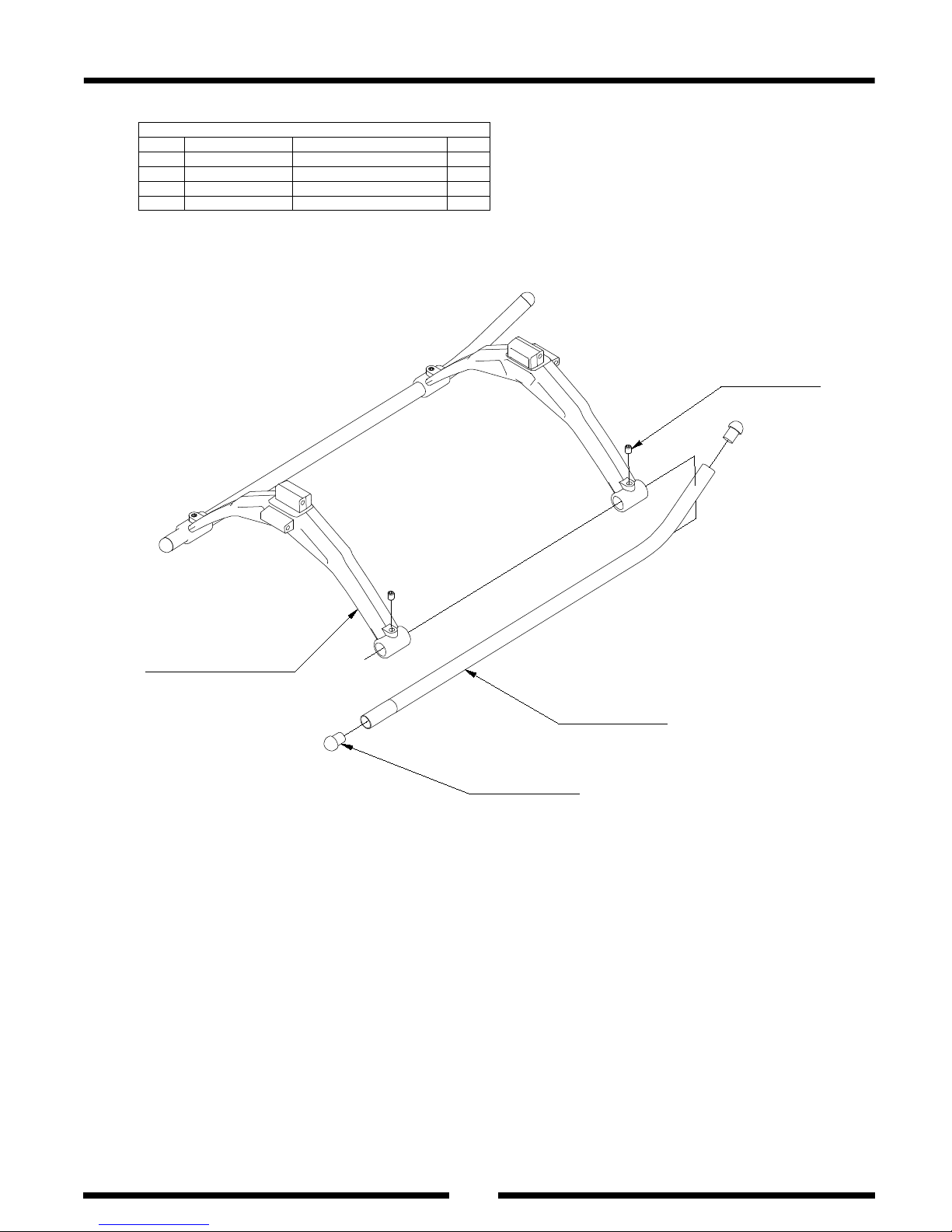
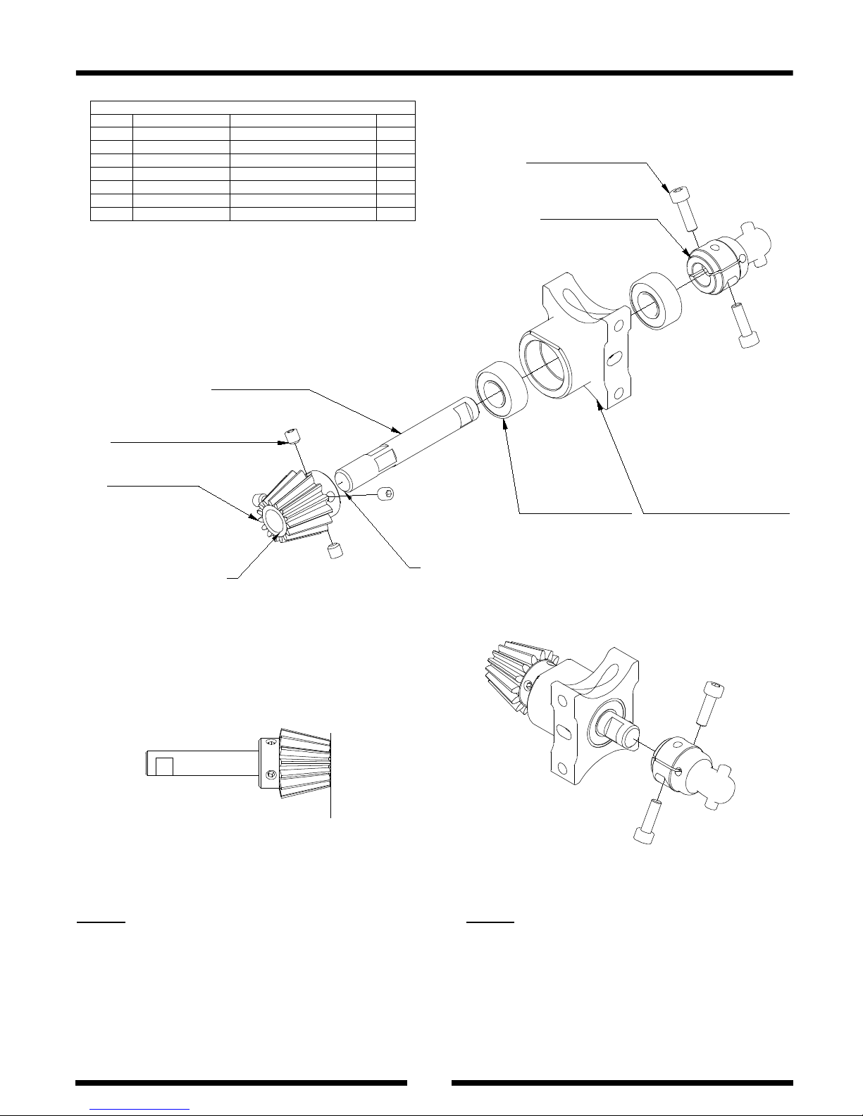
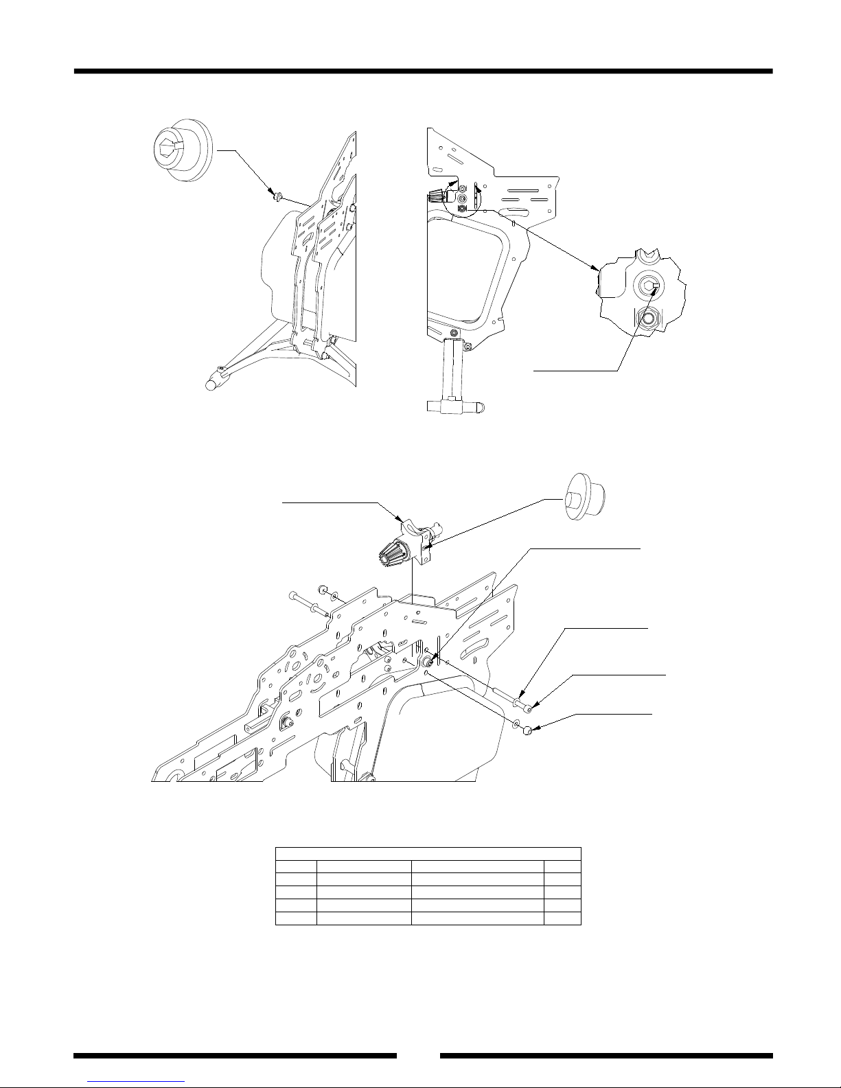
Note: Apply blue thread lock to all screws, balls, and threads which it be
fixed to metal-parts. For non-metal parts apply CA Glue.
Thank you for your purchase of Srimok 90 radio controlled helicopter .
The Srimok 90 was designed and developed by Mr. Kasama Thaworn. With
strong and friendly support from Ultimate heli U.A.E. It combines both
elements of his previous designs , newly advanced technologies and
materials . The design ideas are not only from flying , but also from
many years of rc experience . So the beginners and advanced 3-d fliers
will definitely be impressed with Srimok 90.
This radio controlled helicopter is not a toy. It is a sophisticated piece
of equipment that was designed for hobby use only .If it is not properly
assembled , maintained or operated , it is capable of causing property
damage and bodily harm to both operator and/or spectators . Kasama
helicopters co., ltd. affiliates and its authorized affiliatesassume no
liability for damage that could occur from the assembly, use and/ misuse
of this product. If you are new to the hobby we strongly recommend
seeking help and advice from an experienced modeler. Srimok90 is a very
high speed helicopter, it was
not intended for beginners or novice
building, setup or flying.
Operatiing a model helicopter requires a high degree of diligence and
skill. if you are a newcomer to the hobby , it is best to seek help and
guidance from experienced radio controlled helicopter pilots . This will
both greatly speed up the learning process and make it much safer and
enjoyable.
We also would strongly urge you to join the Academy of Model
Aeronautics. The AMA is a non-
profit organization that provides its
member with a liability
insurance plan as well as monthly magazine
entitled Model aviation .All clubs operate in accordance with AMA
principles at their fields. For further information ,contact the AMA at
Academy of Model Aeronautics
5151 East Memorial Drive
Muncie, in47302
[317] 287-1256
INTRODUCTION