Kasco 3400EVFX User manual

Owners Manual
50Hz Fountains
2400EVFX, 3400EVFX, 4400EVFX
2400EJF, 3400EJF, 4400EJF
Contents
Important Safety Instructions . . . . . .pg2
Unit Specs . . . . . .pg2
Quick Disconnect Installation . . . . . .pg2
Wire Sizing & Gland Sizing . . . . . .pg4
2400EVX, 2400EJ, 3400EVX, 4400EVX Parts . . . . . .pg4
EVFX Pattern Size Chart . . . . . .pg5
2400EVX, 2400EJ, 3400EVX, 4400EVX Assembly Instructions . . . . . .pg5
3400EJF, 4400EJF Parts . . . . . .pg6
3400EJF, 4400EJF Assembly . . . . . .pg7
2400EJF, 3400EJF, 4400EJF Nozzle Options . . . . . .pg8
Installation Instructions . . . . . .pg10
Maintenance Recommendations . . . . . .pg11
Troubleshooting Tips . . . . . .pg11
Rev. 02/18/09
Kasco Marine, Inc.
800 Deere Rd.
Prescott, WI 54021
U.S.A.
PH 00+1+715+262+4488
FAX 00+1+715+262+4487
www.kascomarine.com
Making a Splash!

2
CAUTION
NOTICE (NOTE)
These international safety symbols are used
throughout this manual to inform the owner of
important safety information and notices for
safe and effective use of the equipment.
Important Safety Instructions
CAUTION
Under NO circumstances should anyone enter• the water with the electrical equipment con-
nected and/or in operation. It is NEVER rec-
ommended to enter the water with the equip-
ment in operation.
Caution should be used when dealing with any• electrical equipment with moving parts.
NEVER run the unit out of water. It will dam-• age the seals and create a dangerous situation
for the operator.
Extreme caution should be used around water,• especially cold water, such as in Spring, Fall,
and Winter, which poses a hazard in and of
itself.
NEVER lift or drag the unit by the power or• light cord. If you need to pull the unit to the
side of the pond, use the anchoring ropes.
Do not use waders in deep ponds/lakes or• ponds/lakes with drop-offs, drastic slopes, or
soft bottom material.
Do not use boats that tip easily for fountain• installation, such as a canoe, and follow all
boating safety rules and regulations, including
wearing a PFD. (Personal Flotation Device)
The unit is supplied with an internal ground-• ing conductor. To reduce the risk of electrical
shock, be certain that the unit is plugged/con-
nected to an approved RCD (GFCI) protected
circuit.
Means for disconnection must be incorporated• in the fixed wiring in accordance with local and
national wiring rules.
Consult a qualified electrician for electrical• installation.
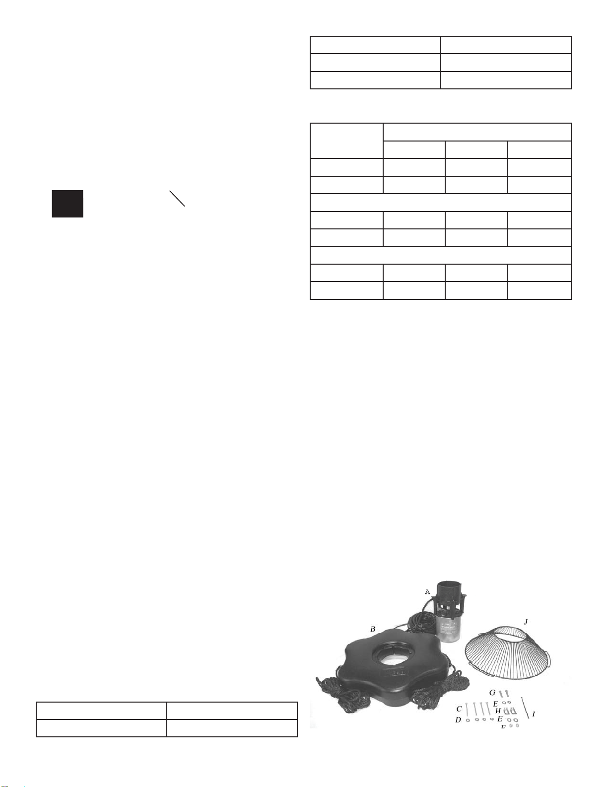
Unit Specs
Model Voltage Operating
amps lock rotor
amps
2400EVFX 208-240 2.2@240V 6@240V
3400EVFX 208-240 3.6@240V 9@240V
4400EVFX 208-240 5.9@240V 20@240V
2400EJF 208-240 2.2@240V 6@240V
3400EJF 208-240 3.8@240V 9@240V
4400EJF 208-240 6.5@240V 20@240V
Quick Disconnect Installation
Important – Read Carefully Before Installation
Before using the connector, it is important that these
instructions are carefully read and understood to
ensure the connector system is completely water tight
and electrically safe.
IF IN DOUBT CONSULTA QUALIFIED ELECTRI-
CIAN.
The socket (female) insert of the connector must be
the live part of the connector from the supply. The pin
(male) insert of the connector must lead to the load or
electrical device. On 50Hz units, the pin (male) insert
of the connector is installed at the factory. To ensure
efficient sealing, use only smooth circular cable.
Pin Insert (Installed on Stub Cord)
Pin Insert Main Body Gland Gland Nut
Socket Insert (User Installed)
Socket insert Main Body Gland Gland Nut

3
Note:
White gland for 9-11mm O.D.
Yellow gland for 13-15mm O.D.
Assembly/Wiring Instructions
STEP ONE
Remove the socket insert from the housing of
the connector. There is a slot for a flat blade
screwdriver in the center of the insert.
Note: The inserts have a LEFT HAND
THREAD and should be turned clockwise to remove.
STEP TWO
Remove the gland nut and gland from the rear of the
housing and slide on to the cable. Make sure the gland
is orientated with the stepped edge facing the gland
nut (see picture). Stepped Edge
STEP THREE
Prepare the cable and strip wire ends as shown.
Wire Stripping
STEP FOUR
Insert the stripped wire ends into the terminals on the
back of the Pin/Socket insert and fully tighten the
wire retention screws. (Refer to figure for correct wire
orientation).
Figure 5:
Wire Connections
Brown wire to terminal L
Blue wire to terminal N
Green/Yellow wire to terminal E
After the wires have been connected securely, pull the
cable and insert back into the housing and tighten with
a screwdriver to ensure the insert is seated correctly.
Note: LEFT HAND THREAD, turn the insert counter
clockwise to tighten.
STEP FIVE
Prepare your supplied Resin Kit by removing the cap
from the resin tube and pushing the resin nozzle onto
the tube. Then twist the nozzle to lock in place.
Plunger Resin Tube Nozzle
Before applying to the quick disconnect, use the
plunger to evenly push out a small amount of resin to
get a proper mix of of the 2-part epoxy. Then apply
resin into the housing, enough to cover the wires and
contacts. The resin should be about 3mm onto the
cord jacket. Note: Adding too much resin may cause
excess to be forced into the female end of the pin
connector, preventing proper connection of the two
halves.
Cut-Away
disconnect shown
with clear resin.
Note amount that is
covering cord jacket.
STEP SIX
Slide the gland and gland nut along the cable into the
body and tighten the gland nut securely. No drying
time is needed for the epoxy before full assembly.

4
White 9-11mm
Black 11-13mm
Yellow 13-15mm
Kasco 50 Hz Equipment Wire Size Chart
Model Cord Length
10m 30m 60m
2400EVFX 1.5mm21.5mm24mm2
2400EJF 1.5mm21.5mm24mm2
3400EVFX 1.5mm21.5mm24mm2
3400EJF 1.5mm21.5mm24mm2
4400EVFX 1.5mm24mm24mm2
4400EJF 1.5mm24mm24mm2
2400EVX, 2400EJ, 3400EVX,
4400EVX Parts
A. EV or EJ Aerating Fountain (Unit with cord or
stub cord) (1)
B. Float(with two 50’mooring ropes attached) 1
C. 1/4-20 x 3 1/4” Phillips Pan Head Screw (4)
D. 1/4” (3/4” outer diameter) Flat Washer (4)
E. 3/8” Flat Washer (4)
F. 3/8”-16 Nylon Lock Nut (2)
G. 3/8”-16 x 1-3/8” Hex Head Bolt (2)
H. Bottom Screen Clips (2)
I. Nylon Cable Tie
J. Bottom Screen
K. Interchangeable nozzles for 2400EJF only
(See 2400EJF Nozzle Options section)
STEP SEVEN
Once the two subassemblies have been completed,
they can be joined together. Plug pin assembly into
the socket assembly and tighten the large blue nut
securely. The blue nut should be hand tightened only.
(See figure below).
Note: There is a small gap after tightening
For seasonal removal, your quick disconnect includes
an optional water tight cover. Simply separate the
quick disconnect and insert the sealing cover into the
large blue nut half and tighten firmly.
Strain Relief
The Strain Relief must be installed to protect the
Quick Disconnect from damage due to excessive
strain. The Strain Relief should be installed on the
user supplied cord length (not on the Kasco supplied
stub cord). It should be position about 15cm from the
Quick Disconnect. To install, insert the narrow end of
the elongated clamp with the chain connected into the
wide end of the short clamp. Use a rubber mallet to
tap the two pieces together securely. A Nylon Tie can
be used to keep it attached to the cord. The chain can
then be attached to the float.
Wire Sizing & Gland Sizing
The chart below shows the proper Gland to be used
with different cord sizes. The measurements are based
on the Outside Diameter (O.D.) of the cord. Smooth,
round cords should be used.
Kasco Quick Disconnect 50 Hz Size Chart:
Gland O.D. of Cord
Grey 7-9mm

5
cushion
logo
STEP THREE
Ensure correct alignment by twisting the float gently
around the motor housing until the float “locks” into
place, the bolt holes in float line up with bolt recep-
tacles on unit and power cord guide lining up with the
cord. See diagram below of bottom side of float.
Bolt holes
power cord
guide
STEP FOUR
Use one of the 1/4”-20 x 3-1/4” Phillips Pan Head
Screws (Part C), one 1/4” split washer (Part N), and
a 1/4” Flat Washer (Part D) to secure the float. Make
sure the split washer goes between the bolt head and
the flat washer. Insert screw with washers through
bolt hole in float
STEP FIVE
Turn secured assembly upside down so the top of the
float (logo side) is face down on the flat surface. Place
Bottom Screen (Part J) onto the bottom side of the
float. Make sure the wide opening of the screen is
Also included: (not pictured)
L. Cushions for fountain housing legs (4)
M. Cushions for bottom screen (3)
N. 1/4” split washers (4)
TOOLS & SUPPLIES NEEDED
A. Anchors or stakes for installing unit (2)
B. # 2 Phillips head screw driver
C. 208-240V Electrical Supply near pond on a post
D. Two 30cm pieces of 2.54cm galvanized pipe for
weighting ropes (optional)
E. 9/16” (14mm) Socket and Ratchet
F. 9/16” Wrench
EVFX Pattern Size Chart
All produce a V-shaped display.
Model Height Width
2400EVFX 1.15 m 4.3 m
3400EVFX 1.7 m 6.1 m
4400EVFX 1.7 m 6.7 m
2400EVX, 2400EJ, 3400EVX,
4400EVX Assembly Instructions
STEP ONE
Make sure you have all the parts needed. If any short-
ages are found, contact your Kasco representative
immediately.
STEP TWO
Set motor housing upright (stainless steel can down)
on a flat surface.
Peel off the adhesive on one of the cushions (Part L)
for the fountain housing legs. Stick to the top of the
fountain housing leg and repeat for the other three
cushions and legs. Slide float (Part B) over pump
housing and rest the float on the 4 legs of the housing
making sure the Kasco logo is up.

6
against the float and the 3 handles on the screen do not
interfere with the rope placements.
Fit the 3 Bottom
Screen cushions (Part M) underneath the screen and
on top of the 3 spacing bumps on the bottom of the
float.
Bottom Screen cushion
Using a stainless steel Bottom Screen Clip (Part
H), 3/8”-16 x 1-3/8” Bolt (Part G), two 3/8” Flat
Washer (Part E), and 3/8”-16 Nylon Lock Nut
(Part F) to secure the screen to the float. Align a
clip so the two prongs straddle a wire on the
screen. Insert bolt with washer so the top of the
bolt is facing the top of float (now in down posi-
tion). Place the second washer and the locking nut
with nylon insert on the end of the bolt and tighten
using the 9/16” (14mm) Socket and Ratchet on the
nut end and the 9/16” (14mm) Wrench on the bolt
end. Tighten until snug and repeat with remaining
clip.
STEP SIX
Turn the assembly upright again. At this time,
if the cord contains a metal strain relief, you
can use the chain connector and attach it in
one of the opening at the rope placement. The
chain connector will easily fit if installed from
the bottom or top side of the opening. It will
not fit if installed from side of opening. Use
the Nylon Cable Tie (Part I) included to secure
the power cord to a molded hole in the float to
prevent cord damage if there is no strain relief
on the cord. If a Strain Relief is present on the
cord, you may disregard the Nylon Tie. On
cords with a Quick Disconnect, the disconnect
should be tightened properly to avoid leaking.
If installing a new Quick Disconnect, refer to
Quick Disconnect Instructions. If ready to in-
stall in the pond, go to Installation instructions.
3400EJF, 4400EJF Parts
Aerating Fountain (Unit with cord or unit with1. Disconnect) (1)
Float (with two 50’mooring ropes attached) (1)2. 1/4-20 x 3 1/4” Phillips Pan Head Screw (4)3. 1/4” split washers (4)4. 1/4” (3/4” outer diameter) Flat Washer (4)5. 3/8”-16 x 1-3/8” Hex Head Bolt (2)6. 3/8” Flat Washer (4)7. Float Retaining Clips (4)8. Bottom Screen cushions (3)9. Bottom Screen (1)10. Bottom Screen Clips (2)11. 3/8”-16 Nylon Lock Nut (2)12.

7
logo
Rest the float on the cage top ring.
STEP TWO
Ensure correct alignment by twisting the float gently
around the motor housing until the power cord guide
lines up with the cord. See diagram of bottom side of
float. Bolt holes
power cord
guide
STEP THREE
Use one of the 1/4”-20 x 3-1/4” Phillips Pan Head
Screws (Part 3), one 1/4” split washer (Part 4), and a
1/4” Flat Washer (Part 5) to secure the float. Make
sure the split washer goes between the bolt head and
the flat washer. Insert screw with washer through bolt
hole in float.
Use one float retaining clip (Part 8) under the top ring
of the cage. There is a U-shaped indent in the clip
that will fit snug against the top ring of the cage. The
1/4”-20 x 3-1/4” will then thread into the retaining
clip.
float retain
float retain
ing clip
ing clip
1
2
3
4
5
6
7
8
9
10
11
12
3400EJF, 4400EJF Assembly
STEP ONE
Set motor housing upright (stainless steel can down)
on a flat surface. With motor housing upright, slide
Float (Part 2) over pump housing making sure the
surface with the Kasco logo is up.

8
2400EJF, 3400EJF, 4400EJF
Nozzle Options
NOTE: Pattern sizes listed are approximate.
Variations in voltage caused by regional electrical dif-
ferences or voltage drop due to long power cords may
result in reduced pattern sizes.
The Cypress is the only nozzle that uses the sepa-• rate collar labeled C2.
The Cypress, Linden, Willow, and Juniper nozzles• use the 3/8” x 4” bolt.
The Sequoia nozzle uses the shorter 3/8” x 2.25”• bolt.
To install, simply drop the bolt through the nozzle and
thread into the top of the cone on the fountain.
Cypress Display: The Cypress nozzle (marked C1
on fin) makes use of the collar (marked C2 on the top
rim) and the 3/8” x 4” bolt.
Model Height Width
2400EJF 1.3 m 2.8 m
3400EJF 1.8 m 5.3 m
4400EJF n/a n/a
Tighten until snug with a Phillips Head screw driver
and repeat for 3 remaining screws.
STEP FOUR
Turn secured assembly upside down so the top of the
float (logo side) is face down on the flat surface. Place
Bottom Screen (Part 10) onto the bottom side of the
float. Make sure the wide opening of the screen is
against the float and the 3 handles on the screen do not
interfere with the rope placements. Fit the 3 Bottom
Screen cushion (Part 9) underneath the screen and on
top of the 3 spacing bumps on the bottom of the float.
Bottom Screen cushion
STEP FIVE
Using a stainless steel Bottom Screen Clip (Part 11),
3/8”-16 x 1-3/8” Bolt (Part 6), two 3/8” Flat Washer
(Part 7), and 3/8”-16 Nylon Lock Nut (Part 12) to
secure the screen to the float. Align a clip so the two
prongs straddle a wire on the screen. Insert bolt with
washer so the top of the bolt is facing the top of float
(now in down position). Place the second washer and
the locking nut with nylon insert on the end of the bolt
and tighten using the 9/16” (14mm) Socket and Ratch-
et on the nut end and the 9/16” (14mm) Wrench on the
bolt end. Tighten until snug and repeat with remaining
clip.

9
Linden Display: The Linden nozzle (marked
L inside one of the fins) uses the 3/8” x 4”
bolt.
Model Height Width
2400EJF 1.3 m 3.7 m
3400EJF 2.1 m 6.1 m
4400EJF 3.4 m 7.3 m
Willow Display: The Willow nozzle (marked
W on the inside of the cone) uses the 3/8” x 4”
bolt.
Model Height Width
2400EJF 0.9 m 3.5 m
3400EJF 1.4 m 5.3 m
4400EJF 2.4 m 7.0 m
Juniper Display: The Juniper nozzle (marked
with J on in inside of the nozzle cone) uses the
3/8” x 4” bolt.
Model Height Width
2400EJF 0.7 m 3.9 m
3400EJF 0.9 m 6.9 m
4400EJF 1.8 m 8.8 m
Sequoia Display: The Sequoia nozzle is not
marked and uses the shorter 3/8” x 2.25”
Model Height Width
2400EJF 1.6 m 1.0 m
3400EJF 2.2 m 1.5 m
4400EJF n/a n/a

10
The Redwood nozzle uses the 3 self tapping screws to
attach over the pump housing and the Y Insert must be
installed.
Model Height Width
2400EJF n/a n/a
3400EJF n/a n/a
4400EJF 4.9 m 1.5 m
The Spruce nozzle uses the three self tapping screws
to attach over the pump housing and the Y Insert must
be removed.
Model Height Width
2400EJF n/a n/a
3400EJF n/a n/a
4400EJF 4.1 m 3.0 m
The Birch display does not use a nozzle or bolt. It is
the fountain unit running without any nozzle and al-
lows for the best flow rate and oxygen transfer!
Model Height Width
2400EJF n/a n/a
3400EJF n/a n/a
4400EJF 2.6 m 1.8 m
Installation Instructions
STEP ONE
Use the ropes to position the Unit in the desired loca-
tion in the pond/lake (secure the cord near power
source to prevent it from being dragged into the wa-
ter). Anchor the ropes or secure them to the shoreline
so the ropes are free of slack, but not tight. To prevent
twisting of the unit due to torque, you should place
the anchor at least 3m from the float for each meter of
depth (Ex. A 3m deep pond would require an anchor
9m horizontally from the float.) For ease of removal,
you may choose to keep at least one anchor within
reach from shore, just below the water’s surface.
Correct Anchoring
Incorrect Anchoring
STEP TWO (ALTERNATE INSTALLATION)
In ponds where the water level fluctuates significantly,
you may need to suspend a small weight (30cm of
2.54cm galvanize pipe works well) at the mid-point of
the rope to take up any slack as the water level drops.
The weight should be light enough so the Unit can rise
as the water level rises. This can also help hide ropes
by sinking them further below the surface.

11
WINTER STORAGE: In regions where there is sig-
nificant freezing in the wintertime, Fountains should
be removed from the water to protect them from the
expansion pressure of the ice. Storage over winter is
best in a location that is out of the sun and cool, but
above 0OC.
CLEANING: Equipment should be removed from the
water at least once per year (at the end of the season
in cold climates) to clean the exterior of the system,
especially the stainless steel motor housing (can). The
motor housing is the surface that dissipates heat into
the water and any algae, calcium, etc. build-up will be-
come an insulator that blocks heat transfer. In warmer
regions it is recommended that the motor is removed
and cleaned at least two to three times per year de-
pending on conditions. In most cases a power washer
will be sufficient if the unit and algae are still wet.
SEALAND OIL REPLACEMENT: This is a sealed
motor assembly and seals will wear out over time
(similar to break pads on a car). Replacement of the
seals and a change of oil after three years may add
longevity to the operation of the motor, saving you the
cost of more expensive repairs. In warmer climates
where the equipment runs most or all of the year, it is
a good idea to replace seals more regularly than you
would need to in colder climates where the unit is
removed from the water for several months.
ZINC ANODE: A Sacrificial Zinc Anode is supplied
on the shaft of all Kasco 50Hz Fountains for protec-
tion of the equipment from corrosion and electroly-
sis. The zinc anode should be updated (replaced) if
reduced to half the original size or if white in color.
Corrosion from electrolysis is more commonly associ-
ated with saltwater or brackish water, but as a matter
of precaution, it is important to periodically check the
zinc anode in all installations (at least every two to
three months).
Seal replacement and all other repair services should
be performed by Kasco Marine or a Kasco trained
Authorized Repair Center.
Troubleshooting Tips
For more tips and information contact your Kasco
distributor or go to
www.kascomarine.com (Under the technical tab)
Normal Water level
Power Cord
Anchor Rope
Secondary Weight
Low Water Level
Kasco Power
Control Box
High Water Level
STEP THREE
At this time the Fountain or Aerator is ready for opera-
tion. It can be plugged into the power supply at the
pond edge. ENJOYYOUR NEW KASCO EQUIP-
MENT!
Maintenance Recommendations
Under No Circumstances should anyone enter
the water while a fountain is operating. Turn Off and
Disconnect electrical power prior to any Maintenance
or Servicing
RCD (Residual Current Device) or GFCI are a safety
feature that can also alert you to electrical leaks in the
equipment. It is extremely important to test the RCD
upon installation, each reinstallation, and monthly
thereafter to ensure proper operation. If you have
repeat, consistent trips on your ground fault, the equip-
ment should be disconnected and removed from the
water. The power cord should be inspected for dam-
age and you should call a Kasco Marine distributor or
representative for further instructions.
If the supply cord becomes damaged, it must be
replaced by an authorized service center, or similarly
qualified persons in order to avoid a hazard.
OBSERVATION: Operating equipment should be
observed on a regular basis (daily, if possible) for any
reduction or variation in performance. Disconnect
electrical power and inspect if any reduction in perfor-
mance is noticed.

12
Kasco Marine, Inc.
800 Deere Rd.
Prescott, WI 54021
U.S.A.
Phone 00+1+715+262+4488
Fax 00+1+715+262+4487
www.kascomarine.com
884151

Belangrijke veiligheidsaanwijzingen . . . . . .2
Specificaties van de units . . . . . .2
Installatie van de ‘Quick disconnect’-aansluiting . . . . . .2
Maten van draad en wartels . . . . . .4
2400EVFX, 2400EJF, 3400EVFX, 4400EVFX Onderdelen . . . . . .5
Benodigd Gereedschap, Enz. . . . . . .5
Tabel met de afmetingen van EVFX-patronen . . . . . .5
2400EVFX, 2400EJF, 3400EVFX, 4400EVFX Montage-instructies . . . . . .5
3400EJF, 4400EJF Onderdelen . . . . . .7
Benodigd Gereedschap, Enz. . . . . . .7
3400EJF, 4400EJF Montage-instructies . . . . . .8
Sproeieropties voor model 2400EJF, 3400EJF, 4400EJF . . . . . .9
Installatieinstructies . . . . . .11
Aanbevolen onderhoud . . . . . .12
Tips voor het oplossen van problemen . . . . . .13
Herz. 07/10/08
Kasco Marine, Inc.
800 Deere Rd.
Prescott, WI 54021
VS
Tel.: +1-715-262-4488
Fax: +1-715-262-4487
www.kascomarine.com
Gebruikershandleiding
50 Hz-fonteinen
2400EVFX, 3400EVFX, 4400EVFX
2400EJF, 3400EJF, 4400EJF
Inhoudsopgave

2
LET OP
KENNISGEVING (OPMERKING)
Deze internationale veiligheidssymbolen
worden overal in deze handleiding gebruikt
om de eigenaar attent te maken op belangrijke
veiligheidsinformatie en kennisgevingen
in verband met het veilige en doeltreffende
gebruik van de apparatuur.
Belangrijke
veiligheidsaanwijzingen
LET OP
Personen mogen zich NOOIT in het water• bevinden terwijl de elektrische apparatuur
aangesloten en/of in werking is. Het is NOOIT
verstandig om het water in te gaan terwijl de
apparatuur in werking is.
Ga altijd uiterst voorzichtig te werk tijdens• het hanteren van elektrische apparatuur met
bewegende onderdelen.
Laat de unit NOOIT buiten het water draaien.• Hierdoor worden de afdichtingen beschadigd en
wordt een gevaarlijke situatie geschapen voor
de operator.
Wees uiterst voorzichtig in de buurt van water,• vooral koud water, bijv. in de lente, herfst en
winter, wat op zich al een gevaarlijke situatie is.
De unit mag NOOIT aan het stroom- of• lichtsnoer worden opgetild of voortgetrokken.
Als u de unit naar de zijkant van de vijver
moet trekken, gebruik hiervoor dan de
verankeringskabels.
Gebruik nooit lieslaarzen in vijvers of meren• die diep zijn, plotseling aanzienlijk dieper
worden of een sterk hellende bodem hebben of
een bodem die uit zacht materiaal bestaat.
Gebruik tijdens de installatie van uw• fontein nooit een boot die gemakkelijk kan
omslaan (zoals een kano) en volg alle regels
en voorschriften voor veiligheid op het water,
inclusief het dragen van een reddingsvest
(‘Personal Flotation Device’of ‘PFD’).
•
De unit wordt geleverd met een interne• aardleiding. Om het risico van elektrische
schokken te verminderen, dient u ervoor
te zorgen dat de unit op een goedgekeurde
stroomketen met aardlekschakelaar
(verliesstroomautomaat) wordt aangesloten.
De vaste bedrading moet voorzien zijn• van een ontkoppelingssysteem, dat aan
zowel de plaatselijke als de nationale
bedradingsvoorschriften voldoet.
Raadpleeg een bevoegd elektricien voor de• elektrische installatie.
Specificaties van de units
Model Voltage Bedrijfs-
stroom-
sterkte
Initiële
aanloopstroom
2400EVFX 208-240 2.2@240V 6@240V
3400EVFX 208-240 3.6@240V 9@240V
4400EVFX 208-240 5.9@240V 20@240V
2400EJF 208-240 2.2@240V 6@240V
3400EJF 208-240 3.8@240V 9@240V
4400EJF 208-240 6.5@240V 20@240V
Installatie van de ‘Quick
disconnect’-aansluiting
Belangrijk – vóór de installatie aandachtig lezen
Alvorens met de installatie van de connector te
beginnen, dient u deze instructies aandachtig te lezen
en te begrijpen, zodat u het connectorsysteem volledig
waterdicht en elektrisch veilig kunt installeren. IN
GEVALVAN TWIJFEL DIENT U EEN BEVOEGD
ELEKTRICIEN TE RAADPLEGEN.
De contrastekker (het vrouwelijke deel) van de
connector hoort rechtstreeks op de stroomvoorziening
aangesloten te zijn. De stekker (het mannelijke deel)
van de connector hoort aan het te voeden apparaat
vast te zitten. 50 Hz-units worden af fabriek geleverd
met de stekker (het mannelijke deel) van de connector
geïnstalleerd. Een goede afdichting is alleen mogelijk
als er gladde, ronde kabel wordt gebruikt.

3
Stekker van de connector (af fabriek geïnstalleerd
op het korte snoer)
Stekker Behuizing Wartel Wartelmoer
Contrastekker (door gebruiker geïnstalleerd)
Contrastekker Behuizing Wartel Wartelmoer
Opmerking:
Witte wartel voor buitendiameter van 9-11 mm
Gele wartel voor buitendiameter van 13-15 mm
Instructies voor samenstelling/bedrading
Verwijder de contrastekker uit de behuizing van de
connector. In het midden van de contrastekker zit een
sleuf voor een platte schroevendraaier.
Opmerking: de stekker en de contrastekker
hebben LINKS SCHROEFDRAAD; dus RECHTSOM
draaien om te verwijderen.
STAP 2
Haal de wartelmoer en de wartel uit de achterkant
van de behuizing en breng deze (de wartelmoer en de
wartel) op de kabel aan. Het trapvormige uiteinde van
de wartel moet naar de wartelmoer gericht zijn (zie
afbeelding). Trapvormig uiteinde
STAP 3
Maak de kabel klaar door de draaduiteinden te
strippen zoals afgebeeld.
Strippen van de draden
STAP 4
Steek de gestripte draaduiteinden in de contacten
achterop de contrastekker en draai de schroeven
volledig aan (zie afbeelding voor de juiste plaatsing
van de draden).
Afbeelding 5:
Aansluitingen van de draden
Bruine draad -- contact L
Blauwe draad -- contact N
Groen/gele draad -- contact E
Trek nadat u de draden
juist hebt aangesloten, de kabel met de contrastekker
erop weer in de behuizing en zet de contrastekker met
een schroevendraaier stevig vast.
Opmerking: LINKS SCHROEFDRAAD; draai
de contrastekker dus LINKSOM vast.
STAP 5
Maak de bijgeleverde harsset klaar door het dopje van
het harsbuisje te verwijderen en het tuitje op het buisje
aan te brengen. Draai het tuitje vervolgens totdat het
vastklikt.
Plunjer Buisje met hars Tuitje
Druk alvorens de hars op de ‘Quick disconnect’-
aansluiting aan te brengen, de plunjer gelijkmatig
voldoende in om een kleine hoeveelheid hars te
spuiten; dit is nodig om de uit 2 componenten
bestaande epoxyhars naar behoren te mengen. Breng
vervolgens voldoende hars in de behuizing aan om de
draden en de contacten te bedekken. De hars moet
ongeveer 3 mm van de kabelmantel bedekken.

4
aansluiting te beschermen tegen beschadiging door
overmatige trekkracht. De trekontlasting moet op
het door de gebruiker verzorgde snoer worden
geïnstalleerd (niet op het door Kasco geleverde
korte snoer met de stekker). De trekontlasting moet
ongeveer 15 cm van de ‘Quick disconnect’-aansluiting
worden gemonteerd. Steek hiervoor het smalle
uiteinde van de lange klem met de ketting eraan
in het brede uiteinde van de korte klem. Gebruik
een rubberen hamer om deze twee stukken stevig
aan elkaar te bevestigen. Het geheel kan met een
nylon kabelbinder aan het snoer worden bevestigd.
Vervolgens kan de ketting aan het drijflichaam worden
bevestigd.
Maten van draad en wartels
De onderstaande tabel toont de wartels die met
verschillende snoermaten moeten worden gebruikt.
Deze maten zijn gebaseerd op de buitendiameter
van het snoer. Alleen glad, rond snoer moet worden
gebruikt.
Tabel met maten voor de Kasco 50 Hz-’Quick
disconnect’-aansluiting:
Wartel Buitendiameter snoer
Grijs 7-9mm
Wit 9-11mm
Zwart 11-13mm
Geel 13-15mm
Tabel draaddikten Kasco 50 Hz-apparatuur
Model Snoerlengte
10m 30m 60m
2400EVFX 1,5mm21,5mm24mm2
2400EJF 1,5mm21,5mm24mm2
3400EVFX 1,5mm21,5mm24mm2
3400EJF 1,5mm21,5mm24mm2
4400EVFX 1,5mm24mm24mm2
4400EJF 1,5mm24mm24mm2
Opmerking: als er teveel hars wordt aangebracht, kan
het overschot in de contrastekker worden geperst,
waardoor de stekker er niet goed in zou passen.
Opengewerkte
afbeelding van
het vrouwelijke
gedeelte van de
‘Quick disconnect’-
aansluiting met
kleurloze hars. Let op
de hoeveelheid hars
op de kabelmantel.
STAP 6
Schuif de wartel en de wartelmoer langs de kabel in de
behuizing en draai de wartelmoer stevig vast. Hiervoor
is het niet nodig de epoxyhars eerst te laten drogen.
STAP 7
Wanneer deze helft van het ontkoppelingssysteem
klaar is, kunnen de twee helften op elkaar worden
aangesloten. Steek de stekker in de contrastekker en
draai de grote blauwe moer stevig vast. De blauwe
moer moet met de hand worden vastgedraaid. Zie de
onderstaande afbeelding.
Opmerking: nadat de blauwe is vastgedraaid, is er
hier een kleine ruimte zichtbaar
Als dit bij verwijdering aan het einde van het seizoen
gewenst is, kan de ‘Quick disconnect’-aansluiting
worden beschermd met de bijgeleverde waterdichte
afdekking. Maak hiervoor de ‘Quick disconnect’-
aansluiting los en breng de afdekking in de helft met
de grote blauwe moer aan. Draai deze vervolgens
stevig vast.
Trekontlasting
De trekontlasting is nodig om de ‘Quick disconnect’-

5
Tabel met de afmetingen van
EVFX-patronen
Deze produceren allemaal een V-vormig patroon.
Model Hoogte Breedte
2400EVFX 1,15 m 4,3 m
3400EVFX 1,7 m 6,1 m
4400EVFX 1,7 m 6,7 m
2400EVFX, 2400EJF, 3400EVFX,
4400EVFX Montage-instructies
STAP 1
Overtuig u ervan dat u alle benodigde onderdelen
hebt. Als er onderdelen ontbreken, dient u
onmiddellijk contact op te nemen met uw Kasco-
vertegenwoordiger.
STAP 2
Zet de motorbehuizing verticaal (met de roestvrij
stalen cilinder omlaag) op een plat oppervlak.
Verwijder de beschermlaag van de kleeflaag op één
van de kussentjes (onderdeel L) voor de poten op
de fonteinbehuizing. Breng het kussentje bovenop
de poot op de fonteinbehuizing aan en herhaal
deze procedure voor de overige drie kussentjes en
poten. Schuif het drijflichaam (onderdeel B) over
de pompbehuizing totdat het op de 4 poten op de
behuizing rust; zorg er hierbij voor dat het Kasco-logo
omhoog gericht is.
kussentje
logo
STAP 3
Zorg ervoor dat het geheel naar behoren past door het
drijflichaam voorzichtig rondom de motorbehuizing
te draaien totdat het ‘vastklikt’, de boutgaten in
2400EVFX, 2400EJF, 3400EVFX,
4400EVFX Onderdelen
A. Fontein/beluchter, model EV of EJ (unit met snoer
of met kort snoer) (1)
B. Drijflichaam (voorzien van twee
verankeringskabels van 17 m (50 ft.)) 1
C. Cilinderkopschroef met kruiskop, 1/4-20 x 3 1/4
inch (83 mm) (4)
D. Vlakke sluitring, 1/4 inch (6 mm) (buitendiameter
3/4 inch – 19 mm) (4)
E. Vlakke sluitring, 3/8 inch (9,5 mm) (4)
F. Nylon borgmoer, 3/8-16 (2)
G. Zeskantkopbout, 3/8-16 x 1-3/8 (2)
H. Bevestigingsclips onderste scherm (2)
I. Nylon kabelbinder
J. Onderste scherm
K. Verwisselbare sproeiers, alleen voor model 2400EJ
(zie het gedeelte ‘Sproeieropties voor model
2400EJF’)
Ook bijgeleverd: (niet afgebeeld)
L. Kussentjes voor de poten op de fonteinbehuizing (4)
M. Kussentjes voor onderste scherm (3)
N. Splitringen van 1/4 inch (6 mm) (4)
Benodigd Gereedschap, Enz.
A. Ankers of staken voor installatie van unit (2)
B. Kruiskopschroevendraaier nr. 2
C. Stroomvoorziening (208-240 V) nabij vijver, op
paaltje
D. Twee 30 cm lange stukken gegalvaniseerde buis
(doorsnede 2,54 cm) voor verzwaring van kabels
(facultatief)
E. Ratelsleutel met dopsleutel, 9/16 inch (14 mm)
F. Sleutel, 9/16 inch (14 mm)

6
het drijflichaam overeenkomen met die op de unit
en de sleuf op één lijn staat met het snoer. Zie de
onderstaande afbeelding van de onderkant van het
drijflichaam. boutgaten
sleuf voor
snoer
STAP 4
Gebruik één van de cilinderkopschroeven met
kruiskop van 1/4-20 x 3 1/4 inch (onderdeel C), een
splitring van 1/4 inch (6 mm) (onderdeel N) en een
vlakke sluitring van 1/4 inch (6 mm) (onderdeel D)
om het drijflichaam te bevestigen. Let op: de splitring
hoort tussen de boutkop en de vlakke sluitring. Steek
de schroef met de pasringen door het boutgat in het
drijflichaam.
STAP 5
Draai het gemonteerde geheel ondersteboven zodat
de bovenkant van het drijflichaam (met het logo) op
het platte oppervlak rust. Breng het onderste scherm
(onderdeel J) onderop het drijflichaam aan. Zorg
ervoor dat de brede opening in het scherm tegen het
drijflichaam aan staat en dat de 3 handgrepen op
het scherm de kabels niet belemmeren. Breng de
3 kussentjes voor het onderste scherm (onderdeel
M) onder het scherm aan en bovenop de 3 hiervoor
bedoelde verheffingen onderop het drijflichaam.
Kussentje voor het onderste scherm
Gebruik een roestvrij stalen bevestigingsclip
(onderdeel H), een bout van 3/8-16 x 1-3/8 (onderdeel
G), twee vlakke sluitringen van 3/8 inch (9,5 mm)
(onderdeel E) en een nylon borgmoer van 3/8-16
(onderdeel F) om het scherm op het drijflichaam te
monteren. Plaats de bevestigingsclip zodanig dat de
twee tanden zich aan weerszijden van een draad in
het scherm bevinden. Breng de bout met sluitring aan
met de kop naar de bovenkant van het drijflichaam
(die nu omlaag gericht is). Breng de tweede sluitring
en de nylon borgmoer op de bout aan en draai deze
vast (plaats hiervoor de ratelsleutel met dopsleutel van
9/16 inch (14 mm) op de moer en de sleutel van 9/16
inch (14 mm) op de kop van de bout). Draai het geheel
stevig aan en herhaal deze procedure voor de andere
clip.
STAP 6
Zet de eenheid weer rechtop. Nu kunt u als het
snoer van een metalen trekontlasting voorzien
is de ketting hiervan in één van de gaten bij het
kabelbevestigingspunt aanbrengen. De ketting zal
gemakkelijk passen als deze vanaf de onderkant
of de bovenkant van het gat wordt aangebracht.
Vanaf de zijkant van het gat past hij niet. Gebruik de
bijgeleverde nylon kabelbinder (onderdeel I) om het
stroomsnoer in een gevormd gat in het drijflichaam
vast te zetten (dit om beschadiging van het snoer te

7
1
2
3
4
5
6
7
8
9
10
11
12
Benodigd Gereedschap, Enz.
A. Ankers of staken voor installatie van unit (2)
B. Kruiskopschroevendraaier nr. 2
C. Stroomvoorziening (208-240 V) nabij vijver, op
paaltje
D. Twee 30 cm lange stukken gegalvaniseerde buis
(doorsnede 2,54 cm) voor verzwaring van kabels
(facultatief)
E. Ratelsleutel met dopsleutel, 9/16 inch (14 mm)
F. Sleutel, 9/16 inch (14 mm)
voorkomen als er geen trekontlasting op aanwezig
is). Als het snoer wel een trekontlasting heeft, kunt
u de nylon kabelbinder overslaan. Op snoeren met
een ‘Quick disconnect’-aansluiting moet deze naar
behoren worden aangedraaid om lekkage tegen
te gaan. Zie als u een nieuwe ‘Quick disconnect’-
aansluiting gaat installeren het gedeelte ‘Installatie van
de ‘Quick disconnect’-aansluiting’. Ga als u klaar bent
om de unit in de vijver te installeren, naar het gedeelte
‘Installatieaanwijzingen’.
3400EJF, 4400EJF Onderdelen
Fontein/beluchter (unit met snoer of met kort1. snoer) (1)
Drijflichaam (voorzien van twee2. verankeringskabels van 17 m (50 ft.)) 1
Cilinderkopschroef met kruiskop, 1/4-20 x 3 1/43. inch (83 mm) (4)
Splitringen van 1/4 inch (6 mm) (4)4. Vlakke sluitring, 1/4 inch (6 mm) (buitendiameter5. 3/4 inch – 19 mm) (4)
Zeskantkopbout, 3/8-16 x 1-3/8 (2)6. Vlakke sluitring, 3/8 inch (9,5 mm) (4)7. Bevestigingsclips drijflichaam (4)8. Kussentje voor het onderste scherm (3)9. Onderste scherm10. Bevestigingsclips onderste scherm (2)11. Nylon borgmoer, 3/8-16 (2)12.

8
bovenste ring van de korf aan. De clip is voorzien van
een U-vormige inkeping, waar de bovenste ring van de
korf in past. Draai vervolgens een schroef van 1/4-20
x 3 1/4 inch in de bevestigingsclip.
Bevestigingsclip drijflichaam
Draai de schroef met een kruiskopschroevendraaier
goed aan en herhaal deze procedure voor de overige 3
schroeven
.
STAP 4
Draai het gemonteerde geheel ondersteboven zodat
de bovenkant van het drijflichaam (met het logo) op
het platte oppervlak rust. Breng het onderste scherm
(onderdeel 10) onderop het drijflichaam aan. Zorg
ervoor dat de brede opening in het scherm tegen het
drijflichaam aan staat en dat de 3 handgrepen op
het scherm de kabels niet belemmeren. Breng de
3 kussentjes voor het onderste scherm (onderdeel
9) onder het scherm aan en bovenop de 3 hiervoor
bedoelde verheffingen onderop het drijflichaam.
Kussentje voor het onderste scherm
Gebruik een roestvrij stalen bevestigingsclip
3400EJF, 4400EJF Montage-
instructies
STAP 1
Zet de motorbehuizing verticaal (met de roestvrij
stalen cilinder omlaag) op een plat oppervlak. Houd
de motorbehuizing verticaal en schuif het drijflichaam
(onderdeel 2) over de pompbehuizing met het
oppervlak met het Kasco-logo omhoog.
logo
Zorg ervoor dat het drijflichaam op de bovenste ring
van de korf rust.
STAP 2
Zorg ervoor dat het geheel naar behoren past door het
drijflichaam voorzichtig rondom de motorbehuizing
te draaien totdat het ‘vastklikt’, de boutgaten in
het drijflichaam overeenkomen met die op de unit
en de sleuf op één lijn staat met het snoer. Zie de
onderstaande afbeelding van de onderkant van het
drijflichaam. boutgaten
sleuf voor
snoer
STAP 3
Gebruik één van de cilinderkopschroeven met
kruiskop van 1/4-20 x 3 1/4 inch (onderdeel 3), een
splitring van 1/4 inch (6 mm) (onderdeel 4) en een
vlakke sluitring van 1/4 inch (6 mm) (onderdeel 5)
om het drijflichaam te bevestigen. Let op: de splitring
hoort tussen de boutkop en de vlakke sluitring. Steek
de schroef met de pasringen door het boutgat in het
drijflichaam.
Breng een bevestigingsclip (onderdeel 8) onder de
This manual suits for next models
5
Table of contents
Languages:
Other Kasco Outdoor Fountain manuals