Kastel EASY:FAST User manual

1
Cod. 2050-0001 Rev 1.1
EASY:FAST
MANUAL
EQUIPMENT FOR POTABLE WATER TREATMENT

2
Cod. 2050-0001 Rev 1.1
WARNING: THIS EQUIPMENT NEEDS A REGULAR PERIODIC MAINTENANCE TO ENSURE
THE POTABILITY REQUIREMENTS OF TREATED DRINKING WATER AND THE MAINTENANCE
OF IMPROVEMENTS AS DECLARED BY THE MANUFACTURER.
THIS MANUAL IS INTENDED FOR THE USER AND DESCRIBES THE WARNINGS AND
CONTROLS TO BE CARRIED OUT BY THE END USER.
SAFETY WARNINGS
DO NOT USE IF THERE ARE WATER LEAKS OR OPERATING ANOMALIES, CONTACT
THESERVICE CENTER
DO NOT REMOVE EXTERNAL PANELS FOR ANY REASON
IF THE APPLIANCE IS NOT PLACED IN ROOMS UNDER SURVEILLANCE, YOU HAVE
TO PUT ITIN SAFE AT THE END OF THE USE
THE EQUIPMENT MUST BE PROTECTED OF THE DIRECT SUN ACTION AND FROM
THEFROST
MAKE SURE THAT ACCESS TO THE APPLIANCE IS ALLOWED ONLY TO QUALIFIED
PERSONAL
BEFORE USING
THE USER HAS TO READ THIS MANUAL CAREFULLY AND TAKE NOTE OF THE
WARNINGS AND REQUIREMENTS FOR A CORRECT USE
MAKING OPERATIONS NOT DESCRIBED IN THIS MANUAL OR NOT RESPECTING
CHECKSAND MAINTENANCE PROVIDED, DETERMINE THE TERMINATION OF ANY
FORM OFWARRANTY
THIS MANUAL CONTAINS THE DECLARATION OF CONFORMITY OF THE APPLIANCE
AND MUST BE STORED WITH IT AND PROTECTED BY DAMAGE AND MUST
ACCOMPANY THE APPLIANCE EVEN IN CASE OF SALE
WARNING: IN CASE OF DISPOSAL OR DAMAGE OF THE MANUAL YOU CAN REQUIRE A
COPY (NOT ORIGINAL) WRITING TO ASSISTANCE CENTER.
YEAR
XXXX
IP20
230V
MODEL
EASY:FAST
50-60 Hz
VERSION
180 W
SERIAL NO.
WATER TEMP.
MIN/MAX
5-35°C
INLET WATER
PRESSURE
MIN/MAX
150-500 kPa
MADE IN ITALY

3
Cod. 2050-0001 Rev 1.1
INDEX
1
GENERAL INFORMATION ................................................................................................................. 4
1.1 MANUFACTURER / ASSISTANCE..................................................................................................... 4
1.2 CERTIFICATIONS...................................................................................................................... 4
1.3 PURPOSE AND CONTENTS ........................................................................................................... 4
1.4 CARE AND STORAGE OF THE MANUAL ............................................................................................. 4
1.5 IMPORTANT SYMBOLS TO REMEMBER .............................................................................................. 4
2
FEATURES OF THE EQUIPMENT......................................................................................................... 5
2.1 RECOMMENDED USE.................................................................................................................. 5
2.2 FORBIDDEN USE ...................................................................................................................... 5
2.3 TECHNICAL SPECIFICATIONS........................................................................................................ 6
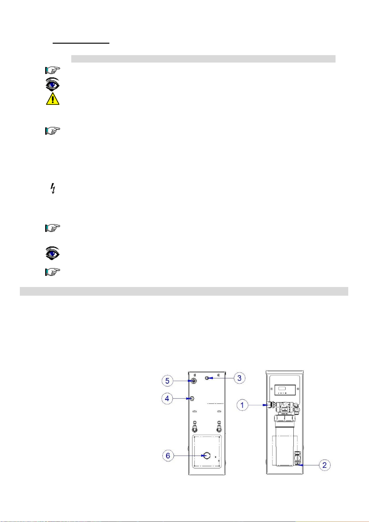
2.4 GENERAL DIMENSIONS ............................................................................................................... 7
2.5 INNER LAYOUT ....................................................................................................................... 7
3
INSTALLATION............................................................................................................................. 8
3.1 DRAIN BRACKET INSTALLATION .................................................................................................... 9
3.2 EXCHANGE OF THE CAPILLARY .................................................................................................... 10
4
FUNCTIONING.............................................................................................................................11
4.1 FIRST START-UP.....................................................................................................................11
4.2 NORMAL USE......................................................................................................................... 11
4.3 MIX....................................................................................................................................11
4.4 LOW PRESSURE ALARM .............................................................................................................11
4.5 LEAKAGE ALARM .................................................................................................................... 11
4.6 INACTIVITY........................................................................................................................... 11
4.7 ELECTRONIC BOARD FUNCTIONING ............................................................................................... 12
4.8 CONFIGURATION MENU............................................................................................................. 13
5
ORDINARY MAINTENANCE ..............................................................................................................14
5.1 REQUIRED TRAINING FOR MAINTENANCE TECHNICIANS ........................................................................ 14
5.2 RESPONSIBILITIES OF MAINTENANCE TECHNICIANS.............................................................................. 14
5.3 REPLACEMENT OF CARTRIDGE PROFINE FILTER.................................................................................15
5.4 PRELOAD OF THE EXPANSION TANK ..............................................................................................16
5.5 EQUIPMENT SANIFICATION .........................................................................................................16
6
TROUBLESHOOTING .....................................................................................................................17
7
DISPOSAL ..................................................................................................................................19
ATTACHMENT I –UE Declaration
........................................................................................................................................ 20
ATTACHMENT II –MAINTENANCE LOG
............................................................................................................................. 21

4
Cod. 2050-0001 Rev 1.1
1
GENERAL INFORMATION
1.1 MANUFACTURER / ASSISTANCE
BUILDER
ASSISTENCE
ARISTARCO Spa
Castelfranco Veneto (TV)
Personal Data of the Retail Seller
1.2 CERTIFICATIONS
EASY:FAST was manufactured in compliance with the following EU Directives:
Machines 2006 / 42 / UE
Low Voltage 2014 / 35 / UE
Electromagnetic Compliance 2014 / 30 / UE
RoHS2 2011 / 65 / UE
1.3 PURPOSE AND CONTENTS
This manual was written in order to supply the user with all the necessary information needed to facilitate
the autonomous and safe operation of this device. The manual contains information that is critical to the
operation and regular maintenance of the machine.
WARNING
This manual is addressed both to the users, for the parties expressly stated, andto
the technicians qualified for maintenance of the machine.
Before carrying out any work on the machine, both users and installers and qualified
technicians should read carefully the instructions contained in this manual.
Users can only perform the operations described in this manual and they have not to
perform tasks reserved to maintenance or qualified technician.
WARNING
This equipment needs regular maintenance in order to guarantee treated water
drinkability requirements and the maintenance of improvements as stated by the
manufacturer.
1.4 CARE AND STORAGE OF THE MANUAL
The instruction manual is an integral part of the machine and it must be be kept nearby, in a special
container and, above all, safe from liquids and anything else that could compromise its readability.
1.5 IMPORTANT SYMBOLS TO REMEMBER
GENERAL WARNINGS
This symbol Indicates warnings or key information regarding the operation of this device.
Please pay close attention whenever you see this symbol.
This symbol Indicates that specialized/portable equipment may be required to adjust or
repair the components of the device.
This symbol Indicates that a visual or in-depth inspection, etc. of the device may be
required.
INDICATIONS OF DANGER
This symbol Indicates General cautions; risk to the operator.
This symbol Indicates danger of electrical shock or electrocution.
RESTRICTIONS
This symbol indicates general restrictions.

5
Cod. 2050-0001 Rev 1.1
2
FEATURES OF THE EQUIPMENT
2.1 RECOMMENDED USE
EASY:FAST is equipment able to modify organoleptic and chemical characteristics of potable water, reducing
saline content.
It can be installed in home and in work place.
It can be used for the production of osmotic water for commercial and HO.RE.CA applications.
The equipment can be connected to dishwashers and coffee machines for cafés, hotels and restaurants.
2.2 FORBIDDEN USE
WARNING
Use for drinking purposes:
IT IS STRICTLY FORBIDDEN to use the equipment for the treatment of non-
drinking water.
IT IS STRICTLY FORBIDDEN to use the equipment in the absence of periodic
maintenance.
IT IS STRICTLY FORBIDDEN to use the equipment in hygienic conditions or
environments that aren't in compliance with those indicated in this manual.
IT IS STRICTLY FORBIDDEN to supply the equipment with waste water, sea water
or water in chemical, physical and biological that do not meet the drinkability
limits. (Industrial waste or chemical processing).
The device can be used by children aged less than 8 years, and by people with
reduced physical, sensory or mental capabilities, or lack of experience or
knowledge, only under surveillance or after their having received instructions
about safe use and understood of the dangers inherent in it.
WARNING
The company is not responsible for any damage to persons or property resulting from
failure to follow these directions.

6
Cod. 2050-0001 Rev 1.1
WARNING
* The percentage of dissolved salts and other rejected elements is influenced by the quality
of the water, the temperature, the pressure and the totality of dissolved salts and it is
different depending on the types of salts or elements.
** In the case of near-limit water use, contact your dealer for the tests.
2.3 TECHNICAL SPECIFICATIONS
EASY:FAST
TECHNICAL SPECIFICATIONS
Height x Width x Depth (mm)
168x515x476
Weight (kg)
20
Approved Decibel Level under normal operating
conditions (db)
<70
Membranes (nr. 4)
TWB2A1
Carbon Block filter
Profine® BLUE small
WATER SUPPLY SPECIFICATIONS
Water quality
Drinkable
Minimum water temperature (°C)
5
Maximum water temperature (°C)**
35
Minimum inlet capacity (l/h)
400
Maximum inlet pressure
500 kpa
Minimum inlet pressure
150 kpa
LOCATION SPECIFICATIONS
Maximum relative humidity (%)
90
Minimum location temperature (°C)
5
Maximum location temperature (°C)
40
POWER SUPPLY SPECIFICATIONS
Power supply type
MONOPHASE + GROUND
Nominal power (V)
230
Frequency (Hz)
50/60
Absorbed current (A)
1.8A
Power (W)
180W
Fuse type (electronic board)
T3.15A
PERMEAT CHARACTERISTICS
Maximum capacity at 10° C (l/h)
c.a 140
Flow rate with back pressure of 0.3 MPa at 15 ° C (l/h)
c.a 110
Recovery percentage (%)*
25-30% with hard water
40% with medium-hard water
55-60% with soft water
AUTONOMY AND REPLACEMENT CONDITIONS
Profine® BLUE small
Max.100 h
Inverse osmosis membranes
Max 3 year
Vane pump and solenoid valve
2000 ore with treated water

7
Cod. 2050-0001 Rev 1.1
2.4 GENERAL DIMENSIONS
2.5 INNER LAYOUT
1.
By-pass valve and mix
2.
Inlet solenoid valve
3.
Maximal pressure switch
4.
Minimal pressure switch
5.
Permeate block
6.
Membranes
7.
Expansion tank
8.
Expansion tank charge
9.
PROFINE® BLUE SMALL filter
10.
PROFINE® head
11.
Electronic board
12.
Pump

8
Cod. 2050-0001 Rev 1.1
3
INSTALLATION
WARNING
Equipment installation must be performed by qualified technical personnel; detailed
instructions for installation are in the “Technical Manual ".
User should not perform equipment installation.
The room in which the appliance is installed must have a floor drain to prevent
damage to persons or property in case of flooding.
Install the device in a cool, dry, well-ventilated area. Interception and by-pass valves,
display, power plug and pre-filter must be visible and accessible to the user.
Use washing machine pipes conforming to EN61770 and that have a diameter not lower
than DN10. Do not reuse old or frayed pipes.
To install the device in accordance with EN 1717 and WRAS, order the accessories
separately; install upstream of the equipment a certified anti-pollution device <CA> and
an air interruption in drain.
The electrical power socket must be in compliance with the specifications listed in
the CE plate, with an efficient ground and protected by 0.03 mA differential switch. If
the power cord is damaged, it must be replaced by the manufacturer, dealer or a
similarly qualified person so as to avoid any safety risks.
The machine’s power supply must be protected against overcurrent (short circuits
and overloads) by fuses or suitable thermal magnetic circuit breakers. These must
be assembled on a single-core disconnecting system, which has a contact gap of at
least 3 mm.
Do not subject the device to excessive temperature changes that may create
condensation inside, which may damage the electrical parts.
The equipment can be installed in horizontal or vertical position, with the cover
oriented upwards, every other position is prohibited.
Do not obstruct the rear ventilation grills.
Be careful not to bend or clog the drain pipe.
We recommend installing a pressure gauge on the pump delivery line to check the
operating pressure
INSTALLATION CONNECTIONS
1.
Water Inlet ¾” G M
2.
Filter first washing”
3.
Bypass valve and mix
4.
Power supply socket
5.
Quick release drain ¼
6.
Permeate outlet ¾” G M

9
Cod. 2050-0001 Rev 1.1
Install the drain bracket on the 40mm diam. sink drain siphon.
Check that the seal rests properly on the pipe and the bolts are tight.
Remove the nut of the drain.
By using a 2 mm drill bit, drill a hole in the exhaust pipe of the siphon, at the nut
just disassembled.
Insert the drain pipe into the nut and tighten the nut on the bracket.
Tighten the nut and install the valve with the arrow pointing towards the
bracket, as close as possible to the drain.
1
2
5
3
4
6
3.1 DRAIN BRACKET INSTALLATION
1.
Drain siphon
2.
Drain clamp
3.
Screw
4.
Drain pipe nut
5.
Drain pipe ¼”
6.
Check valve ¼”

10
Cod. 2050-0001 Rev 1.1
WARNING
Remove the locking clip.
Push the fitting collet and remove the white capillary.
Push the capillary inside the fittings.
Put the locking clip below the fitting collets.
3.2 EXCHANGE OF THE CAPILLARY
PH
9,5
BLACK 95h
WHITE 85h
WHITE 85h
SOFTENER+BLUE
105h
9
8,5
BLUE 105h
BLACK 95h
8
WHITE 85h
7,5
BLACK
95h
7
HARDNESS
°F
<11
12--25
26--35
36--44
°Dh
<5
6--15
16--20
21--25
WARNING
After replacing the capillary, set the filter change time in the control unit (§ 4.8).
WARNING
BLUE CAPILLARY = recovery 55-60% at 15°C
BLACK CAPILLARY = recovery 35-40% at 15°C (softener recommended) (standard)
WHITE CAPILLARY = recovery 25-30% a 15°C (softener recommended)
SOFTENER = softener or required antiscalant dosing
The equipment must not be installed with inlet water> 1200 mS or> 35 ° dH.

11
Cod. 2050-0001 Rev 1.1
WARNING
If leakage alarm repeats, disconnect the power, open the machine and check for
leakages.
Machine opening and leakage inspection can be done by qualified personal only.
4
FUNCTIONING
4.1 FIRST START-UP
WARNING
The first start-up of the machine must be done by the installer.
The installer checks the correct functioning of the machine.
Insert the power plug in a grounded socket 230V 50Hz; the machine is ready to operate. It
is recommended to let the water run for at least an half of hour, to drain out the
substances for the preservation of the membranes.
Check for leaks from the hydraulic circuit.
Make the sanitation of the machine as described in paragraph § 5.5.
4.2 NORMAL USE
For normal use of is necessary to keep the machine always on.
The machine will automatically switch to each rinse of the dishwasher.
Every 6 hours, the machine automatically opens the inlet valve, so that the membranes are washed for 2
minutes.
4.3 MIX
The mixing valve, installed on the back of the machine has a dual function, in operation allows to vary the
salinity of the water produced: it uses filtered water and it mixes it with water permeate downstream of the
membranes . This device must be calibrated during installation.
Emergency BY-PASS function: with unplugged power supply system, when it's open, it lets the regular
operation of the dishwasher with cold water.
4.4 LOW PRESSURE ALARM
In case of insufficient input pressure, the equipment stops and emits three BEEPs, displaying the alarm on the
display. After a minute it automatically re-activates. The minimum pressure switch is ignored for 20 seconds
from start-up. In the case of low consecutive pressure alarms, the automatic reset delay increases.
4.5 LEAKAGE ALARM
The machine has two leakage sensors inside. In chase of leakage, the machine makes a long BEEP and stop
the machine. To restart the machine, disconnect and reconnect the power plug pressing the button.
When the alarm is preset the card makes three BEEPs.
4.6 INACTIVITY
WARNING
We recommend that, whenever the unit remains stationary for a period of almost one
week, let the water run for at least 10 minutes prior to sampling.
It is advisable to make a sanitation plant every six months and during routine
maintenance.
To perform this operation, contact the service as it must be performed by skilled
personnel / installers.
WARNING
Do not close the tap to avoid dehydration of the membranes because this can
compromise their operativity.

12
Cod. 2050-0001 Rev 1.1
4.7 ELECTRONIC BOARD FUNCTIONING
key.
When the board is in normal operating mode, the name of
the equipment or of the dealer is displayed.
Pressing the key the instantaneous conductivity is
displayed.
With board in standby mode, you can scroll the menu with
and ; keys; enter in the menu with the
Pressing key the software release is displayed.
It performs the flushing of the membranes for 2 minutes by
opening the inlet solenoid valve.
It resets the hours of operation of the filter. Confirm with
.
It displays the remaining hours before the filter change.
It displays the hours spent from the filter change.
It activates the by-pass EV2
solenoid valve.
M
i
k
r
o
t
ec
V
e
r
2
.
04
E
A
SY
:
F
A
S
T
F
l
u
s
h
.
M
a
nu
a
l
F
l
u
s
h
.
press >
R
ese
t
T
R
ese
t
F
il
t
e
r
By
pass
d
i
sa
b
By
pass
funct
By
pass
e
n
a
b
l
e
u
S
/
c
m
0050
E
A
SY
:
F
A
S
T
T
To
t
a
l
0000:00
T RES
0000:00

13
Cod. 2050-0001 Rev 1.1
4.8 CONFIGURATION MENU
In order to have access to the programming pages, the key while you connec
the supply plug.
Subsequently the board will require pressing the key to confirm access to the
programming.
The first page allows to reset the hour counter by pressing
the
key pressing the key again toconfirm.
It can enable / disable the automatic bypass activated by
the solenoid valve connected to the output EV2,
commanded by the entrance P.EV2 pressure.
Select the saved names with the and keys and
confirm with the key.
Select functioning by time or without time limit with the
and keys and confirm with the key.
Access the modification of the litres/hour conversion
parameter with the key. Modify the value with the
and keys and confirm with the key
Modify the “filter hours capacity” parameter with the
key. Modify the value with the and keys and
confirm with the key.
Modify the language parameter with the key . Set the
language with the keys
and
and confirm with
the key .
Press >
R
ese
t
T
R
ese
t
f
il
t
e
r
By
pass
e
n
a
b
l
e
E
A
SY
:
F
A
S
T
S
e
tt
i
ng
c
u
s
t
o
m
e
r
S
e
tt
i
ng
Press
>
mode
no
li
m
i
t
S
e
tt
i
ng
mode
.
S
e
tt
i
ng
K convrs
S
e
tt
i
ng
t
i
m
e
t
i
m
e
0070funz
K Convrs
0060nvrs
E
ng
li
s
h
S
e
tt
i
ng
Language
S
e
tt
i
ng
By
pass

14
Cod. 2050-0001 Rev 1.1
5
ORDINARY MAINTENANCE
5.1 REQUIRED TRAINING FOR MAINTENANCE TECHNICIANS
Maintenance personnel must possess the following qualifications as prescribed in this manual:
The required technical knowledge to understand the concepts outlined in this manual.
Knowledge of basic hygiene
General familiarity with the device, in addition to a basic knowledge of troubleshooting electrical
and hydraulic problems.
5.2 RESPONSIBILITIES OF MAINTENANCE TECHNICIANS
The overall maintenance plan, described in this chapter, must be rigidly adhered to as indicated in the above
paragraph, in order to maintain the efficient operation of the device, thereby guaranteeing continued water
quality.
WARNING
The tasks listed in the box below must be performed by qualified technical personnel,
strictly in accordance with the manual, exclusively using approved parts and materials.
Otherwise the guarantee will be null and void. The maintenance performed must always
be documented properly and signed by the technician in the space provided on the
attached maintenance log.
It is advisable to carry out routine maintenance at least 1 time every 6 months even if you
have not reached the limit of exhaustion of the filters.
WARNING
This equipment should be serviced periodically to ensure that water supplied by it
maintain its characteristics of drinking water.
PART TO CONTROL
CONTROL
FREQUENCY
Visual inspection integrity and
conservation status
Machine
Cleanliness
6 MONTHS
Functional testing
Disinfection of hydraulic circuit
preload of expansion tank
Activated carbon filter
Replacement
Machine
Calibration check, clean conductivity
probe connectors
In chase of malfunction or
2000 working hours (*)
Membranes
Replacement
In chase of high conductivity
or low flow rate reduction of
30%(*)
Vane pump and solenoid valve
Replacement
2000 working hours
(*)Special water conditions may require more frequent maintenance.
WARNING
Use only original spare parts.
WARNING
The internal electrical system of the machine is powered by 230 Volts.
Prior to opening the device, remove the cover and/or panels and/or the protective
grill, ensuring that the plug has been removed from the electrical outlet.
WARNING
DO NOT use corrosive products, acids, steel wool or wire brushes to clean the device.
DO NOT use low or high pressure jets of water when washing the device.

15
Cod. 2050-0001 Rev 1.1
WARNING
The equipment must be accompanied by external pre-filter that can
guarantee dechlorination and filtration of raw water.
It’s recommended to use the filter PROFINE® BLUE Small
5.3 REPLACEMENT OF CARTRIDGE PROFINE FILTER
To replace the pre-filter follow these steps:
Turn off the machine by pressing the button
Turn used up cartridge ¼ " turn to the left and pull it out by pulling it down from the head.
Remove the protective cap from the new cartridge and write down the date of installation of the new
cartridge in the provided space.
Insert the new cartridge without forcing it in any way, making sure to enter the tabs in their own seats
in the head and turn it 90 ° to the right until it stops without forcing.
To facilitate the entrance you can moisten slightly the seals, placed on the cartridge, with water or
cooking oil.
The removed cap can be used to seal the used up cartridge.
Open the 10mm intermediate valve located in the outlet of the pre-filter head and
place it in a drain point, then open the tap located upstream of the machine. Allow
at least 20 liters of water to wash the new pre-filter and close the valve.
Turn on the machine by pressing the button and carry the filter time reset of
the board out.

16
Cod. 2050-0001 Rev 1.1
5.4 PRELOAD OF THE EXPANSION TANK
For the preload of the expansion tank follow these steps:
Disconnect the power supply
Empty the expansion tank completely supplying water.
With the use of a compressor and a tire gun, bring the tank preload pressure to 0.1 MPa.
Put the machine in the original position and connect the power plug.
5.5 EQUIPMENT SANIFICATION
Run the machine sanitation before each filter change, and in any case at intervals not
exceeding 6 months.
Run also sanitizes after prolonged disuse of the machine and at the first starting.
All sanitation operations must be performed by qualified personal.
Use extreme caution in the use and dosage of chemicals.
Use protective clothing to the skin, hands and eyes as shown in the safety data sheet
of chemicals used.
Close the mix valve on the front of the machine and fill a tank with 10 liters of osmotic
water.
Add hydrogen peroxide 10 vol (3%) to achieve a concentration of 0.2% by weight:
dose 650 ml of hydrogen peroxide at 10 volumes per 10 liters of osmotic water or
dose 250 ml of hydrogen peroxide at 24 volumes per 10 liters of osmotic water or
dose 180 ml of hydrogen peroxide at 36 volumes per 10 liters of osmotic water or
dose 50 ml of hydrogen peroxide at 130 volumes per 10 liters of osmoticwater.
Close the water intake valve and disconnect the water intake pipes, drain and permeated
by the machinery, put a bridge on the low pressure switch.
Connect the water pipes of entry, drain and permeated by the machine at the tank.
Slightly open the mixing valve, turn the machine on and recirculate the sanitizing solution
for at least 10 minutes.
Turn off the machine and wait 10 minutes until the solution act.
Reconnect the pipes of drain and permeate, previously unplugged by the machine.
Turn on the machine and deliver up to empty the tank of the sanitizing solution.
Replace the filter and reconnect the minimum pressure switch.
Turn on the machine and deliver water for at least 10 minutes to drain any residual
sanitizing solution from the machine.
In the event of system resting up, carry out the standard sanitation cycle § 5.5.
Disconnect hydraulically the system and keep it away from frost or excess heat,
every 6 months of stopping you must carry out a new disinfection cycle.

17
Cod. 2050-0001 Rev 1.1
6
TROUBLESHOOTING
The operations indicated must only be carried out by qualified personnel, with the
exception of those marked *.
Problem:
The display does not turn on.
Cause
Solution
No electricity supply
Make sure the plug is inserted and there is electricity supply.
Board in “OFF” position.
Press ON-OFF switch.
Internal electrical fault.
Disconnect the plug, open totally the MIX valve and contact service.
Problem:
Intervention of fuse or protection thermal switch.
Cause
Solution
Internal electrical fault.
Disconnect the plug, open totally the MIX valve and contact service.
Problem:
Intervention of protection differential switch (distribution board)
Cause
Solution
Internal electrical fault.
Disconnect the plug, open totally the MIX valve and contact service.
Problem:
The display shows “Alarm Leakage.”
Cause
Solution
Leakage
Reset the alarm, see § 4.6. If the alarm repeats or in case of water
leakage, close the upstream water supply valve, unplug it and contact
the assistance service.
Problem:
With the display turned on and working, the dishwasher opens the load
solenoid valve, osmosis drains water but the engine will not start.
Cause
Solution
Engine fault
Disconnect the plug, open totally the MIX valve and contact service.
Problem:
With the display turned on and working, the engine starts but after few
seconds the display will show "Alarm p. min” and the machine stops.
Cause
Solution
Closed inlet water valve.
Check that upstream inlet water valve is open.
Low inlet pressure
Check the pressure upstream of the device.
Clogged filter.
Check the pressure downstream of the filter, if clogged, replace it.
Bended/crushed pipe.
Make sure that inlet water pipes are not bended or crushed.
Solenoid/faulty card.
Disconnect the plug, open totally the MIX valve and contact service.
We recommend installing a pressure gauge on the pump delivery line to check the
operating pressure

18
Cod. 2050-0001 Rev 1.1
Problem:
The machine produces little water, the dishwasher indicates alarm.
Cause
Solution
Clogged filter.
Check the pressure downstream of the filter, if clogged, replace it.
Damaged pump.
Disconnect the plug, open totally the MIX valve and contact service.
Clogged Membranes.
Disconnect the plug, open totally the MIX valve and contact service.
Clogged solenoid valve.
Disconnect the plug, open totally the MIX valve and contact service.
Problem:
Treated water has an unpleasant taste.
Cause
Solution
Used up filter.
Replace the filter, and then perform loading and unloading the dishwasher
tank twice.
Bacterially contaminated
equipment.
Contact assistance service to perform the sanitization of the equipment.
Problem:
With the dishwasher switched off, the machine starts for few seconds.
Cause
Solution
The check valve is faulty.
Contact assistance service.
Leak in hydraulic circuit.
Contact assistance service.
Problem:
With dishwasher in loading phase, with display on, the osmosis doesn’t
start.
Cause
Solution
Incorrect connections.
The in/out links were inverted.
Maximum pressure switch, or
wiring failure.
Disconnect the plug, open totally the MIX valve and contact service.
Problem:
When the dishwasher is not loading water, osmosis doesn’t stop.
Cause
Solution
Maximum pressure switch, or
wiring failure.
Disconnect the plug, open totally the MIX valve and contact service.
Incorrect connections.
The in/out links were inverted.
Problem:
With the valve opened, the machine operates in a discontinuous way, going
by in fits and starts.
Cause
Solution
Maximum pressure set at too
low a pressure.
Disconnect the plug, open totally the MIX valve and contact service.
Bended/crushed pipe.
Make sure that inlet water pipes are not bended or crushed.
Problem:
Pressure too low.
Cause
Solution
Preload too low.
Run the preload of the expansion tank.
Calibration of high
pressure switch too low.
Disconnect the plug, open totally the MIX valve and contact
service.

19
Cod. 2050-0001 Rev 1.1
7
DISPOSAL
WASTE OF ELECTRICAL / ELECTRONIC EQUIPMENT
(UK) EU directive 2002/96/EC classifies this product as an electrical or electronic
tool.
Do Not dispose of this tool as unsorted municipal waste.
Dispose of this tool at a collection or recycling center according to local and national
law.
The consumer has an important role in reducing the disposal of waste by returning
waste electronic/electrical tool for recycling. Recycling avoids the dispersion of
hazardous materials into the municipal waste stream.
The crossed-out bin symbol reminds the user not to dispose of this product as unsorted municipal
waste.
If disposed of privately, exhausted filters and membranes are to be considered not
dangerous solid waste. (CER 15.02.03 or 16.02.16) If intended as a replacement, subject
to periodic replacement.
If disposed of by companies, the filters are CER 19.09.04, the membranes CER 15.02.03.
At the end of the lifetime, the equipment must be disposed of at an authorized
dismantling and disposal center (CER 20.01.36).
At the end of the lifetime, the equipment must be disposed of at an authorized
dismantling and disposal center (CER 20.01.36).

20
Cod. 2050-0001 Rev 1.1
ATTACHMENT I –UE Declaration
1. Equipment/Product Model
EASY:FAST
2. Name and address of the manufacturer or his authorized representative:
KASTEL
Castelfranco Veneto (TV)
3. This declaration of conformity is issued under the sole responsibility of the manufacturer.
4. Aim of the declaration:
Production year 2017 and subsequent
5. The object of the declaration described above is in conformity with the relevant Union harmonization legislation
-2006/42/UE (machines)
-2014/30/UE (EMC)
-2014/35/UE (LVD)
-2011/65/UE (RHOS2)
References to the relevant harmonized standards used, including the date of the rules, or reference to other technical
specifications in relation to which conformity is declared, including the date of the specifications:
EN 62233:2008/AC:2010
EN 55014-1:2006/A1:2009
EN 55014-1:2006/A2:2011
EN 55014-2:2015
EN 61000-3-3:2013
EN 60335-1:2012/AC:2014
EN 60335-2-40:2003/A13:2012/AC:2013
Castelfranco Veneto, KASTEL
The Legal Representative
Table of contents
Popular Water Filtration System manuals by other brands

GE
GE GXWH40L installation instructions

Ecosoft
Ecosoft MO6500BWTSS instruction manual

Hamilton Beach
Hamilton Beach AquaFusion 87325 Replacement

Jandy
Jandy Jandy Pro Series Installation and operation manual

ELECTOR
ELECTOR REFILL plus Series operating manual

Oerlikon
Oerlikon ARS 16-25 operating instructions

WaterLogic
WaterLogic WL3 FX manual

Global Industrial
Global Industrial 641753 manual

Life Ionizers
Life Ionizers M7 X user manual

3M
3M Aqua-Pure AP430SS Installation and operating instructions

Pure Blue H20
Pure Blue H20 PB-TLRO4H50T instruction manual

LG
LG Premium 5231JA2002A-S installation and replacement