2 / 4
DANGER!
Danger to life from electric shock when touching electrical installations!
►Disconnect all devices and units from the power supply during installation.
►In order to comply with the regulations for outdoor installation according to DINVDE0100Part610, it is recom-
mended to have a residual current circuit breaker with a residual current of 0.03 A installed.
►Make sure that installation and connection are only carried out by qualified specialist personnel.
►Make sure that modifications to the electrical installation are only carried out by a specialist. Do not make any unau-
thorised modifications yourself.
Installation and Safety Instructions
WARNING!
Risk of severe injuries during installation due to falling from or through the roof or due to falling parts!
►Wear stable shoes with non-slip soles.
►Use a working platform.
►Make sure that the person carrying out the installation or repair has a secure position to stand and hold on whilst
working.
►Make sure that the person carrying out the installation or repair does not suer from vertigo and can move around
safely on the roof or installation site.
►Make sure that the roof is suciently strong and stable.
►Make sure that there is nobody underneath the antenna during installation/de-installation.
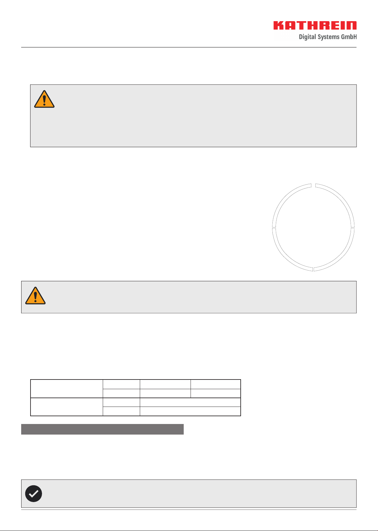
Installing the Reflector Heating
Required tools and equipment
•Knife
•Scissors
Installing the heating mats
Processing temperature
The most favourable processing temperatures (object temperature and ambient temperature) are between +15°C and +30°C.
Processing below these temperatures is not recommended. Below the recommended temperatures, the adhesive may become too
hard and thus not achieve the desired adhesion.
The build-up of condensation must be avoided in any case. Condensation may build up when the adhesive tape and/or the surfaces
to be bonded are moved from a cold to a warmer environment. If this is the case, sucient time must be allowed after transport and
before bonding, so that all joining parts have the same temperature in the range indicated above.
Intended Use
ESO 180 H and ESO 180 HL (performance-increased version) are reflector heaters for the CAS 180 antenna. They are used to prevent
snow and ice formation on the antenna reflector surface which could lead to interruptions in satellite reception. Any other use,
or failure to comply with these instructions or documentation and instructions enclosed with the devices, will result in voiding of
warranty and guarantee. The following circumstances result in the loss of all warranty and liability claims towards the manufacturer:
►Improper installation
►Use of non-specified mounting materials which cannot guarantee the mechanical safety
►Structural changes or interference with the components and mounting accessories in the kit which could endanger both the
mechanical and functional reliability
►Failure to observe the installation and safety instructions in this manual
1. Clean and degrease the antenna back panel.
The surface to be bonded must always be dry, free from dust, grease, oil, oxides, separating agents and other contaminants.
Isopropanol, ethanol, acetone, ethyl acetate, toluene or petrol can be used to remove dust, grease, oil, separating agents and
other contaminants. Other standard cleaning agents that do not leave any residues are also suitable. Please observe the respec-
tive safety regulations of the manufacturers of the solvents and cleaning agents.