Kato KFS-20 User manual

8
KFS-20 PROPERTIES
Characteristics
Specifications
Length
8.85 in (225 mm)
Grip Diameter
1.28 in (32.7mm)
Output Torque Range
.88-.62 lbf-in
.1-.7 N・m.
1-7 kgf・cm
Rotation
(Low Setting, No Load)
480 RPM
INSTRUCTIONS FOR USING KATO COILTHREAD®TOOLS
THE FOLLOWING INSTRUCTIONS ARE APPLICABLE FOR THE
KATO KFS-20 BRUSHLESS ELECTRIC DRIVER (CT5420) & T-45BL POWER SUPPLY
Page 1

IN THE BOX
•1.5-meter driver cord and 1.8-meter Power Supply cord.
•2 Springs - 1 Blue (Meant for 2-56, 4-40, 6-32 & M2.5 - M4).
- 1 Light Silver (Meant for 6-32 - 1/4” & M4 - M6).
•Hex Shaft Magnet (located inside the hex shaft).
•Magnet Removal Screw.
•T-45BL Power Supply (see page 5).
•Mounting Bracket with Screw
DRIVER FEATURES
The CT5420 Electric Driver features a Brushless DC motor, which requires less maintenance over the
previous CT5408, CT5406 or CT5405 drivers. The driver features a Forward/Neutral/Reverse Switch.
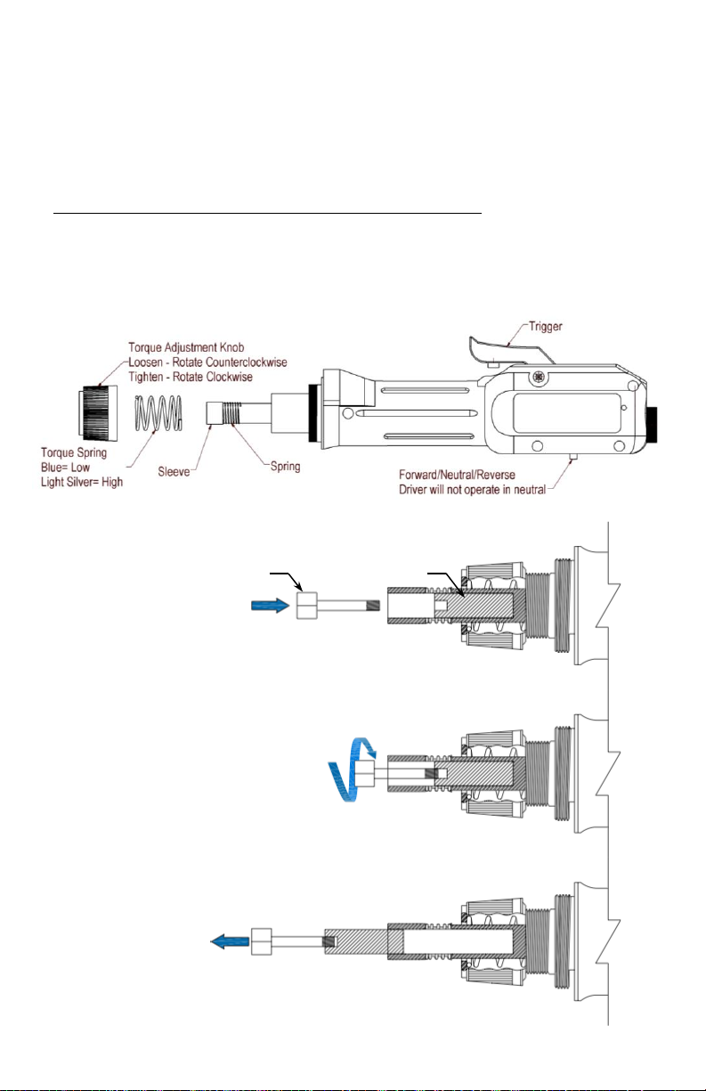
TORQUE SPRING CHANGE
The CT5420 Electric Driver includes 2 Torque Springs. Sizes 2-56, 4-40, 6-32, M2.5 - M4 are
designed to be used with the Blue Torque Spring. Sizes 6-32 through 1/4”, M4 - M6 are designed to
be used with the light silver Torque Spring. To change the Torque Springs please follow the steps
below:
1. Loosen the Torque Adjustment Knob by pushing the knurl collar down and rotating it
counterclockwise until the knob comes free (see Figure 2).
2. Replace the Torque Spring for the corresponding size.
3. Thread the Torque Adjustment Knob back onto the driver and tighten to the desired torque.
ELECTRIC DRIVER ASSEMBLY FOR 2KHE & KHE SERIES TOOLS
4. Attach the power cord from the KATO T-45BL Power Supply (included) to the KFS-20 electric
driver and tighten the knurled rings on both ends of the cord (finger tight).
5. Plug the Power Supply into a standard 110 VAC outlet.
6. Set the Power Supply output to the LOW speed setting. Make sure the power is in the OFF
position until ready for use.
7. Pull the sleeve back on the KFS-20 driver and insert the Mandrel into the hex shaft.
8. Ensure the electric driver directional switch is in the FOR (Forward) position. Note: This switch is
located on the side opposite the Trigger. For insert installation this switch should always be set in
the “FOR” position. The driver will reverse direction automatically once the insert is installed
properly and the installation torque is adjusted correctly. If the directional switch is set to Neutral,
the KFS-20 will not operate.
9. With the Power Supply set to LOW, turn the power switch to ON and press the trigger on the
driver to test the operation of the unit.
10.For additional information please refer to the 2KHE or KHE series instructions.
ELECTRIC DRIVER ASSEMBLY FOR 2KPE & KPE SERIES TOOLS
11.With the power off, insert the Magnet Removal Screw into the hex shaft and thread it into the
Magnet, located inside the hex shaft (see Figure 3).
12.Pull the Magnet out and set it in a safe place.
13.Attach the power cord from the Power Supply to the electric driver and tighten the knurled ring on
both ends (finger tight).
14.Plug the Power Supply into a standard 110 VAC outlet.
15.Set the Power Supply output to the LOW speed setting. Make sure the transformer power is
“OFF” until ready for use.
16.Thread the prewinder adapter onto the driver (L.H. Threads).
17.Unscrew the Retainer Nut from the Prewinder Adapter (L.H. Threads).
BEFORE YOU BEGIN PLEASE REVIEW…
•Proper hole preparation procedures.
•A step by step instructional video can be found in the KATOpedia section of
the KATO website www.katofastening.com.
Page 2

18.Install the Front-End Assembly (2KPE or KPE series) and rethread the Retainer Nut onto the
Prewinder Adapter.
19.Ensure the electric driver directional switch is in the “FOR” (Forward) position. Note: This switch is
located on the side opposite the Trigger. For insert installation this switch should always be set in
the “FOR” position. The driver will reverse direction automatically once the insert is installed
properly and the installation torque is adjusted correctly. If the directional switch is set to Neutral,
the KFS-20 will not operate.
20.For additional information please refer to the 2KPE or KPE series instructions.
TORQUE ADJUSTMENT
1. Always use the minimum amount of torque that will install the insert. Start with the lowest torque
setting on the electric driver. To adjust the torque, pull back on the knurled collar while
simultaneously turning the Torque Adjustment Knob. Tighten the collar to increase torque and
loosen to decrease torque. The collar will lock into place every 180°.
2. Start with the lowest torque setting and increase as required to reach the minimum installation
torque. This will minimize the possibility of damage, or wear, to the Mandrel or Pawl and extend
tool life.
Page 3
Magnet Removal Screw
Hex Shaft Magnet
Figure 3 –Magnet Removal
Figure 2 - Spring Change

SAFETY
Always wear eye protection when working with KATO tools.
REPAIRS AND PARTS REPLACEMENT
Any repairs should be done by an authorized dealer or trained professional.
FOR ASSISTANCE CONTACT THE KATO TECH GROUP AT:
Phone (757) 873-8980
Email: support@katofastening.com
or, visit us online www.katofastening.com
TIPS & TRICKS
Having difficulty getting the insert started? Try one or more of these helpful tips:
•If the Mandrel seizes when it fully recedes into the hex shaft, tap the trigger a
few times as if sending Morse code.
•Dipping the insert in Alcohol or other non-residual solution will provide
lubrication and may help facilitate installation. USING ALCOHOL ON LOCKING
INSERTS WILL CAUSE THE RED DYE TO BLEED.
Page 4
Figure 4 - Exploded View of CT5420

KATO T-45BL POWER SUPPLY
Characteristics
Specifications
L x H x W
5.75”x 1.80”x2.82”
Weight
.60 lb.
Input Voltage
100- 240 VAC 47-63 Hz
Output Voltage
20 VDC/30 VDC
Amperage
0.75 A
Page 5

IMPORTANT NOTES
The T-45BL is only compatible with the CT5420 Brushless Electric Drivers.
The Power Supply can be used in US and Europe since the input voltage
can range from 100 VAC to 240 VAC (47-63 Hz). For the European market,
the Power Supply comes with a VDE style plug cord., see Figure 7.
TRANSFORMER SETUP
1. The T-45BL Power Supply should be securely fixed to the work table.
Fasten the Mounting Bracket to the Power Supply using the included screw and secure
it flat to the work table or wall, see Figure. 5.
2. Turn the DC Output Switch to Low and the Power Switch to Off, see Figure 6.
3. Connect the electric driver’s power cord to the Power Supply and tighten using the knurl ring.
Make sure both ends are connected.
4. Connect the power cord to the back of the Power Supply and plug it into a 120 VAC outlet.
5. Turn on the Power Supply once you are ready to operate the driver.
OPERATION
The T-45BL Power Supply is designed to operate the CT5420 electric drivers only. When the Power
Switch is turned On, the Power Indicator illuminates. This indicates that the Power Supply is
energized, and the operator can begin installation. After the insert has been installed, the driver
senses the spike in torque and sends a signal back to the Power Supply. The Power Supply reverses
the driver and the mandrel is threaded out. When the trigger is released, the Power Supply resets.
Note: Do not turn off the Power Supply while the driver is operating. This may cause damage to the
driver and/or the Power Supply unit.
BEFORE YOU BEGIN PLEASE REVIEW…
•Proper hole preparation procedures.
•A step by step instructional video can be found in the KATOpedia section of
the KATO website www.katofastening.com.
Page 6
Figure 5
Secure flat to the work station or wall.
Figure 6
Figure 7

SAFETY
Always wear eye protection when working with KATO tools.
MAINTENANCE
KATO T-45BL requires no maintenance.
REPAIRS AND PARTS REPLACEMENT
Any repairs should be done by an authorized dealer or trained professional. For additional information
contact KATO Fastening Systems at support@katofastening.com
FOR ASSISTANCE CONTACT THE KATO TECH GROUP AT:
Phone (757) 873-8980
Email: support@katofastening.com
or, visit us online www.katofastening.com
Page 7

Notes
Page 8
©2019 KATO Fastening Systems, Inc.
Table of contents
Other Kato Tools manuals