Kaye LTR -90 User manual

Validation
M4590E Rev. B
June 2014
Amphenol
Advanced Sensors
Kaye LTR -90
Operating Manual
X0395, X0395CE, X0395JP, X0395AS

Copyright © 2014 Amphenol Thermometrics, Inc.
967 Windfall Road
St. Marys, Pennsylvania 15857
Web: www.amphenol-sensors.com

©2014 Amphenol Thermometrics, Inc.. All rights reserved.
Technical content subject to change without notice.
A
mphenol
Advanced Sensors
Kaye LTR -90
Ultra Cool Dry Well Calibrator
Operating Manual
M4590E Rev. B
June 2014

ii
[no content intended for this page]

Kaye LTR -90 Operating Manual iii
Contents
Chapter 1. Product Overview
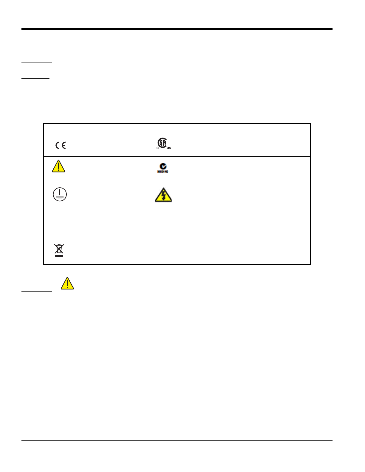
1.1 Safety Information. . . . . . . . . . . . . . . . . . . . . . . . . . . . . . . . . . . . . . . . . . . . . . . . . . . . . . . . . . . . . . . . . . . . . . . . . . . . . . . . . . . . . .2
1.2 Contact Amphenol Advanced Sensors Customer Service . . . . . . . . . . . . . . . . . . . . . . . . . . . . . . . . . . . . . . . . . . . . . . . . .4
1.3 Calibration and Repair Information . . . . . . . . . . . . . . . . . . . . . . . . . . . . . . . . . . . . . . . . . . . . . . . . . . . . . . . . . . . . . . . . . . . . . .4
Chapter 2. Specifications
2.1 Introduction. . . . . . . . . . . . . . . . . . . . . . . . . . . . . . . . . . . . . . . . . . . . . . . . . . . . . . . . . . . . . . . . . . . . . . . . . . . . . . . . . . . . . . . . . . . .5
2.2 Specifications . . . . . . . . . . . . . . . . . . . . . . . . . . . . . . . . . . . . . . . . . . . . . . . . . . . . . . . . . . . . . . . . . . . . . . . . . . . . . . . . . . . . . . . . . .6
2.2.1 Base Unit Specifications . . . . . . . . . . . . . . . . . . . . . . . . . . . . . . . . . . . . . . . . . . . . . . . . . . . . . . . . . . . . . . . . . . . . . . . . . . .6
Chapter 3. Quick Start
3.1 Unpack and Inspect . . . . . . . . . . . . . . . . . . . . . . . . . . . . . . . . . . . . . . . . . . . . . . . . . . . . . . . . . . . . . . . . . . . . . . . . . . . . . . . . . . . .9
3.2 Placement . . . . . . . . . . . . . . . . . . . . . . . . . . . . . . . . . . . . . . . . . . . . . . . . . . . . . . . . . . . . . . . . . . . . . . . . . . . . . . . . . . . . . . . . . . . . .9
3.3 Connect to Mains Power . . . . . . . . . . . . . . . . . . . . . . . . . . . . . . . . . . . . . . . . . . . . . . . . . . . . . . . . . . . . . . . . . . . . . . . . . . . . . . .10
3.4 Turn On the Product . . . . . . . . . . . . . . . . . . . . . . . . . . . . . . . . . . . . . . . . . . . . . . . . . . . . . . . . . . . . . . . . . . . . . . . . . . . . . . . . . . .10
3.5 Change Language. . . . . . . . . . . . . . . . . . . . . . . . . . . . . . . . . . . . . . . . . . . . . . . . . . . . . . . . . . . . . . . . . . . . . . . . . . . . . . . . . . . . .10
3.6 Set Display Contrast . . . . . . . . . . . . . . . . . . . . . . . . . . . . . . . . . . . . . . . . . . . . . . . . . . . . . . . . . . . . . . . . . . . . . . . . . . . . . . . . . . .11
3.7 Toggle Key Beep On or Off . . . . . . . . . . . . . . . . . . . . . . . . . . . . . . . . . . . . . . . . . . . . . . . . . . . . . . . . . . . . . . . . . . . . . . . . . . . . .11
3.8 Security and Password. . . . . . . . . . . . . . . . . . . . . . . . . . . . . . . . . . . . . . . . . . . . . . . . . . . . . . . . . . . . . . . . . . . . . . . . . . . . . . . . .11
Chapter 4. Parts and Controls
4.1 Calibrator Features . . . . . . . . . . . . . . . . . . . . . . . . . . . . . . . . . . . . . . . . . . . . . . . . . . . . . . . . . . . . . . . . . . . . . . . . . . . . . . . . . . . .13
4.1.1 Display and Control Panel. . . . . . . . . . . . . . . . . . . . . . . . . . . . . . . . . . . . . . . . . . . . . . . . . . . . . . . . . . . . . . . . . . . . . . . . .14
4.1.2 Power and Remote Interface Panel. . . . . . . . . . . . . . . . . . . . . . . . . . . . . . . . . . . . . . . . . . . . . . . . . . . . . . . . . . . . . . . .15
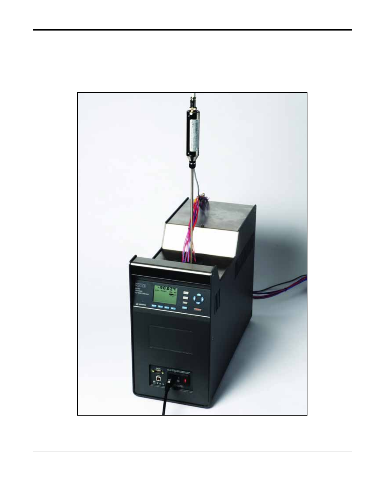
4.1.3 Constant Temperature Block. . . . . . . . . . . . . . . . . . . . . . . . . . . . . . . . . . . . . . . . . . . . . . . . . . . . . . . . . . . . . . . . . . . . . .15
4.1.4 Startup and Main Screen . . . . . . . . . . . . . . . . . . . . . . . . . . . . . . . . . . . . . . . . . . . . . . . . . . . . . . . . . . . . . . . . . . . . . . . . .16
4.2 Setting the Temperature . . . . . . . . . . . . . . . . . . . . . . . . . . . . . . . . . . . . . . . . . . . . . . . . . . . . . . . . . . . . . . . . . . . . . . . . . . . . . . .17
Chapter 5. General Operation
5.1 Calibrator Setup . . . . . . . . . . . . . . . . . . . . . . . . . . . . . . . . . . . . . . . . . . . . . . . . . . . . . . . . . . . . . . . . . . . . . . . . . . . . . . . . . . . . . . .19
5.2 Calibrating Sensors . . . . . . . . . . . . . . . . . . . . . . . . . . . . . . . . . . . . . . . . . . . . . . . . . . . . . . . . . . . . . . . . . . . . . . . . . . . . . . . . . . . .19
5.3 Insert Installation and Removal Procedure . . . . . . . . . . . . . . . . . . . . . . . . . . . . . . . . . . . . . . . . . . . . . . . . . . . . . . . . . . . . . .20
5.4 Probe Insertion and Removal Procedure . . . . . . . . . . . . . . . . . . . . . . . . . . . . . . . . . . . . . . . . . . . . . . . . . . . . . . . . . . . . . . . .22
Chapter 6. Calibrator Operation
6.1 Menus and Menu Navigation. . . . . . . . . . . . . . . . . . . . . . . . . . . . . . . . . . . . . . . . . . . . . . . . . . . . . . . . . . . . . . . . . . . . . . . . . . .25
6.1.1 Temperature Setup Menu (TEMP SETUP) . . . . . . . . . . . . . . . . . . . . . . . . . . . . . . . . . . . . . . . . . . . . . . . . . . . . . . . . . . .25
6.1.1a Temperature Setup . . . . . . . . . . . . . . . . . . . . . . . . . . . . . . . . . . . . . . . . . . . . . . . . . . . . . . . . . . . . . . . . . . . . . . . .26
6.1.1b Cutout . . . . . . . . . . . . . . . . . . . . . . . . . . . . . . . . . . . . . . . . . . . . . . . . . . . . . . . . . . . . . . . . . . . . . . . . . . . . . . . . . . . .27
6.1.1c Cooler Status . . . . . . . . . . . . . . . . . . . . . . . . . . . . . . . . . . . . . . . . . . . . . . . . . . . . . . . . . . . . . . . . . . . . . . . . . . . . . .28
6.1.2 Set Temperature . . . . . . . . . . . . . . . . . . . . . . . . . . . . . . . . . . . . . . . . . . . . . . . . . . . . . . . . . . . . . . . . . . . . . . . . . . . . . . . . .29
6.1.2a Set the Temperature SETPOINT Manually . . . . . . . . . . . . . . . . . . . . . . . . . . . . . . . . . . . . . . . . . . . . . . . . . . .29
6.1.2b Set the Temperature with a Preset SETPOINT. . . . . . . . . . . . . . . . . . . . . . . . . . . . . . . . . . . . . . . . . . . . . . . .30

Contents
iv Kaye LTR -90 Operating Manual
6.1.2c Change a Preset SETPOINT . . . . . . . . . . . . . . . . . . . . . . . . . . . . . . . . . . . . . . . . . . . . . . . . . . . . . . . . . . . . . . . . .30
6.1.3 Cancel or Stop Temperature Change . . . . . . . . . . . . . . . . . . . . . . . . . . . . . . . . . . . . . . . . . . . . . . . . . . . . . . . . . . . . . .30
6.1.4 Set a Soft Cutout . . . . . . . . . . . . . . . . . . . . . . . . . . . . . . . . . . . . . . . . . . . . . . . . . . . . . . . . . . . . . . . . . . . . . . . . . . . . . . . . .31
6.1.5 Reset an Over-Temperature Cutout . . . . . . . . . . . . . . . . . . . . . . . . . . . . . . . . . . . . . . . . . . . . . . . . . . . . . . . . . . . . . . .31
6.1.6 Programs (Automated Tests) . . . . . . . . . . . . . . . . . . . . . . . . . . . . . . . . . . . . . . . . . . . . . . . . . . . . . . . . . . . . . . . . . . . . . .32
6.1.6a Run a Program . . . . . . . . . . . . . . . . . . . . . . . . . . . . . . . . . . . . . . . . . . . . . . . . . . . . . . . . . . . . . . . . . . . . . . . . . . . .32
6.1.6b Stop a Program . . . . . . . . . . . . . . . . . . . . . . . . . . . . . . . . . . . . . . . . . . . . . . . . . . . . . . . . . . . . . . . . . . . . . . . . . . .32
6.1.7 Program Menu (PROG MENU) . . . . . . . . . . . . . . . . . . . . . . . . . . . . . . . . . . . . . . . . . . . . . . . . . . . . . . . . . . . . . . . . . . . . .33
6.1.7a Program Setup . . . . . . . . . . . . . . . . . . . . . . . . . . . . . . . . . . . . . . . . . . . . . . . . . . . . . . . . . . . . . . . . . . . . . . . . . . . .33
6.1.7b Ramp/Soak . . . . . . . . . . . . . . . . . . . . . . . . . . . . . . . . . . . . . . . . . . . . . . . . . . . . . . . . . . . . . . . . . . . . . . . . . . . . . . .34
6.1.8 System Menu (SYSTEM MENU) . . . . . . . . . . . . . . . . . . . . . . . . . . . . . . . . . . . . . . . . . . . . . . . . . . . . . . . . . . . . . . . . . . . .35
6.1.8a Display Setup . . . . . . . . . . . . . . . . . . . . . . . . . . . . . . . . . . . . . . . . . . . . . . . . . . . . . . . . . . . . . . . . . . . . . . . . . . . . .35
6.1.8b Communications Setup . . . . . . . . . . . . . . . . . . . . . . . . . . . . . . . . . . . . . . . . . . . . . . . . . . . . . . . . . . . . . . . . . . . .36
6.1.9 Calibration Setup Menu. . . . . . . . . . . . . . . . . . . . . . . . . . . . . . . . . . . . . . . . . . . . . . . . . . . . . . . . . . . . . . . . . . . . . . . . . . .36
6.1.9a System Information. . . . . . . . . . . . . . . . . . . . . . . . . . . . . . . . . . . . . . . . . . . . . . . . . . . . . . . . . . . . . . . . . . . . . . . .37
Chapter 7. Maintenance and Troubleshooting
7.1 Introduction. . . . . . . . . . . . . . . . . . . . . . . . . . . . . . . . . . . . . . . . . . . . . . . . . . . . . . . . . . . . . . . . . . . . . . . . . . . . . . . . . . . . . . . . . . .39
7.2 Maintenance. . . . . . . . . . . . . . . . . . . . . . . . . . . . . . . . . . . . . . . . . . . . . . . . . . . . . . . . . . . . . . . . . . . . . . . . . . . . . . . . . . . . . . . . . .39
7.2.1 Clean the Product . . . . . . . . . . . . . . . . . . . . . . . . . . . . . . . . . . . . . . . . . . . . . . . . . . . . . . . . . . . . . . . . . . . . . . . . . . . . . . . .39
7.2.2 Moisture Removal . . . . . . . . . . . . . . . . . . . . . . . . . . . . . . . . . . . . . . . . . . . . . . . . . . . . . . . . . . . . . . . . . . . . . . . . . . . . . . . .39
7.2.3 Clean the Insert . . . . . . . . . . . . . . . . . . . . . . . . . . . . . . . . . . . . . . . . . . . . . . . . . . . . . . . . . . . . . . . . . . . . . . . . . . . . . . . . . .39
7.2.4 Change the Fuse . . . . . . . . . . . . . . . . . . . . . . . . . . . . . . . . . . . . . . . . . . . . . . . . . . . . . . . . . . . . . . . . . . . . . . . . . . . . . . . . .40
7.3 Troubleshooting. . . . . . . . . . . . . . . . . . . . . . . . . . . . . . . . . . . . . . . . . . . . . . . . . . . . . . . . . . . . . . . . . . . . . . . . . . . . . . . . . . . . . . .41

Kaye LTR -90 Operating Manual 1
Chapter 1. Product Overview
The LTR -90 Ultra-Cool Dry Well Calibrator is a benchtop temperature calibrator that can calibrate precision
temperature instruments from-95°C to 140°C (see Figure 1 below).
Figure 1: LTR-90 Ultra-Cool Dry Well Calibrator

Chapter 1. Product Overview
2Kaye LTR -90 Operating Manual
1.1 Safety Information
WARNING! A Warning identifies conditions and procedures that are dangerous to the user.
CAUTION! A Caution identifies conditions and procedures that can cause damage to the product or the
equipment under test.
See Table 1 below for a list of symbols used in this manual and on the Calibrator.
WARNING! To prevent possible electrical shock, fire, or personal injury:
Read all safety Information before you use the Product.
Use the Product only as specified, or the protection supplied by the Product can be
compromised.
Use this Product indoors only.
Do not use the Product around explosive gas, vapor, or in damp or wet environments.
Do not use and disable the Product if it is damaged.
Use only the mains power cord and connector approved for the voltage and plug configuration
in your country and rated for the Product.
Replace the mains power cord if the insulation is damaged or if the insulation shows signs of
wear.
Table 1: Symbols
Symbol Description Symbol Description
Conforms to European
Union directives Conforms to relevant North American Safety
Standards.
Risk of Danger. Important
information. See manual. Conforms to relevant Australian EMC
requirements.
Earth ground Hazardous voltage
This product complies with the WEEE Directive (2002/96/EC) marking requirements.
The affixed label indicates that you must not discard this electrical/electronic product in
domestic household waste. Product Category: With reference to the equipment types in
the WEEE Directive Annex I, this product is classed as category 9 “Monitoring and
Control Instrumentation” product. Do not dispose of this product as unsorted municipal
waste.

Kaye LTR -90 Operating Manual 3
Chapter 1. Product Overview
WARNING! Make sure the ground conductor in the mains power cord is connected to a protective
earth ground. Disruption of the protective earth could put voltage on the chassis that could
cause death.
Do not put the Product where access to the mains power cord is blocked.
Use caution when you install and remove probes and inserts from the Product. They can be hot.
Do not touch voltages > 30 V ac rms, 42 V ac peak, or 60 V dc.
Do not apply more than the rated voltage, between the terminals or between each terminal and
earth ground.
Do not touch the well access surface of the instrument.
Do not turn off the product at block temperatures higher than 100°C. Select a SETPOINT less
than 100°C and let the instrument cool before turning it off.
Use the correct terminals, function, and range for measurements.
Do not use test leads if they are damaged. Examine the test leads for damaged insulation,
exposed metal, or if the wear indicator shows. Check test lead continuity.
Do not touch the probes to a voltage source when the test leads are connected to the current
terminals.
Keep fingers behind the finger guards on the probes.
Do not exceed the Measurement Category (CAT) rating of the lowest rated individual component
of a Product, probe, or accessory.

Chapter 1. Product Overview
4Kaye LTR -90 Operating Manual
1.2 Contact Amphenol Advanced Sensors Customer Service
You may contact our North American customer service team at 814-834-9140 (fax: 814-781-7969). You may also call
our European headquarters in Germany at +49 (0) 7231-14335 0.
1.3 Calibration and Repair Information
To schedule and send the Calibrator to Amphenol Advanced Sensors for calibration or repair:
1. Contact the Amphenol Advanced Sensors Service Center in your area to schedule the calibration or repair.
2. Pack and secure the Calibrator in a shipment box with a minimum of 2 inches of packing around the Calibrator to
prevent damage.
3. Send the Calibrator to the Service Center.

Kaye LTR -90 Operating Manual 5
Chapter 2. Specifications
2.1 Introduction
The Ultra Cool Dry Calibrator (LTR-90) provides a stable, portable temperature reference for performing
thermocouple calibration. The LTR-90 operates over the range of -95°C to 140°C.
The LTR-90 is most commonly used with Kaye's Intelligent RTD (IRTD) probe and Kaye Validator to make up a
complete validation system. The LTR-90 has the ability to rapidly heat and cool, making it an ideal instrument for
performing multiple-point calibrations for a variety of processes, such as freeze dryer, cold rooms, incubators and
steam sterilizers.
The LTR-90 has 4 wells for sensors and two wells for IRTD probes. For calibrating thermocouples, there are inserts
that go into each well to reduce stem conduction errors, thereby providing maximum accuracy and stability. With
inserts installed, each of the 4 sensor wells can hold three 22 gauge PTFE thermocouples, for a total of 12
thermocouples. Utilizing smaller gauge thermocouples can expand calibration capacity.
The Kaye Validator automatically performs the sensor calibration, including programming the set-point temperatures at
the LTR-90. If you are using the LTR-90 as a standalone instrument, the temperatures can be manually set to any
temperature within the specified range by using the control buttons located on the front panel.
These dry-well calibrators are designed for portability, moderate cost, and ease of operation. With proper use they
should provide continued accurate calibration of temperature sensors and devices. The user should be familiar with the
safety guidelines and operating procedures of the calibrator as described in this Operator's Manual.

Chapter 2. Specifications
6Kaye LTR -90 Operating Manual
2.2 Specifications
The following section lists the specifications for this instrument. Accuracy specifications are applicable for a one-year
calibration interval.
2.2.1 Base Unit Specifications
Part Numbers and Descriptions
Temperature Range at 23°C
-95°C to 140°C (-139°F to 284°F)
Display Accuracy
±0.2°C Full Range
Stability
±0.015°C Full Range
Loading Effect
(with a 6.35 mm reference probe and three 6.35 mm probes)
±0.006°C Full Range
(versus display with 6.35 mm probes)
±0.25°C at -95°C
±0.10°C at 140°C
Operating Conditions
0°C to 35°C, 0% to 90%
RH (non-condensing) < 2000 m altitude
Environmental conditions for all specifications except temperature range
13°C to 33°C
Immersion (Well) Depth
160 mm (6.3 in)
Well Diameter
30 mm (1.18 in)
Sleeve Hole Diameter
X0395 LTR -90 Low Temperature Dry Well -95° to 140°C, (115Volts, 60Hz)
X0395CE LTR -90 Low Temperature Dry Well --95° to 140°C , (230Volts, 50Hz)
X0395JP LTR -90 Low Temperature Dry Well -95° to 140°C, (115Volts, 50/60Hz)
X0395AS LTR -90 Low Temperature Dry Well -95° to 140°C (230Volts, 50/60Hz)

Kaye LTR -90 Operating Manual 7
Chapter 2. Specifications
IRTD hole: 6.7 mm (0.265 in)
Sensor hole: 9 mm (0.354 in)
Heating Time [1]
-95°C to 140°C: 40 min
Cooling Time [1]
23°C to -90°C: 80 min
23°C to -95°C: 90 min
140°C to 23°C: 60 min
Stabilization Time [2]
15 min
Resolution
0.01°
Display
LCD, °C or °F user selectable
Size (H x W x D)
480 mm x 205 mm x 380 mm (18.8 in x 8.0 in x 14.9 in)
Weight
16 kg (35 lb)
Power Requirements
100 V to 115 V (±10%) 50/60 Hz, 575 W (X0395, X0395JP)
200 V to 230 V (±10%) 50/60 Hz, 575 W (X0395CE, X0395AS)
System Fuse Ratings
115 V: 6.3 A T 250 V (Kaye part #:193-100)
230 V: 3.15 A T 250 V (Kaye part#: 193-099)
Safety
IEC 61010-1, Installation Category II, Pollution degree 2
Electromagnetic Environment
IEC 61326-1: Basic
Refrigerants
R32 (Difluoromethane) < 20 g, ASHRAE Safety Group A2L
R704 (Helium) < 20 g, ASHRAE Safety Group A1
Notes:
[1] — For ambient temperature of 23°C.
[2] —Time from when the SETPOINT is reached to when the unit is within Stability specification.

Chapter 2. Specifications
8Kaye LTR -90 Operating Manual
[no content intended for this page]

Kaye LTR -90 Operating Manual 9
Chapter 3. Quick Start
3.1 Unpack and Inspect
Unpack the instrument carefully and examine it for any damage that could have occurred during shipment. If there is
shipping damage, notify Amphenol Advanced Sensors Customer Service and the carrier immediately. Table 2 lists the
equipment and the accessories that comes with the Calibrator. Verify that all the equipment and accessories in Table 6
are in the box.
3.2 Placement
Put the Calibrator on a clean, flat surface. Make sure the Calibrator is 150 mm (6 inches) away from all objects. For
best results, choose a location to set up the product where room temperature changes are minimal.
WARNING! To prevent possible fire or personal injury:
Do not operate the LTR -90 in orientations other than upright. A fire hazard can be made if the
LTR -90 is put on its side.
Do not remove Inserts when the product shows temperatures more than 50 °C.
Do not operate near flammable materials.
Do not touch the well access surface of the Product.
Do not turn off the LTR -90 when the temperature is above 100 °C. Set a SETPOINT temperature
below 100 °C and let the LTR -90 cool.
Table 2: Parts and Accessories
Name Quantity
LTR -90 1
2-meter (6-foot) Mains Power Cord 1
Certificate of Calibration 1
Insert Removal Tool 1
Well Insulator Cap 1
Temperature Reference to Communication Interface cable 1
Four extruded sleeves (for Thermocouples) 1
Calibration block (with 6 wells) 1

Chapter 3. Quick Start
10 Kaye LTR -90 Operating Manual
3.2 Placement (cont.)
CAUTION! For safe operation and maintenance of the Product:
Energize the LTR -90 for a 2-hour dry-out period before use, if the LTR -90 was:
In transport
In a humid or semi-humid storage environment
Not energized for more than 10 days
If the product is wet or has been in a wet environment, take necessary measures to remove
moisture prior to applying power.
Always operate the LTR -90 on a flat, level, stable surface.
Do not store the LTR -90 at temperatures above 50 °C. The product has a refrigeration system
and contains gasses under pressure.
Do not turn the Product upside down. The inserts will fall out.
To prevent damage to the cooling system, do not tilt the LTR -90 on its side or upside down while
the LTR -90 is operating.
3.3 Connect to Mains Power
Use the 2-meter (6-foot) mains power cord to connect the Product to a 120 V ac or 230 V ac outlet rated for at least 10
amps.
3.4 Turn On the Product
1. Push the “I” side of the power switch on the front panel of the Calibrator.
2. Monitor the Startup screen for errors while the product turns on. If an error shows, contact Amphenol Advanced
Sensors Customer Service.
3.5 Change Language
To change the display language:
1. Push .
2. Push .
3. Push .
4. Push .
5. Push or to highlight a language.
6. Push to set language.

Kaye LTR -90 Operating Manual 11
Chapter 3. Quick Start
Note: If the incorrect language is set by accident, push softkeys and at the same time to temporarily
switch back to the English language.
3.6 Set Display Contrast
With the Main screen shown in the display, push to increase or push to decrease display contrast.
3.7 Toggle Key Beep On or Off
With the Main screen shown in the display, push and at the same time to enable or disable key beep.
3.8 Security and Password
The Calibrator has two user-level access security levels (Low and High) to protect from undesired changes to the
settings (see Table 3 below). The Calibrator comes from the factory with the security level set to High and a default
password of “1234”.
If the password is not available, the information can still be viewed. To view the information without the password,
push twice or push when prompted for the password. The information is then shown on the screen, but
cannot be changed.
Note: The Calibrator does not have a password reset function. If the password is lost, contact Amphenol Advanced
Sensors Customer Service for password reset assistance.
To change the password:
1. Push .
2. Push .
3. Push .
4. Enter the current 4-digit password to open the password screen (the default factory password is 1234).
5. Push and to highlight a digit, then push to increase the digit or push to decrease the digit.
6. Push to save the password.
To change the security level:
1. Push .
2. Push .
3. Push .
4. Enter the current 4-digit password to open the password screen (the default factory password is 1234).
Table 3: Security Levels
Security Level Definition
Low Protects the specific metrological information and calibration information settings.
High Protects all operating parameters. It is intended to minimize user choices, for
example, to perform repeated identical calibrations under consistent conditions.

Chapter 3. Quick Start
12 Kaye LTR -90 Operating Manual
[no content intended for this page]
5. Push and to highlight HIGH or LOW.
6. Push to save the selection.

Kaye LTR -90 Operating Manual 13
Chapter 4. Parts and Controls
4.1 Calibrator Features
Table 4 identifies and describes the panels on the front of the Calibrator.
Figure 2: The LTR -90 Front Panel
Table 4: LTR -90 Front Panel
Item Name Function
1 Display and Control Panel Control panel and display. See “Display and Control Panel” on the
next page.
2 Power and Remote Interface Panel Power module and Remote Interface Panel. See “Power and Remote
Interface Panel” on page 15.
1
2

Chapter 4. Parts and Controls
14 Kaye LTR -90 Operating Manual
4.1.1 Display and Control Panel
Table 5 shows and describes the function of each button on the Control Panel.
Figure 3: Display and Control Panel
Table 5: Display and Control Panel
Item Name Function
1 Display Shows block temperature, measurements, status information, operating parameters,
and softkey functions. The contrast of the display is adjustable. To adjust the contrast,
push to increase contrast orto decrease contrast while the Main screen is shown.
2ArrowKeys
Navigates through menu selections, increases or decreases numbers, and scrolls menus
up or down.
3Enter Key Selects menus and sets new values.
4 SET Point Key Set a SETPOINT temperature to heat or cool to.
5 °C/°F Key Switches the displayed temperature unitsbetween °C and °F. Key is enabled only when
the Main screen is shown.
6 Menu Key Opens the Main menu. See “Menus and Menu Navigation” on page 25 for information
on each menu and the settings found in the menus.
7Exit Key Cancels all changes and navigates back to the previous menu.
8 Softkeys Navigates the menus on the display. The functions of the softkeys are shown on the
display above the buttons.
9 Block Temperature
Indicator
Visual safety indicator that illuminates when the block temperature is unsafe and
extinguishes when the block temperature is safe. If the block temperature is unsafe and
the Calibrator is turned off or the mains power cord is disconnected, the indicator
flashes until the block temperature cools to a safe temperature. Do not transport or
remove Inserts until the indicator is off.
WARNING! For safe operation and maintenance of the product, do not remove
Inserts when the Block Temperature indicator is illuminated.
12
3
4
5
6
7
8
9
This manual suits for next models
4
Table of contents
Other Kaye Test Equipment manuals