Pfeiffer Vacuum OPS 100 User manual

OPERATING INSTRUCTIONS
EN
Translation of the Original
OPS 100
On-board power supply pack

Dear Customer,
Thank you for choosing a Pfeiffer Vacuum product. Your new power supply pack is designed
to support you in your individual application with full performance and without malfunctions.
The name Pfeiffer Vacuum stands for high-quality vacuum technology, a comprehensive and
complete range of top-quality products and first-class service. From this extensive, practical
experience we have gained a large volume of information that can contribute to efficient
deployment and to your personal safety.
In the knowledge that our product must avoid consuming work output, we trust that our
product can offer you a solution that supports you in the effective and trouble-free
implementation of your individual application.
Please read these operating instructions before putting your product into operation for the
first time. If you have any questions or suggestions, please feel free to contact info@pfeiffer-
vacuum.de.
Further operating instructions from Pfeiffer Vacuum can be found in the Download Center on
our website.
Disclaimer of liability
These operating instructions describe all models and variants of your product. Note that your
product may not be equipped with all features described in this document. Pfeiffer Vacuum
constantly adapts its products to the latest state of the art without prior notice. Please take
into account that online operating instructions can deviate from the printed operating
instructions supplied with your product.
Furthermore, Pfeiffer Vacuum assumes no responsibility or liability for damage resulting from
the use of the product that contradicts its proper use or is explicitly defined as foreseeable
misuse.
Copyright
This document is the intellectual property of Pfeiffer Vacuum and all contents of this
document are protected by copyright. They may not be copied, altered, reproduced or
published without the prior written permission of Pfeiffer Vacuum.
We reserve the right to make changes to the technical data and information in this document.
2/28

Table of contents
1 About this manual 6
1.1 Validity 6
1.1.1 Applicable documents 6
1.1.2 Variants 6
1.2 Target group 6
1.3 Conventions 6
1.3.1 Instructions in the text 6
1.3.2 Pictographs 6
1.3.3 Stickers on the product 7
1.3.4 Abbreviations 7
2 Safety 8
2.1 General safety information 8
2.2 Safety instructions 8
2.3 Safety precautions 10
2.4 Limits of use of the product 10
2.5 Proper use 10
2.6 Foreseeable misuse 10
2.7 Personnel qualification 11
2.7.1 Ensuring personnel qualification 11
2.7.2 Personnel qualification for maintenance and repair 11
2.7.3 Advanced training with Pfeiffer Vacuum 12
3 Product description 13
3.1 Function 13
3.2 Identifying the product 13
3.3 Connections 13
3.4 Scope of delivery 13
4 Installation 14
4.1 Preparing for installation 14
4.2 Connection diagram 14
4.3 Establishing the electric connection 15
5 Operation 16
5.1 Switching on 16
5.2 Switching off 16
6 Maintenance 17
6.1 Dismantling the power supply pack 17
6.2 Installing the power supply pack 18
7 Recycling and disposal 19
7.1 General disposal information 19
7.2 Disposing of the power supply pack 19
8 Malfunctions 20
9 Service solutions by Pfeiffer Vacuum 21
10 Spare parts 23
11 Accessories 24
12 Technical data and dimensions 25
12.1 Technical data 25
12.2 Dimensions 25
Declaration of conformity 26
Table of contents
3/28

List of figures
Fig. 1: Position of the stickers on the product 7
Fig. 2: OPS 100 layout 13
Fig. 3: Connection diagram for HiPace 300 with TC 110 and OPS 100 14
Fig. 4: Mains connection 15
Fig. 5: Dismantling the OPS 100 from the HiPace 300 17
Fig. 6: Mounting of OPS 100 onto HiPace 300 18
Fig. 7: Spare parts for OPS 100 23
Fig. 8: Dimensions OPS 100 25
List of figures
5/28

1 About this manual
IMPORTANT
Read carefully before use.
Keep the manual for future consultation.
1.1 Validity
This operating instructions is a customer document of Pfeiffer Vacuum. The operating instructions de-
scribe the functions of the named product and provide the most important information for the safe use of
the device. The description is written in accordance with the valid directives. The information in this op-
erating instructions refers to the product's current development status. The document shall remain valid
provided that the customer does not make any changes to the product.
1.1.1 Applicable documents
Designation Number
Declaration of conformity A component of these instructions
1.1.2 Variants
This instruction applies for power supply packs with the following type designation:
●OPS 100
1.2 Target group
These operating instructions are aimed at all persons performing the following activities on the product:
●Transportation
●Setup (Installation)
●Usage and operation
●Decommissioning
●Maintenance and cleaning
●Storage or disposal
The work described in this document is only permitted to be performed by persons with the appropriate
technical qualifications (expert personnel) or who have received the relevant training from Pfeiffer Vac-
uum.
1.3 Conventions
1.3.1 Instructions in the text
Usage instructions in the document follow a general structure that is complete in itself. The required ac-
tion is indicated by an individual step or multi-part action steps.
Individual action step
A horizontal, solid triangle indicates the only step in an action.
►This is an individual action step.
Sequence of multi-part action steps
The numerical list indicates an action with multiple necessary steps.
1. Step 1
2. Step 2
3. ...
1.3.2 Pictographs
Pictographs used in the document indicate useful information.
About this manual
6/28

Note
Tip
1.3.3 Stickers on the product
This section describes all the stickers on the product along with their meaning.
Mod.:
Mod.-No.:
Input:
Output:
Ser. -No.:
Made in Germany
OPS 100
PM 061 680 -X
Weight:
115-230 V 50/60 Hz 120 VA
D-35614 Asslar
24 V 4.16 A
1.0 kg 2020
75017003
Rating plate (example)
Rating plates of the devices are affixed to the housing where
they can be clearly seen
CUS
Safety approved
USA CAN
TÜV Rheinland
Test seal:
The test seal provides information regarding additional certifi-
cations
Tbl. 1: Stickers on the product
2
1
Fig. 1: Position of the stickers on the product
1 Rating plate 2 CAN/USA test seal
1.3.4 Abbreviations
Abbreviation Meaning in this document
AC Alternating Current
DC Direct Current
PE Earthed conductor (protective earth)
TC Turbopump electronic drive unit (turbo controller)
OPS On-board power supply pack
Tbl. 2: Abbreviations used in this document
About this manual
7/28

2 Safety
2.1 General safety information
The following 4 risk levels and 1 information level are taken into account in this document.
DANGER
Immediately pending danger
Indicates an immediately pending danger that will result in death or serious injury if not observed.
►Instructions to avoid the danger situation
WARNING
Potential pending danger
Indicates a pending danger that could result in death or serious injury if not observed.
►Instructions to avoid the danger situation
CAUTION
Potential pending danger
Indicates a pending danger that could result in minor injuries if not observed.
►Instructions to avoid the danger situation
NOTICE
Danger of damage to property
Is used to highlight actions that are not associated with personal injury.
►Instructions to avoid damage to property
Notes, tips or examples indicate important information about the product or about this docu-
ment.
2.2 Safety instructions
All safety instructions in this document are based on the results of the risk assessment carried out in
accordance with Low Voltage Directive 2014/35/EU. Where applicable, all life cycle phases of the prod-
uct were taken into account.
Risks during installation
WARNING
Risk of fatal injury due to electric shock on account of incorrect installation
The device's power supply uses life-threatening voltages. Unsafe or improper installation can lead to
life-threatening situations from electric shocks obtained from working with or on the unit.
►Ensure safe integration into an emergency off safety circuit.
►Do not carry out your own conversions or modifications on the unit.
WARNING
Danger of cut injuries from unexpected start up.
The use of mating plugs of the electronic drive unit (accessories) enables the automatic run-up of the
vacuum pump as soon the power is turned on. Attaching mating plugs before or during the installa-
tion leads to the movement of parts hence the risk of cut injuries by sharp-edged in the exposed high
vacuum flange.
►Only connect mating plugs after the mechanical installation.
►Only switch on the vacuum pump immediately prior to operation.
Safety
8/28

WARNING
Risk of danger to life through missing mains disconnection device
The vacuum pump and electronic drive unit are not equipped with a mains disconnection device
(mains switch).
►Install a mains disconnection device according to SEMI-S2.
►Install a circuit breaker with an interruption rating of at least 10,000 A.
Risks during operation
WARNING
Danger of cut injuries from unexpected start up.
The use of mating plugs of the electronic drive unit (accessories) enables the automatic run-up of the
vacuum pump as soon the power is turned on. Attaching mating plugs before or during the installa-
tion leads to the movement of parts hence the risk of cut injuries by sharp-edged in the exposed high
vacuum flange.
►Only connect mating plugs after the mechanical installation.
►Only switch on the vacuum pump immediately prior to operation.
WARNING
Risk of burns in case of contact with hot surfaces
For the operator's safety, the products are designed to avoid thermal risk. Depending on the applica-
tion, the conditions of use generate high temperatures which require extra caution from users (surfa-
ces > 65 °C).
►Pay attention to the marking of hot surfaces indicated by safety labels.
►Wait for the part to cool completely before working on the product.
►If necessary, wear protective gloves in accordance with standard EN 420.
Risks during maintenance
WARNING
Danger to life from electric shock during maintenance and service work
The device is only completely de-energized when the mains plug has been disconnected and the
vacuum pump is at a standstill. There is a danger to life from electric shock when making contact with
live components.
►Before performing all work, switch off the main switch.
►Wait until the vacuum pump comes to a standstill (rotation speed =0).
►Disconnect all connection cables.
►Remove the mains plug from the device.
►Secure the device against unintentional restarting.
Recycling and disposal
WARNING
Health hazard through poisoning from toxic contaminated components or devices
Toxic process media result in contamination of devices or parts of them. During maintenance work,
there is a risk to health from contact with these poisonous substances. Illegal disposal of toxic sub-
stances causes environmental damage.
►Take suitable safety precautions and prevent health hazards or environmental pollution by toxic
process media.
►Decontaminate affected parts before carrying out maintenance work.
►Wear protective equipment.
Safety
9/28

Risks during troubleshooting
WARNING
Danger to life from electric shock in the event of a fault
In the event of a fault, devices connected to the mains may be live. There is a danger to life from
electric shock when making contact with live components.
►Always keep the mains connection freely accessible so you can disconnect it at any time.
2.3 Safety precautions
Duty to provide information on potential dangers
The product holder or user is obliged to make all operating personnel aware of dangers
posed by this product.
Every person who is involved in the installation, operation or maintenance of the product
must read, understand and adhere to the safety-related parts of this document.
Infringement of conformity due to modifications to the product
The Declaration of Conformity from the manufacturer is no longer valid if the operator
changes the original product or installs additional equipment.
●Following the installation into a system, the operator is required to check and re-evalu-
ate the conformity of the overall system in the context of the relevant European Direc-
tives, before commissioning that system.
General safety precautions when handling the product
►Use only power supply packs that comply with the applicable safety regulations.
►Observe all applicable safety and accident prevention regulations.
►Check that all safety measures are observed at regular intervals.
►Recommendation: Establish a secure connection to the earthed conductor (PE); protection class I.
►Never disconnect plug connections during operation.
►Keep lines and cables away from hot surfaces (> 70 °C).
►Do not carry out your own conversions or modifications on the unit.
►Observe the unit protection class prior to installation or operation in other environments.
2.4 Limits of use of the product
Installation location weatherproof (internal space)
Air pressure 750 hPa to 1060 hPa
Installation altitude max. 2000 m
Rel. air humidity max. 80%, at T < 31°C,
up to max. 50% at T < 40°C
Protection class I
Protection category IP20
Ambient temperature +5 ° to +50 °C
Tbl. 3: Permissible ambient conditions
2.5 Proper use
●The power supply packs are used exclusively to provide a voltage supply to the electronic drive
units of Pfeiffer Vacuum vacuum pumps and their accessories.
2.6 Foreseeable misuse
Improper use of the product invalidates all warranty and liability claims. Any use that is counter to the
purpose of the product, whether intentional or unintentional, is regarded as misuse, in particular:
Safety
10/28

●Connection to the current supply that do not comply with the provisions of IEC 61010 or IEC
60950
●Operation with excessively high irradiated heat output
●Use in areas with ionizing radiation
●Operation in explosion-hazard areas
●Use of accessories or spare parts that are not listed in these instructions
2.7 Personnel qualification
The work described in this document may only be carried out by persons who have appropriate profes-
sional qualifications and the necessary experience or who have completed the necessary training as
provided by Pfeiffer Vacuum.
Training people
1. Train the technical personnel on the product.
2. Only let personnel to be trained work with and on the product when under the supervision of
trained personnel.
3. Only allow trained technical personnel to work with the product.
4. Before starting work, make sure that the commissioned personnel have read and understood
these operating instructions and all applicable documents, in particular the safety, maintenance
and repair information.
2.7.1 Ensuring personnel qualification
Specialist for mechanical work
Only a trained specialist may carry out mechanical work. Within the meaning of this document, special-
ists are people responsible for construction, mechanical installation, troubleshooting and maintenance
of the product, and who have the following qualifications:
●Qualification in the mechanical field in accordance with nationally applicable regulations
●Knowledge of this documentation
Specialist for electrotechnical work
Only a trained electrician may carry out electrical engineering work. Within the meaning of this docu-
ment, electricians are people responsible for electrical installation, commissioning, troubleshooting, and
maintenance of the product, and who have the following qualifications:
●Qualification in the electrical engineering field in accordance with nationally applicable regulations
●Knowledge of this documentation
In addition, these individuals must be familiar with applicable safety regulations and laws, as well as the
other standards, guidelines, and laws referred to in this documentation. The above individuals must
have an explicitly granted operational authorization to commission, program, configure, mark, and earth
devices, systems, and circuits in accordance with safety technology standards.
Trained individuals
Only adequately trained individuals may carry out all works in other transport, storage, operation and
disposal fields. Such training must ensure that individuals are capable of carrying out the required activi-
ties and work steps safely and properly.
2.7.2 Personnel qualification for maintenance and repair
Advanced training courses
Pfeiffer Vacuum offers advanced training courses to maintenance levels 2 and 3.
Adequately trained individuals are:
Safety
11/28

●Maintenance level 1
─Customer (trained specialist)
●Maintenance level 2
─Customer with technical education
─Pfeiffer Vacuum service technician
●Maintenance level 3
─Customer with Pfeiffer Vacuum service training
─Pfeiffer Vacuum service technician
2.7.3 Advanced training with Pfeiffer Vacuum
For optimal and trouble-free use of this product, Pfeiffer Vacuum offers a comprehensive range of
courses and technical trainings.
For more information, please contact Pfeiffer Vacuum technical training.
Safety
12/28

3 Product description
3.1 Function
OPS-type power supply packs are used exclusively to provide an on-board voltage supply to the elec-
tronic drive unit of Pfeiffer Vacuum vacuum pumps. The output voltage "DC out" is safely isolated from
the mains input voltage "AC in".
Bridges are installed ex factory in the power supply plug of the OPS to ensure that the pump starts up
immediately following connection of the mains voltage.
1
2
3
4
Fig. 2: OPS 100 layout
1 OPS 100 3 Power supply plug
2 Electronic drive unit TC 110 4 Turbopump HiPace 300
3.2 Identifying the product
►To ensure clear identification of the product when communicating with Pfeiffer Vacuum, always
keep all of the information on the rating plate to hand.
►Learn about certifications through test seals on the product or at www.certipedia.com with compa-
ny ID no. 000024550.
3.3 Connections
AC in
Mains connection socket (IEC 320 C14)
X3
D-Sub socket with 15 pins for the voltage supply.
Tbl. 4: Connection description for OPS 100
3.4 Scope of delivery
●Power supply pack OPS
●Fixing materials
●Operating instructions
Product description
13/28

4 Installation
4.1 Preparing for installation
General comments regarding installation
►Choose a site for installation where access to the product and to supply lines is possible at all
times.
►Respect the ambient conditions stated for the area of use.
►Only use the fixing holes provided.
►Never operate the power supply pack separately from the turbopump.
►Ensure that the cooling surface of the power supply pack is securely connected with the bottom
part of the turbopump.
4.2 Connection diagram
Bridges are installed ex factory in the power supply plug of the OPS.
Automatic start
The turbopump starts up immediately on bridging the pin 2, 5, 7 contacts on the "X3" con-
nection or using the a connection cable "with bridges" and running the supply voltage.
2
3
4
5
6
7
10
11
8
9
12
13
14
15
1
X3
TC 110
DI Remote
DI1
DI2
DI PumpgStatn
DI Standby
24 V DC* (V+)
ACC A1
ACC B1
DO1
DO2
AO1
RS 485 D+
RS 485 D-
+U
B
FE
2
3
4
5
6
7
10
11
8
9
12
13
14
15
1
S2
S1
+U
B
PE
90 - 132 /
185 - 265 V AC
2
1
3
OPS 100
Fig. 3: Connection diagram for HiPace 300 with TC 110 and OPS 100
Installation
14/28

4.3 Establishing the electric connection
WARNING
Risk of fatal injury due to electric shock on account of incorrect installation
The device's power supply uses life-threatening voltages. Unsafe or improper installation can lead to
life-threatening situations from electric shocks obtained from working with or on the unit.
►Ensure safe integration into an emergency off safety circuit.
►Do not carry out your own conversions or modifications on the unit.
WARNING
Danger of cut injuries from unexpected start up.
The use of mating plugs of the electronic drive unit (accessories) enables the automatic run-up of the
vacuum pump as soon the power is turned on. Attaching mating plugs before or during the installa-
tion leads to the movement of parts hence the risk of cut injuries by sharp-edged in the exposed high
vacuum flange.
►Only connect mating plugs after the mechanical installation.
►Only switch on the vacuum pump immediately prior to operation.
WARNING
Risk of danger to life through missing mains disconnection device
The vacuum pump and electronic drive unit are not equipped with a mains disconnection device
(mains switch).
►Install a mains disconnection device according to SEMI-S2.
►Install a circuit breaker with an interruption rating of at least 10,000 A.
3
2
1
Fig. 4: Mains connection
1 Power supply pack OPS 100 2 Mains cable with bushing
Connecting to the mains power supply
►Make sure that the supply voltage is correct.
►Order a corresponding power supply cable from the Pfeiffer Vacuum accessories range.
►Plug the mains connection cable into the "AC in" power supply plug.
►Secure the connection with the mounting bracket.
►Always ensure a secure connection to the earthed conductor (PE), protection class I.
Installation
15/28

5 Operation
5.1 Switching on
WARNING
Danger of cut injuries from unexpected start up.
The use of mating plugs of the electronic drive unit (accessories) enables the automatic run-up of the
vacuum pump as soon the power is turned on. Attaching mating plugs before or during the installa-
tion leads to the movement of parts hence the risk of cut injuries by sharp-edged in the exposed high
vacuum flange.
►Only connect mating plugs after the mechanical installation.
►Only switch on the vacuum pump immediately prior to operation.
WARNING
Risk of burns in case of contact with hot surfaces
For the operator's safety, the products are designed to avoid thermal risk. Depending on the applica-
tion, the conditions of use generate high temperatures which require extra caution from users (surfa-
ces > 65 °C).
►Pay attention to the marking of hot surfaces indicated by safety labels.
►Wait for the part to cool completely before working on the product.
►If necessary, wear protective gloves in accordance with standard EN 420.
Procedure
1. Connect the mains cable to the customer's mains power supply.
2. Switch on the mains power supply.
After applying the operating voltage, the electronic drive unit carries out a self-test to check the supply
voltage. After completing the self-test successfully, the turbopump starts and activates connected addi-
tional equipment according to the configuration.
5.2 Switching off
Procedure
1. Disconnect the power supply pack from the mains to disconnect the current supply completely.
Operation
16/28

6 Maintenance
WARNING
Danger to life from electric shock during maintenance and service work
The device is only completely de-energized when the mains plug has been disconnected and the
vacuum pump is at a standstill. There is a danger to life from electric shock when making contact with
live components.
►Before performing all work, switch off the main switch.
►Wait until the vacuum pump comes to a standstill (rotation speed =0).
►Disconnect all connection cables.
►Remove the mains plug from the device.
►Secure the device against unintentional restarting.
The power supply pack cannot be repaired. Replacement of the on-board power supply pack is essen-
tially the same procedure for all specified pump types.
Prerequisites
●Turbopump is off.
●The vacuum system is vented to atmospheric pressure.
●The electrical supply is disconnected.
Approach in case of a defect
►In case of a defect, replace the entire device.
6.1 Dismantling the power supply pack
Required aids
●Original protective cover
Required tools
●Allen key, WAF 6
1
5
23
4
Fig. 5: Dismantling the OPS 100 from the HiPace 300
1 Power supply plug 4 Mains connection with mounting bracket
2 OPS 100 Power supply unit 5 Electronic drive unit
3 Interior hexagon socket screw
Procedure
1. Remove the turbopump from the system if necessary.
2. Seal all connections with the original protective cover.
3. Place the turbopump on the closed high vacuum flange.
4. Disconnect the power supply plug from the TC.
Maintenance
17/28

5. Unscrew both interior hexagon socket screws from the power supply pack.
6. Remove the power supply pack from the turbopump.
6.2 Installing the power supply pack
Required aids
●Original protective cover
Required tools
●Allen key, WAF 6
1
4
23
5
Fig. 6: Mounting of OPS 100 onto HiPace 300
1 OPS 100 Power supply unit 4 Electronic drive unit
2 Interior hexagon socket screw 5 Mains connection with mounting bracket
3 Power supply plug
Procedure
1. Seal all connections with the original protective cover.
2. Place the turbopump on the closed high vacuum flange.
3. Secure the OPS 100 at the threaded holes provided on the bottom part of the turbopump.
4. Connect the connecting cable to the 15-pin D-sub socket on the electronic drive unit.
5. Connect the mains cable with the "AC in" connection of the OPS power supply pack.
6. Connect the mounting bracket of the connecting plug.
Maintenance
18/28

7 Recycling and disposal
WARNING
Health hazard through poisoning from toxic contaminated components or devices
Toxic process media result in contamination of devices or parts of them. During maintenance work,
there is a risk to health from contact with these poisonous substances. Illegal disposal of toxic sub-
stances causes environmental damage.
►Take suitable safety precautions and prevent health hazards or environmental pollution by toxic
process media.
►Decontaminate affected parts before carrying out maintenance work.
►Wear protective equipment.
Environmental protection
You must dispose of the product and its components in accordance with all applicable reg-
ulations for protecting people, the environment and nature.
●Help to reduce the wastage of natural resources.
●Prevent contamination.
Environmental protection
The product and its components must be disposed of in accordance with the applica-
ble regulations relating to environmental protection and human health, with a view to
reducing natural resource wastage and preventing pollution.
7.1 General disposal information
Pfeiffer Vacuum products contain materials that you must recycle.
►Dispose of our products according to the following:
–Iron
–Aluminium
–Copper
–Synthetic
–Electronic components
–Oil and fat, solvent-free
►Observe the special precautionary measures when disposing of:
–Fluoroelastomers (FKM)
–Potentially contaminated components that come into contact with media
7.2 Disposing of the power supply pack
Electronic components and their housings contain material that must be recycled.
►Dispose of electronic components in a safe manner according to locally applicable regulations.
Recycling and disposal
19/28

8 Malfunctions
WARNING
Danger to life from electric shock in the event of a fault
In the event of a fault, devices connected to the mains may be live. There is a danger to life from
electric shock when making contact with live components.
►Always keep the mains connection freely accessible so you can disconnect it at any time.
Malfunctions
20/28
Table of contents
Other Pfeiffer Vacuum Controllers manuals
Pfeiffer Vacuum
Pfeiffer Vacuum IMG 400 User manual
Pfeiffer Vacuum
Pfeiffer Vacuum TCP 600 User manual
Pfeiffer Vacuum
Pfeiffer Vacuum TPS 110 User manual
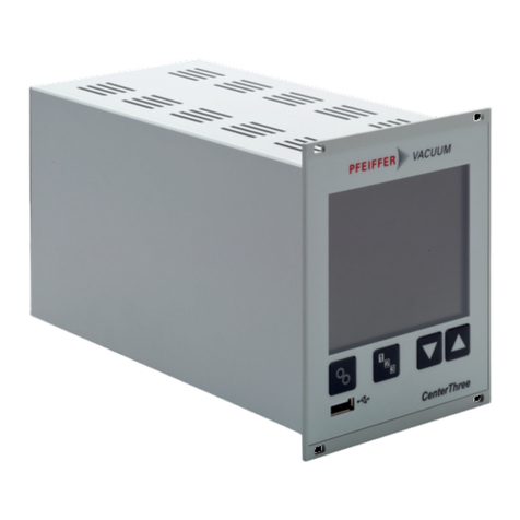
Pfeiffer Vacuum
Pfeiffer Vacuum CenterOne User manual

Pfeiffer Vacuum
Pfeiffer Vacuum Tele TC cable 110 User manual

Pfeiffer Vacuum
Pfeiffer Vacuum MaxiGauge TPG 256 A PT G28 760 User manual
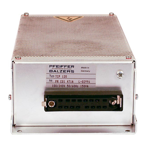
Pfeiffer Vacuum
Pfeiffer Vacuum TCP 120 User manual
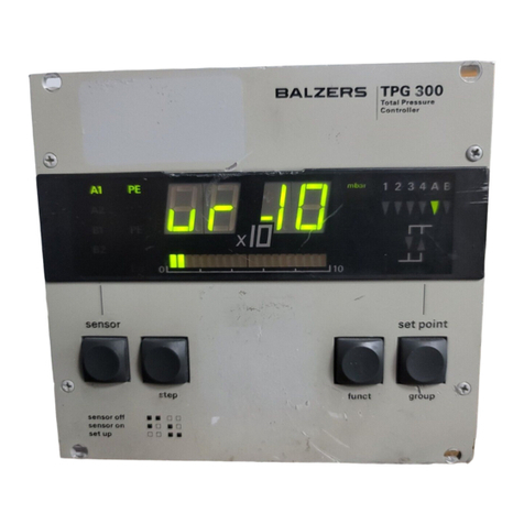
Pfeiffer Vacuum
Pfeiffer Vacuum TPG 300 User manual

Pfeiffer Vacuum
Pfeiffer Vacuum DPG 109 User manual
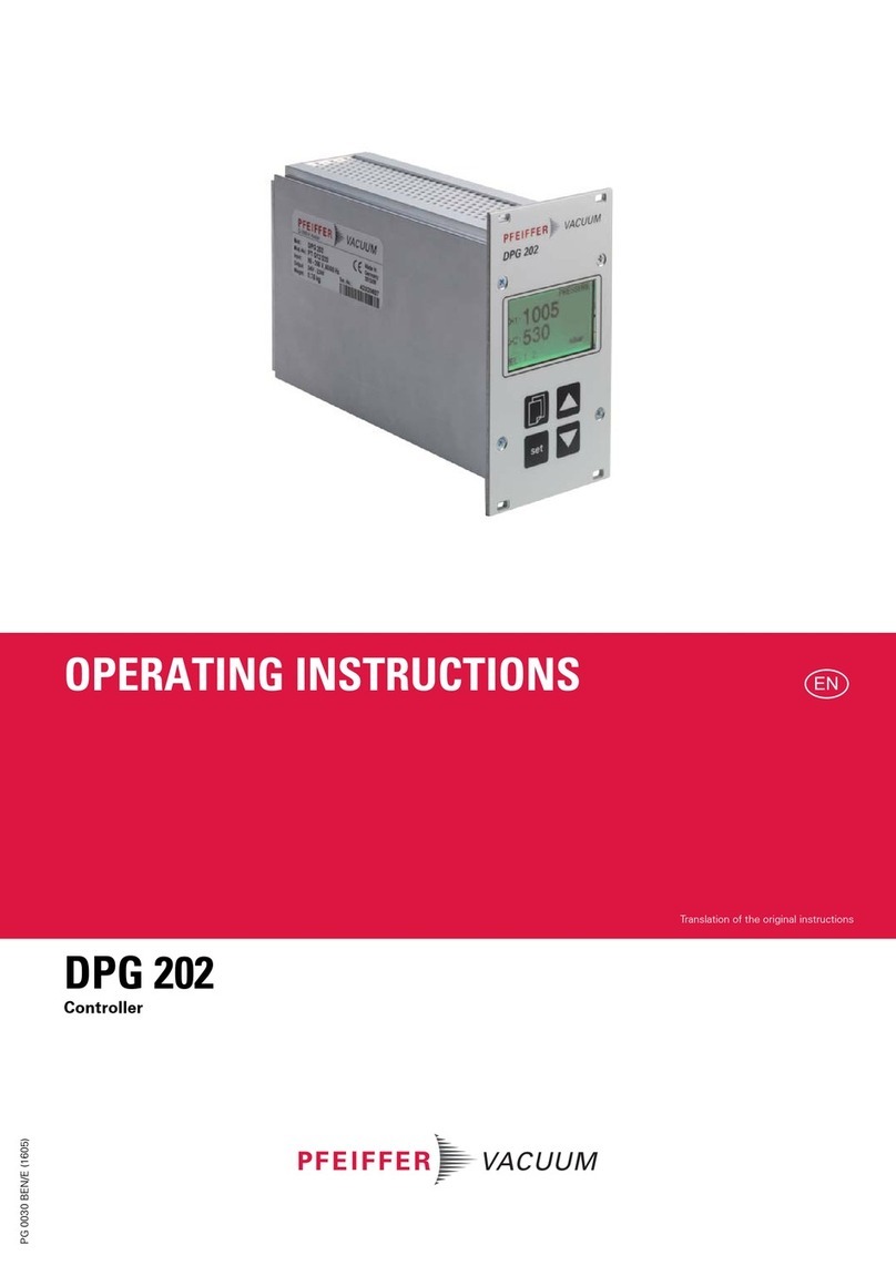
Pfeiffer Vacuum
Pfeiffer Vacuum DPG 202 User manual

