Madas FRG-RG/2MCSH User manual

FRG/2MBH
FRG-RG/2MCSH
MADE IN ITALY
II 2G - II 2D
0497
REGOLATORE DI PRESSIONE PER GAS
GAS PRESSURE REGULATOR
REGULATEUR DE PRESSION POUR GAZ
REGULADOR DE PRESIÓN PARA GAS
FRG-RG/2MCSH
FRG/2MBH (Z/F/R/M)
Chapter
5.4a
SeC tion
5
Madas Technical Manual - 5|5.4a - REV. 0 of th Sep 2019 - FRG-RG/2MCSH - FRG/2MBH (Z/F/R/M)
IT EN FR ES
Range pressione di esercizio
Operating pressure range
Plage de pression de fonctionnement
Rango de la presión de funcionamiento
Pe: 0,5÷5 bar
Pa: 0,9÷3 bar
Attacchi filettati / Threaded connections
Raccords filetés / Conexiones roscadas
DN 15 - DN 20 - DN 25
Attacchi flangiati/ Flanged connections
Raccords à brides / Conexiones embridadas
DN 25
Norma di riferimento / Reference standard
Norme de référence / Patrón de referencia EN 88-2
In conformità a *
In conformity with *
Conforme a *
Conforme *
Direttiva PED
2014/68/UE
PED Directive
2014/68/EU
Directive PED
2014/68/UE
Directiva PED
2014/68/UE

ES FR EN IT
2Madas Technical Manual - 5|5.4a - REV. 0 of th Sep 2019FRG-RG/2MCSH - FRG/2MBH (Z/F/R/M)
INDICE INDEX INDEX ÍNDICE
pag.
Italiano ........................................................................................................................................................3
English ........................................................................................................................................................12
Français ......................................................................................................................................................21
Español .......................................................................................................................................................30
Disegni - Drawings - Dessins - Diseños ............................................................................................................39
Caratteristiche molle di regolazione (tabella 1) ....................................................................................................44
Regulation spring data (table 1) .......................................................................................................................
Caracteristiques des ressorts de reglage (tableau 1) ...........................................................................................
Características muelles de regulación (tabla 1) ...................................................................................................
Codifica prodotto / Product encoding / Codification du produit / Codificación del producto.......................................45
Portate regolatori (tabella 2)................................................................................................................................ 50
Capacities of regulators (table 2) .....................................................................................................................
Débit des régulateurs (tableau 2).....................................................................................................................
Caudal de los reguladores (tabla 2)..................................................................................................................
Dimensioni (tabella 3a-3b) .............................................................................................................................50
Dimensions (table 3a-3b) ..............................................................................................................................
Dimensions (tableau 3a-3b)............................................................................................................................
Dimensiones (tabla 3a-3b) ............................................................................................................................

IT EN FR ES
3
Madas Technical Manual - 5|5.4a - REV. 0 of th Sep 2019 FRG-RG/2MCSH - FRG/2MBH (Z/F/R/M)
1.0 GENERALITÀ
Il presente manuale illustra come installare, far funzionare e utilizzare il dispositivo in modo sicuro.
Le istruzioni per l’uso devono essere SEMPRE disponibili nell’impianto dove è installato il dispositivo.
ATTENZIONE: le operazioni di installazione/manutenzione devono essere eseguite da personale
qualificato (come indicato in 1.3) utilizzando adeguati dispositivi di protezione individuale (DPI).
Per eventuali informazioni relative alle operazioni di installazione/manutenzione o in caso di problemi non risolvibili con
l’utilizzo delle istruzioni è possibile contattare il produttore utilizzando indirizzo e recapiti telefonici riportati in ultima pagina.
1.1 DESCRIZIONE
Dispositivo che eroga “a valle” un valore di pressione (Pa) predefinito e costante (entro i limiti di funzionamento previsti) al
variare della pressione in ingresso (Pe) e/o della portata (Q). L’otturatore compensato garantisce precisione nella regolazione
della pressione in uscita (Pa) anche nel caso di elevate e improvvise variazioni della pressione in entrata.
Questi regolatori sono impiegati in impianti che utilizzano Gas naturale, GPL o altri gas non corrosivi (gas secchi).
Norme di riferimento: EN 88-2 – EN 13611.
Possono essere dotati dei seguenti dispositivi di sicurezza e accessori a seconda delle esigenze dell’impianto:
• dispositivo di blocco per sovrappressione a valle (OPSO -
modelli FRG/2MBH...
): interrompe
l’erogazione quando la pressione in uscita del regolatore supera il valore di taratura del dispositivo. Su questi apparecchi il
dispositivo OPSO è sempre presente.
• dispositivo di blocco di minima pressione a valle (UPSO - modelli FRG/2MBH...): interrompe
l’erogazione quando la pressione in uscita del regolatore scende al di sotto del valore di taratura del dispositivo. Interviene
anche in caso di mancanza di alimentazione a monte. Possono essere forniti anche senza dispositivo UPSO.
• valvola di sfioro: scarica all’esterno piccole portate di gas nel caso si verifichino sovrappressioni a valle del regolatore.
Tale scarico è convogliabile all’esterno nel caso di installazioni in ambienti con scarsa ventilazione. Possono essere forniti
anche senza valvola di sfioro.
• presa di pressione in uscita.
1.2 LEGENDA SIMBOLI
ATTENZIONE: Viene
richiamata l’attenzione su
dettagli tecnici rivolti al
personale qualificato.
PERICOLO:
In caso di inosservanza
oltre a danni a beni materiali, possono
essere procurati danni alle persone e/o
animali domestici.
PERICOLO: In caso di
inosservanza possono
essere procurati danni a
beni materiali.
1.3 PERSONALE QUALIFICATO
Trattasi di persone che:
•Hanno dimestichezza con l’installazione, il montaggio, la messa in servizio e la manutenzione del prodotto;
•Sono a conoscenza delle normative in vigore nella regione o paese in materia di installazione e sicurezza;
•Hanno istruzione sul pronto soccorso.
1.4 USO DI PARTI DI RICAMBIO NON ORIGINALI
•In caso di manutenzione o sostituzione di componenti di ricambio (es. molla, organo filtrante, ecc.) devono essere utilizzati
SOLAMENTE quelli indicati dal fabbricante. L’utilizzo di componenti differenti, oltre a far decadere la garanzia del
prodotto, potrebbe compromettere il corretto funzionamento dello stesso.
•Il fabbricante non è responsabile di malfunzionamenti derivanti da manomissioni non autorizzate o utilizzo di ricambi non originali.
1.5 UTILIZZO NON APPROPRIATO
•Il prodotto deve essere utilizzato unicamente allo scopo per il quale è stato costruito.
•Non è consentito l’utilizzo con fluidi differenti da quelli indicati.
• Non devono essere superati in nessun caso i dati tecnici indicati in targhetta. E’ cura dell’utilizzatore finale o dell’installatore, adottare
corretti sistemi a protezione dell’apparecchio che impediscano il superamento della pressione massima indicata in targhetta.
•Il fabbricante non è responsabile per danni causati da un utilizzo improprio dell’apparecchio.

ES FR EN IT
4Madas Technical Manual - 5|5.4a - REV. 0 of th Sep 2019FRG-RG/2MCSH - FRG/2MBH (Z/F/R/M)
2.0 DATI TECNICI
• Impiego : gas non aggressivi delle tre famiglie (gas secchi)
• Temperatura ambiente : -20 ÷ +60 °C
• Pressione minima di funzionamento : 0,5 bar
• Pressione max di esercizio : 5 bar
• Pressione ammissibile PS : 5 bar
• Tempo di chiusura blocchi di sicurezza : < 1 s
• Classe di accuratezza : AC=10 - (Pa ± 10%)
• Gruppo accuratezza blocco sovrapressione
: AG=10 (solo modelli 2MBH...)
• Classe pressione di chiusura : SG=10
• Valvola di sfioro : testata secondo indicazioni riportate su EN 334
• Connessione dello sfiato : G 1/4
• Resistenza meccanica : Gruppo 2 (secondo EN 13611)
• Attacchi filettati Rp : (DN 15 - DN 20 - DN 25) secondo EN 10226
• Attacchi filettati NPT : su richiesta
• Attacchi flangiati accoppiabili con flange PN 16
: su richiesta DN 25 con flange girevoli
• Organo filtrante standard : filtraggio 50µm (su versioni FRG...)
• In conformità a : Direttiva PED 2014/68/UE - Direttiva ATEX 2014/34/UE
2.1 INDIVIDUAZIONE MODELLI (per configurazioni vedere pag. 45 - 49)
FRG/2MCSH: Regolatore di pressione con filtro - senza blocchi di sicurezza
RG/2MCSH: Regolatore di pressione senza filtro - senza blocchi di sicurezza
FRG/2MBH (Z-F-R-M): Regolatore di pressione con filtro - con blocchi di sicurezza
Z: Connessioni in linea
F: Connessioni a 90° IN G 1/2
R: Connessioni a 90° OUT G 3/4
M: Connessioni a “U” IN G 1/2 - OUT G 3/4
3.0 MESSA IN FUNZIONE DEL DISPOSITIVO
3.1 OPERAZIONI PRELIMINARI ALL’INSTALLAZIONE
•E’ necessario chiudere il gas a monte dell’apparecchio prima dell’installazione;
•Verificare che la pressione di linea NON SIA SUPERIORE alla pressione massima dichiarata sull’etichetta del prodotto;
•Eventuali tappi di protezione (se presenti) vanno rimossi prima dell’installazione;
•Tubazioni e interni dell’apparecchio devono essere liberi da corpi estranei;
•IMPORTANTE:
•per evitare possibili pompaggi e/o disturbi nel flusso del gas deve essere previsto (a valle del regolatore) un tratto
rettilineo di tubazione pari ad almeno 5 DN;
•prevedere l’installazione di dispositivi di chiusura manuale del gas (es. valvole a sfera) a monte e valle del regolatore
per proteggerlo da eventuali prove di tenuta delle tubature;
•tenere in considerazione che se il regolatore è dotato di valvola di sfioro, quest’ultima è idonea allo scarico di piccole
quantità di gas e NON può sostituire la valvola di sfioro installata a parte come dispositivo specifico;

IT EN FR ES
5
Madas Technical Manual - 5|5.4a - REV. 0 of th Sep 2019 FRG-RG/2MCSH - FRG/2MBH (Z/F/R/M)
Se l’apparecchio è filettato:
verificare che la lunghezza del filetto della tubazione non sia eccessiva per non danneggiare il corpo dell’apparecchio
in fase di avvitamento;
Se l’apparecchio è flangiato:
•verificare che le controflange di ingresso e uscita siano perfettamente coassiali e parallele per evitare di sottoporre il
corpo a inutili sforzi meccanici, calcolare inoltre lo spazio per l’inserimento della guarnizione di tenuta;
•Per le fasi di serraggio, è necessario munirsi di una o più chiavi dinamometriche tarate od altri utensili di bloccaggio controllati;
•In caso di installazione all’esterno, è consigliato prevedere una tettoia di protezione per evitare che l’acqua piovana possa
ossidare o danneggiare parti dell’apparecchio.
•In base alla geometria dell’impianto valutare il rischio di formazione di miscela esplosiva all’interno della tubazione;
•Se il regolatore è installato in prossimità di altre apparecchiature o come parte di un insieme, è necessario valutare
preliminarmente la compatibilità fra il regolatore e tali apparecchiature;
•Prevedere una protezione da urti o contatti accidentali nel caso l’apparecchio sia accessibile a personale non qualificato.
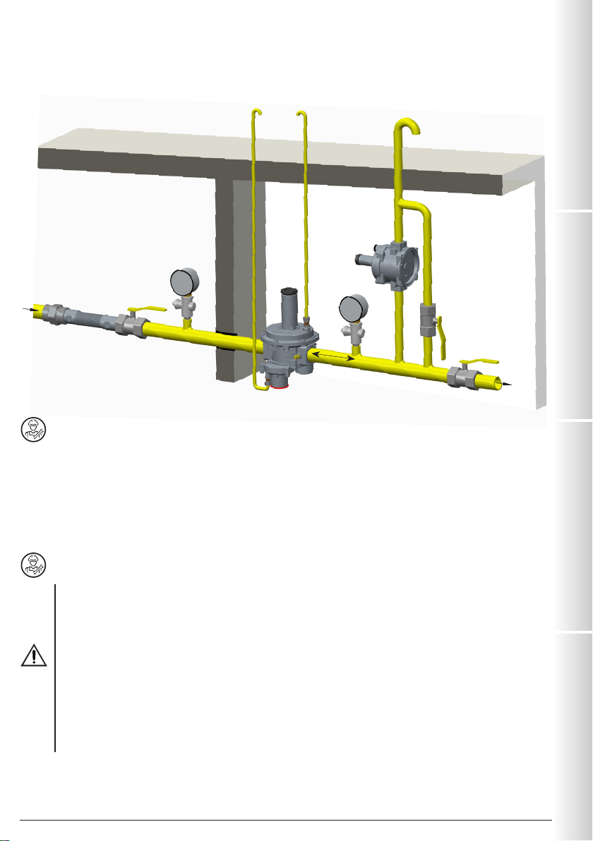
3.2 INSTALLAZIONE (vedere esempio in 3.4)
Apparecchi filettati:
•Assemblare il dispositivo avvitandolo, assieme alle opportune tenute, sull’impianto con tubi e/o raccordi le cui filettature
siano coerenti con la connessione da assemblare;
•Non usare il collo del coperchio superiore (3) come leva per l’avvitamento ma servirsi dell’apposito utensile;
•La freccia, indicata sul corpo (6) dell’apparecchio, deve essere rivolta verso l’utenza;
Apparecchi flangiati:
•Assemblare il dispositivo flangiandolo, assieme alle opportune tenute, all’impianto con tubi le cui flange siano coerenti con
la connessione da assemblare. Le guarnizioni devono essere prive di difetti e devono essere centrate tra le flange;
•Se a guarnizioni inserite lo spazio rimanente è eccessivo non cercare di colmare il gap stringendo eccessivamente i bulloni
dell’apparecchio;
•La freccia, indicata sul corpo (6) dell’apparecchio, deve essere rivolta verso l’utenza;
•Inserireall’interno dei bulloni le apposite rondelleperevitaredanneggiamenti
alle flange in fase di serraggio;
•Durante la fase di serraggio prestare attenzione a non “pizzicare” o
danneggiare la guarnizione;
•Serrare i dadi o bulloni gradualmente, secondo uno schema “a croce”
(vedere esempio a lato);
•Serrarli, prima al 30%, poi al 60%, fino al 100% della coppia massima
(vedere tabella a lato secondo EN 13611);
• Serrare nuovamente ogni dado o bullone in senso orario almeno una volta, fino al raggiungimento dell’uniformità della coppia massima;
Procedure in comune (apparecchi filettati e flangiati):
•Il regolatore è normalmente posizionato prima dell’utenza e p
uò essere installato in qualsiasi posizione anche se è preferibile
l’installazione come in 3.4 (esempio di installazione). All’esterno del regolatore, a valle dello stesso, è sistemata una presa di
pressione (24) per il controllo della pressione di regolazione (Pa);
• Canalizzare all’esterno (come indicato in 3.4) lo scarico della valvola di sfioro (se presente) rimuovendo il tappo antipolvere (26);
•Si consiglia sempre l’installazione di un giunto di compensazione;
•Durante l’installazione evitare che detriti o residui metallici penetrino all’interno dell’apparecchio;
•Garantire un montaggio privo di tensioni meccaniche, è consigliato l’uso di giunti compensatori anche per sopperire alle
dilatazioni termiche della tubazione;
•In caso sia prevista l’installazione dell’apparecchio in una rampa, è cura dell’installatore prevedere adeguati supporti o
appoggi correttamente dimensionati, per sostenere e fissare l’insieme. Non lasciare, mai e per nessun motivo, gravare il
peso della rampa solo sulle connessioni (filettate o flangiate) dei singoli dispositivi;
•In ogni caso dopo l’installazione verificare la tenuta dell’impianto. Per effettuare la tenuta sul tratto di tubazione a valle:
•alimentare il regolatore con la pressione in ingresso;
•chiudere lentamente la valvola a sfera a valle del regolatore:
•assicurandosi che la valvola di sfioro e eventuali blocchi di sicurazza non internvengano, verificare che la pressione
(indicata sul manometro) rimanga stabile (non scenda).
Diametro DN 25
Coppia max (N.m) 30

ES FR EN IT
6Madas Technical Manual - 5|5.4a - REV. 0 of th Sep 2019FRG-RG/2MCSH - FRG/2MBH (Z/F/R/M)
3.3 INSTALLAZIONE IN LUOGHI A RISCHIO DI ESPLOSIONE (DIRETTIVA 2014/34/UE)
Il regolatore è conforme alla Direttiva 2014/34/UE (ex 94/9/CE) come apparecchio del gruppo II, categoria 2G e come apparecchio
del gruppo II, categoria 2D; come tale è idoneo per essere installato nelle zone 1 e 21 (oltre che nelle zone 2 e 22) come
classificate nell’allegato I alla Direttiva 99/92/CE. Il regolatore non è idoneo per l’utilizzo nelle zone 0 e 20 come definite nella già
citata Direttiva 99/92/CE. Per determinare la qualifica e l’estensione delle zone pericolose si veda la norma CEI EN 60079-10-1.
L’ apparecchio, se installato e sottoposto a manutenzione nel pieno rispetto di tutte le condizioni e istruzioni tecniche riportate
nel presente documento, non costituisce fonte di pericoli specifici: in particolare, in condizioni di normale funzionamento, è
prevista, da parte del regolatore, l’emissione in atmosfera di sostanza infiammabile solo occasionalmente, e precisamente:
Il regolatore può essere pericoloso rispetto alla presenza nelle sue vicinanze di altre apparecchiature in caso di intervento
della valvola di sfioro integrata o in caso di rottura della membrana di funzionamento (25) o della membrana di blocco (14).
Nei casi di rottura membrane il regolatore costituisce una sorgente di emissione di atmosfera esplosiva di grado continuo e,
come tale, può originare zone pericolose 0 come definite nella Direttiva 99/92/CE.
In condizioni di installazione particolarmente critica (luoghi non presidiati, carenza di manutenzione, scarsa disponibilità di
ventilazione) e, soprattutto in presenza nelle vicinanze del regolatore di potenziali fonti di innesco e/o apparecchiature pericolose
nel funzionamento ordinario in quanto suscettibili di originare archi elettrici o scintille, è necessario valutare preliminarmente
la compatibilità fra il regolatore e tali apparecchiature.
In ogni caso è necessario prendere ogni precauzione utile ad evitare che il regolatore sia origine di zone 0: ad esempio verifica
periodica annuale di regolare funzionamento, possibilità di modificare il grado di emissione della sorgente o di intervenire sullo
scarico della sostanza esplosiva canalizzandola all’esterno. A tal fine è sufficiente rimuovere i tappi antipolvere (26) e (29)
raccordando apposito tubo (rispettivamente G 1/4 e G 1/8) convogliato all’esterno (vedere esempio di installazione in 3.4).
3.4 ESEMPI GENERICI DI INSTALLAZIONE
ESEMPIO 1 (modelli 2MCSH...)
1. Giunto di compensazione/antivibrante
2. Valvola a sfera a monte
3. Filtroregolatore di pressione FRG/2MCSH
4. Valvola a sfera a valle del regolatore
5. Rubinetto di sfiato
6. Valvola di sfioro MVS/1
7. Manometro bassa pressione e relativo pulsante
8. Manometro alta pressione e relativo pulsante
1
2
3
4
5
6
7
8
rete
utenza
scarico in
aria libera
scarico in
aria libera
5 DN
teoia esterna

IT EN FR ES
7
Madas Technical Manual - 5|5.4a - REV. 0 of th Sep 2019 FRG-RG/2MCSH - FRG/2MBH (Z/F/R/M)
ESEMPIO 2 (modelli 2MBH...)
1. Giunto di compensazione/antivibrante
2. Valvola a sfera a monte
3. Filtroregolatore di pressione FRG/2MBH...
4. Valvola a sfera a valle del regolatore
5. Rubinetto di sfiato
6. Valvola di sfioro MVS/1
7. Manometro bassa pressione e relativo pulsante
8. Manometro alta pressione e relativo pulsante
4.0 RIARMO MANUALE
•Assicurarsi che tutte le valvole e i rubinetti a valle siano chiusi;
•Svitare il tappo (10);
•Premere leggermente il perno di riarmo (18), attendere qualche istante che si verifichi l’equilibrio di pressione e
successivamente premere fino a fine corsa il perno di riarmo (18);
•Tenendo premuto il perno di riarmo (18), aprire lentamente il rubinetto a valle del regolatore;
•Rilasciare il perno di riarmo (18);
•Successivamente riavvitare il tappo (10) nella posizione iniziale.
5.0 PRIMA MESSA IN SERVIZIO
Prima della messa in servizio verificare che:
•tutte le indicazioni presenti in targhetta, inclusa la direzione del flusso, siano rispettate;
•i fori dei tappi antipolvere (26) e (29) non siano ostruiti (regolatore e blocco);
•IMPORTANTE: Servirsi di appositi dispositivi manuali di chiusura del gas per evitare il danneggiamento del
regolatore;
•La manovra di pressurizzazione dell’apparecchiatura, dovrà essere fatta molto lentamente per evitare possibili danni.
Per effettuare la tenuta sul tratto di tubazione a valle:
•alimentare il regolatore con la pressione in ingresso;
•chiudere lentamente la valvola a sfera a valle del regolatore:
•assicurandosi che la valvola di sfioro e eventuali blocchi di sicurazza non internvengano, verificare che la
pressione (indicata sul manometro) rimanga stabile (non scenda).
NOTA: non deve essere per nessun motivo posizionato un tappo cieco al posto dei tappi antipolvere (26) e (29)
in quanto il regolatore e/o i blocchi di sicurezza potrebbero non funzionare;
•Chiudere la valvola a sfera a valle del regolatore e aprire parzialmente il rubinetto di sfiato a valle;
•Aprire lentamente gli apparecchi di intercettazione a monte;
•Chiudere il rubinetto di sfiato;
•Procedere con il riarmo manuale del regolatore (vedere 4.0);
1
2
34
5
6
7
8
rete
utenza
scarico in
aria libera
scarico in
aria libera
5 DN
teoia esterna

ES FR EN IT
8Madas Technical Manual - 5|5.4a - REV. 0 of th Sep 2019FRG-RG/2MCSH - FRG/2MBH (Z/F/R/M)
•Chiudere il rubinetto a valle così da portare in chiusura il regolatore (il valore della Pa aumenta del valore di SG per portare
l’otturatore in posizione di totale chiusura);
•Verificare la tenuta delle guarnizioni dell’impianto e verificare la tenuta interna/esterna del regolatore, dello sfioro e del tubo
sensore esterno se presente;
•Aprire lentamente il rubinetto a valle e la valvola di intercettazione;
•Verificare il funzionamento del regolatore;
6.0 TARATURA
Prima di eseguire le operazioni assicurarsi che la molla/e in dotazione siano adeguate ai campi desiderati di Pa - OPSO - UPSO
e differenziale sfioro.
6.1 - Regolazione del blocco di massima pressione (OPSO - modelli FRG/2MBH...)
•Svitare il tappo (10);
•Con la chiave in dotazione (28) avvitare al massimo la ghiera di regolazione del blocco di massima (16);
•Avviare l’impianto, riarmare il dispositivo di blocco come indicato in 4.0 e assicurarsi che non vi sia consumo di gas (chiudere
le utenze a valle del regolatore);
•Servendosi di una pressione di gas ausiliaria, aumentare lentamente la pressione di valle fino al valore desiderato e
contemporaneamente, svitare con la chiave in dotazione (28) la ghiera (16) fino all’intervento del dispositivo (in questo
modo si evita di dover settare nuovamente la Pa);
•Riarmare il sistema seguendo la giusta procedura e verificare che il valore di intervento sia quello desiderato ripetendo
l’operazione di sgancio 2-3 volte;
•Se necessario aggiustare il valore di intervento agendo sulla ghiera (16) con l’apposita chiave (28).
6.2 - Regolazione del blocco di minima pressione (UPSO - modelli FRG/2MBH...)
•Svitare il tappo (10);
•Con la chiave in dotazione (28) svitare al minimo la ghiera di regolazione del blocco di minima (17);
•Avviare l’impianto e riarmare il dispositivo di blocco come indicato al punto 4.0;
•Diminuire la pressione di valle fino al valore di intervento desiderato;
•Utilizzando la chiave in dotazione (28), avvitare la ghiera di regolazione (17) fino all’intervento del blocco di minima pressione.
•Riarmare il sistema seguendo la giusta procedura e verificare che il valore di intervento sia quello desiderato ripetendo
l’operazione di sgancio 2-3 volte;
•Se necessario aggiustare il valore di intervento agendo sulla ghiera (17) con apposita chiave (28);
6.3 - Regolazione dello sfioro (differenziale DfRv)
NOTA: Lo sfioro (se presente) in questi regolatori è differenziale, pertanto il valore del range (DfRv) indicato va sommato al
valore del range della pressione in uscita (Pa).
Esempio: Pa=0,9÷1,5 bar - DfRv=0,2÷1 bar.
Significa che lo sfioro è tarabile da: (Pa min + DfRv min) = 0,9+0,2=1,1 bar a: (Pa min + DfRv max) = 0,9+1=1,9 bar
(Pa max + DfRv min) = 1,5+0,2=1,7 bar a: (Pa max + DfRv max) = 1,5+1=2,5 bar
Quindi il campo effettivo dello sfioro è: con Pa min è 1,1÷1,9 bar
con Pa max è 1,7÷2,5 bar
•Avviare l’impianto e armare il blocco come indicato al punto 4.0;
•Chiudere lentamente il rubinetto a valle del regolatore;
•Svitare e rimuovere il tappo (27);
•Con chiave a tubo da 8mm (vedere fig. 1 e 2b) avvitare a fine corsa il dado (21);
•Premendo con la chiave a tubo da 8 mm sul dado di regolazione (21), aumentare la pressione Pa, leggendola sul manometro,
fino al valore di taratura voluto;
•Senza premere ulteriormente, svitare lentamente il dado di regolazione (21) finchè la pressione Pa, visualizzata sul manometro
inizia a diminuire;
•Lo sfioro è in questo caso tarato al valore desiderato;
•Rimuovere la chiave a tubo e chiudere il tappo (27).

IT EN FR ES
9
Madas Technical Manual - 5|5.4a - REV. 0 of th Sep 2019 FRG-RG/2MCSH - FRG/2MBH (Z/F/R/M)
6.4 - Regolazione della pressione in uscita (Pa)
La pressione in uscita Pa (salvo richieste specifiche) è impostata di fabbrica con il regolatore installato come in 3.4 e con
la vite di regolazione (1) settata circa al valore minimo di taratura. I blocchi di sicurezza/sfioro sono settati di conseguenza;
Se il regolatore è installato in posizioni diverse, verificare e reimpostare la pressione in uscita Pa e di conseguenza dei
dispositivi incorporati nel regolatore;
Per la regolazione della pressione di uscita:
•Svitare il tappo (27);
•Svitare la vite di regolazione (1) posizionandola al minimo di taratura consentito (estremità filettata del coperchio superiore (3))
;
•Avviare l’impianto o assicurarsi che ci sia un minimo di portata a valle del regolatore;
•Per aumentare la taratura della pressione a valle del regolatore avvitare la vite di regolazione (1) fino al valore desiderato.
Effettuare la lettura con manometro tarato, installato a valle del regolatore ad almeno 5 DN (vedere esempio in 3.4);
•Riavvitare il tappo (27) ed eventualmente sigillarlo in quella posizione utilizzando (se presenti) gli appositi fori sigillo;
•Utilizzare le prese di pressione (24) sull’apparecchio solo per misurazioni a portata zero o a portata molto ridotta.
7.0 - VERIFICHE PERIODICHE CONSIGLIATE
•Verificare con apposito strumento tarato che il serraggio dei bulloni sia conforme a quanto indicato in 3.2;
•Verificare la tenuta delle connessioni flangiate/filettate sull’impianto;
•Verificare la tenuta e il funzionamento del regolatore/blocco/sfioro;
E’ cura dell’utilizzatore finale o dell’installatore definire la frequenza delle suddette verifiche in base alla gravità delle condizioni
di servizio.
7.1 - VERIFICA FUNZIONAMENTO VALVOLA DI BLOCCO DI MASSIMA PRESSIONE
(OPSO - modelli FRG/2MBH...)
•Riarmare il dispositivo di blocco e chiudere il rubinetto a valle del regolatore;
•Servendosi di una pressione di gas ausiliaria, aumentare lentamente la pressione di valle fino all’intervento del dispositivo
(in questo modo si evita di dover settare nuovamente la Pa).
7.2 - VERIFICA FUNZIONAMENTO VALVOLA DI BLOCCO DI MINIMA PRESSIONE
(UPSO - modelli FRG/2MBH...)
•Riarmare il dispositivo di blocco e chiudere la valvola a sfera a monte del regolatore;
•aprire parzialmente e lentamente il rubinetto di sfiato a valle del dispositivo. La pressione in uscita, abbassandosi, farà
intervenire il blocco di minima al suo valore di taratura;
•Ripetere le operazioni di intervento 2-3 volte così da accertare il corretto funzionamento del sistema. Tra un intervento e
l’altro riportare la pressione di valle al valore di taratura.
7.3 - VERIFICA TENUTA DISPOSITIVI DI SICUREZZA (OPSO E UPSO - versioni FRG/2MBH...)
•Svuotare completamente il tratto di tubazione di valle, (aspettare alcuni secondi in modo da permettere il totale svuotamento).
Richiudendo il rubinetto di sfiato, la pressione a valle deve rimanere a zero.
7.4 - VERIFICA DEL FUNZIONAMENTO DELLO SFIORO
•Avviare l’impianto e armare il blocco come indicato al punto 4.0;
•Chiudere lentamente il rubinetto a valle del regolatore;
•Svitare e rimuovere il tappo (27);
•Premendo con chiave a tubo da 8 mm sul dado di regolazione (21), aumentare la pressione Pa al di sopra del valore
preimpostato ma evitando di far intervenire il blocco OPSO. Servirsi di un manometro tarato per la lettura;
•Togliere la chiave a tubo. La sovrappressione creata verrà scaricata all’esterno, la Pa inizierà a diminuire fino al valore di
taratura dello sfioro. Il funzionamento dello sfioro è verificato;
•Chiudere il tappo (27);
•Aprire il rubinetto di sfiato per scaricare la sovrappressione creata;
•Chiudere il rubinetto di sfiato (il regolatore si porta alla pressione di chiusura) e aprire la valvola a sfera a valle del regolatore.

ES FR EN IT
10 Madas Technical Manual - 5|5.4a - REV. 0 of th Sep 2019FRG-RG/2MCSH - FRG/2MBH (Z/F/R/M)
8.0 MANUTENZIONE
•Non sono previste operazioni di manutenzione interne dell’apparecchio. Nel caso sia necessario effettuare delle
operazioni interne all’apparecchio (cambio molla, sostituzione filtro, ecc.) si consiglia di contattare l’Ufficio Tecnico.
In ogni caso prima di effettuare qualsiasi operazione di smontaggio sull’apparecchio, assicurarsi che all’interno
dello stesso non ci sia gas in pressione.
9.0 TRASPORTO, STOCCAGGIO E SMALTIMENTO
• Durante il trasporto il materiale deve essere trattato con cura, evitando che il dispositivo possa subire urti, colpi o vibrazioni;
• Se il prodotto presenta trattamenti superficiali (es. verniciatura, cataforesi, ecc) non devono essere danneggiati durante
il trasporto;
• La temperatura di trasporto e di stoccaggio, coincide con quella indicata nei dati di targa;
• Se il dispositivo non viene installato subito dopo la consegna deve essere correttamente immagazzinato in un luogo secco e pulito;
• In ambienti umidi è necessario usare siccativi oppure il riscaldamento per evitare la condensa;
• Il prodotto, a fine vita, dovrà essere smaltito in conformità alla legislazione vigente nel paese in cui si esegue tale operazione.
10.0 GARANZIA
Valgono le condizioni di garanzia stabilite col fabbricante al momento della fornitura.
Per danni causati da:
• Uso improprio del dispositivo;
• Inosservanza delle prescrizioni indicate nel presente documento;
• Inosservanza delle norme riguardanti l’installazione;
• Manomissione, modifica e utilizzo di parti di ricambio non originali;
non possono essere rivendicati diritti di garanzia o risarcimento danni.
Sono esclusi inoltre dalla garanzia i lavori di manutenzione, il montaggio di apparecchi di altri produttori, la modifica del
dispositivo e l’usura naturale.

IT EN FR ES
11
Madas Technical Manual - 5|5.4a - REV. 0 of th Sep 2019 FRG-RG/2MCSH - FRG/2MBH (Z/F/R/M)
11.0 DATI DI TARGA
In targa (vedere esempio sopra) sono riportati i seguenti dati:
• Nome/logo e indirizzo del fabbricante (eventuale nome/logo distributore)
• Mod.: = nome/modello dell’apparecchio seguito dal diametro di connessione
• PS =
Pressione ammissibile
• Pe =
Pressione massima o range di pressione di ingresso alla quale è garantito il funzionamento del prodotto
• (-20...+60) °C = Range di temperatura alla quale è garantito il funzionamento del prodotto
• Pa = Range pressione di uscita
• Wdso (se presente) = Range taratura OPSO ottenibile con la molla in dotazione (senza sostituire alcun componente)
• AC = Classe di accuratezza Pa
• SG = Classe pressione di chiusura
• AG =
Gruppo accuratezza blocco sovrapressione
• EN 88-2 = Norma di riferimento del prodotto
• Wdsu (se presente) = Range taratura UPSO ottenibile con la molla in dotazione (senza sostituire alcun componente)
• DfRv (se presente) = Range differenziale sfioro rispetto a Pa
• year = Anno di fabbricazione
• Lot = Numero matricola del prodotto (vedere spiegazione di seguito)
• U1823 = Lotto in uscita anno 2018 settimana n° 23
• 14216 = numero progressivo commessa riferito all’anno indicato
• 00001 = numero progressivo riferito alla q.tà del lotto
• = Conformità Dir. ATEX seguita dal modo di protezione
• = Conformità Dir. PED seguita dal n° dell’Organismo Notificato
Mod.: FRG/2MCSH DN 25 PS=Pe:0,5-5 bar (-20...+60)°C
Pa: 20-30 mbar DfRv:10-60 mbar AC10 SG10 EN 88-2
year: 2018 Lot:U1823 14216/00001
Via Moratello, 5/7 - 37045
Legnago (VR) - Italy
www.madas.it
0497
II2G
II2D
Mod.: FRG/2MBHZ DN 25 PS=Pe:0,5-5 bar (-20...+60)°C
Pa: 20-30 mbar Wdso:40-90 mbar AC10 SG10 AG10 EN 88-2
Wdsu:10-30 mbar DfRv:10-60 mbar
year: 2018 Lot:U1823 14216/00001
Via Moratello, 5/7 - 37045
Legnago (VR) - Italy
www.madas.it
0497
II2G
II2D
FRG-RG/2MCSH
FRG/2MBH

ES FR EN IT
12 Madas Technical Manual - 5|5.4a - REV. 0 of th Sep 2019FRG-RG/2MCSH - FRG/2MBH (Z/F/R/M)
1.0 GENERAL INFORMATION
This manual shows you how to safely install, operate and use the device.
The instructions for use ALWAYS need to be available in the facility where the device is installed.
ATTENTION: installation/maintenance needs to be carried out by qualified staff (as explained in
section 1.3) by using suitable personal protective equipment (PPE).
For any information pertaining to installation/maintenance or in case of problems that cannot be solved with the instructions,
contact the manufacturer at the address and phone numbers provided on the last page.
1.1 DESCRIPTION
Device which supplies a preset and constant “downstream” pressure value (Pa) (within the intended operating limits) according
to variations in the inlet pressure (Pe) and/or the flow rate (Q). The compensated obturator ensures precision when adjusting
the outlet pressure (Pa) even with high and sudden variations in the inlet pressure.
These regulators are used in plants where natural gas, LPG or other non-corrosive gases (dry gases) are used.
Reference standards: EN 88-2 – EN 13611.
They can be equipped with the following safety devices and accessories according to the system requirements:
• downstream overpressure shut off device (OPSO -
FRG/2MBH... models
): stops supply when the
regulator outlet pressure exceeds the setting value of the device. The OPSO device is always present on these devices.
• downstream minimum pressure shut off device (UPSO - FRG/2MBH... models): stops supply when the
regulator outlet pressure drops below the setting value of the device. It also intervenes in the event of an upstream power
failure. They can also be supplied without the UPSO device.
• relief valve: discharges small gas flows outwards if overpressure occurs downstream of the regulator. This discharge
can be conveyed outwards if the installation is in a poorly ventilated environment. They can also be supplied without the
relief valve.
• outlet pressure connection.
1.2 KEY TO SYMBOLS
ATTENTION: Attention
is drawn to the technical
details intended for
qualified staff.
DANGER: In the event of
inobservance, this may cause
damage to tangible goods, to people
and/or pets.
DANGER: In the event
of inobservance, this may
cause damage to tangible
goods.
1.3 QUALIFIED STAFF
These are people who:
•Are familiar with product installation, assembly, start-up and maintenance;
•Know the regulations in force in the region or country pertaining to installation and safety;
•Have first-aid training.
1.4 USING NONORIGINAL SPARE PARTS
•To perform maintenance or replace spare parts (e.g. spring, filter element, etc.) ONLY manufacturer-recommended parts
can be used. Using different parts not only voids the product warranty, it could compromise correct device operation.
•The manufacturer is not liable for malfunctions caused by unauthorised tampering or use of non-original spare parts.
1.5 IMPROPER USE
•The product must only be used for the purpose it was built for.
•It is not allowed to use fluids other than those expressly stated.
•The technical data provided on the rating plate must not, under any circumstances, be exceeded. The end user or installer is in
charge of implementing correct systems to protect the device, which prevent the maximum pressure indicated on the rating plate
from being exceeded.
•The manufacturer is not responsible for any damage caused by improper use of the device.

IT EN FR ES
13
Madas Technical Manual - 5|5.4a - REV. 0 of th Sep 2019 FRG-RG/2MCSH - FRG/2MBH (Z/F/R/M)
2.0 TECHNICAL DATA
• Use : non-aggressive gases of the three families (dry gases)
• Ambient temperature : -20 ÷ +60°C
• Minimum operating pressure : 0.5 bar
• Max operating pressure : 5 bar
• Allowable pressure PS : 5 bar
• Safety shut offs closing time : < 1 s
• Accuracy class : AC=10 - (Pa ± 10%)
• Overpressure shut off accuracy unit
: AG=10 (only 2MBH...models)
• Closing pressure class : SG=10
• Relief valve : tested according to the indications in EN 334
• Connecting the vent : G 1/4
• Mechanical strength : Group 2 (according to EN 13611)
• Rp Threaded connections : (DN 15 - DN 20 - DN 25) according to EN 10226
• NPT Threaded connections : on request
• Flanged connections that can couple with PN 16 flanges
: on request DN 25 with swivel flanges
• Standard filter element : filtering 50µm (on FRG... versions)
• In compliance with : PED Directive 2014/68/EU - ATEX Directive 2014/34/EU
2.1 MODEL IDENTIFICATION (for configurations see pages 45 - 49)
FRG/2MCSH: Pressure regulator with filter - without safety shut offs
RG/2MCSH: Pressure regulator without filter - without safety shut offs
FRG/2MBH (Z-F-R-M): Pressure regulator with filter - with safety shut offs
Z: Connections in line
F: Connections at 90° IN G 1/2
R: Connections at 90° OUT G 3/4
M: “U” Connections IN G 1/2 - OUT G 3/4
3.0 COMMISSIONING THE DEVICE
3.1 OPERATIONS PRIOR TO INSTALLATION
•It is necessary to close the gas upstream of the device prior to installation;
•Make sure that the line pressure DOES NOT EXCEED the maximum pressure declared on the product label;
•Protective caps (if any) must be removed prior to installation;
•The pipes and inside of the device must be clear of any foreign bodies;
•IMPORTANT:
•to avoid possible pumping and/or disturbances in the gas flow, a straight pipe section equal to at least 5 DN must be
installed (downstream of the regulator);
•install manual gas closing devices (e.g. ball valves) upstream and downstream of the regulator to protect it from any
pipe leak test;
•do consider that if the regulator is equipped with a relief valve, the latter is suitable for small quantities of gas to be
discharged and CANNOT replace the relief valve installed separately as a specific device;

ES FR EN IT
14 Madas Technical Manual - 5|5.4a - REV. 0 of th Sep 2019FRG-RG/2MCSH - FRG/2MBH (Z/F/R/M)
If the device is threaded:
make sure that the pipe thread is not too long, to prevent damaging the body of the device when screwing it on;
If the device is flanged:
•make sure the inlet and outlet counter-flanges are perfectly coaxial and parallel in order to prevent unnecessary
mechanical stress to the body. Also calculate the space to insert the seal gasket;
•With regard to tightening operations, equip yourself with one or two calibrated torque wrenches or other controlled locking
tools;
•With outdoor installation, it is advisable to install a protective roof to prevent rain from oxidising or damaging parts of the
device.
•According to the plant geometry, check the risk of an explosive mixture arising inside the piping;
•If the regulator is installed near other devices or as part of an assembly, compatibility between the regulator and
these devices must be evaluated beforehand;
•Provide protection against impact or accidental contact if the device is accessible to unqualified personnel.
3.2 INSTALLATION (see example in 3.4)
Threaded devices:
•Assemble the device by screwing it, with the due seals, onto the plant with pipes and/or fittings whose threads are consistent
with the connection being attached;
•Do not use the neck of the top cover (3) as a lever to help you screw it on, but only use the specific tool;
•The arrow, shown on the body (6) of the device, needs to be pointing towards the application;
Flanged devices:
•Assemble the device by flanging it, with the due seals, onto the plant with pipes whose flanges are consistent with the
connection being attached. The gaskets must be free from defects and must be centred between the flanges;
•If, after installing the gaskets, there is still too much space in between, do not try to reduce said gap by excessively tightening
the bolts of the device;
•The arrow, shown on the body (6) of the device, needs to be pointing towards the application;
•Insert the relative washers inside the bolts in order to prevent damage to the
flanges during the tightening stage;
•When tightening, be careful not to “pinch” or damage the gasket;
•Tighten the nuts or bolts gradually, in a “cross” pattern (see the example
at the side);
•Tighten them, first by 30%, then by 60% and finally 100% of the maximum
torque (see the table alongside according to EN 13611);
• Tighten each nut and bolt again clockwise at least once, until the maximum torque has been achieved uniformly;
Common procedures (threaded and flanged devices):
•The regulator is normally positioned before the application and
it can be installed in any position even if the installation shown
in 3.4 (installation example) is preferred. A pressure connection (24) can be found outside the regulator, downstream from it, to
control the regulation pressure (Pa);
• Drain the relief valve (if any) outwards (as shown in 3.4) by removing the dust cap (26);
•It is always recommended to install a compensation joint;
•During installation, avoid debris or metal residues from getting into the device;
•To guarantee mechanical tension-free assembly, we recommend using compensating joints, which also adjust to the pipe’s
thermal expansion;
•If the device is to be installed in a ramp, it is the installer’s responsibility to provide suitable supports or correctly sized
supports, to properly hold and secure the assembly. Never, for any reason whatsoever, leave the weight of the ramp only on
the connections (threaded or flanged) of the individual devices;
•In any case, following installation, check the tightness of the plant. To seal the downstream section of the pipe:
•feed the regulator with inlet pressure;
•slowly close the ball valve downstream of the regulator:
•ensuring that the relief valve and any safety shut-offs do not intervene, check that the pressure (indicated on the pressure
gauge) remains stable (does not drop).
Diameter DN 25
Max. torque (N.m) 30

IT EN FR ES
15
Madas Technical Manual - 5|5.4a - REV. 0 of th Sep 2019 FRG-RG/2MCSH - FRG/2MBH (Z/F/R/M)
3.3 INSTALLATION IN PLACES WHERE THERE IS THE RISK OF EXPLOSION (DIRECTIVE 2014/34/EU)
The regulator complies with Directive 2014/34/EU (formerly 94/9/EC) as group II equipment, category 2G and as group II
equipment, category 2D; consequently, it is suited for installation in zones 1 and 21 (in addition to zones 2 and 22) as classified
in Annex I of Directive 99/92/EC. The regulator is not suited for use in zones 0 and 20 as defined in the aforementioned Directive
99/92/EC. To determine the qualification and size of the danger zones, please refer to standard IEC EN 60079-10-1.
If installed and subject to maintenance in full compliance with all conditions and technical instructions provided in this manual,
the device does not pose a source of specific hazards: in particular, under conditions of normal operation, the regulator is
expected to emit a flammable substance into the atmosphere only occasionally, and specifically:
The regulator can be dangerous with respect to the presence of other devices nearby if the integrated relief valve is triggered
or if the working diaphragm (25) or the blocking diaphragm (14) fails. If the diaphragm fails, the regulator becomes a source
of explosive atmosphere emission of continuous degree and, as such, it can generate hazardous areas 0 as defined in Directive
99/92/EC.
In particularly critical installation conditions (unattended areas, poor maintenance or poor ventilation) and especially if there are
potential sources of ignition and/or hazardous equipment near the regulator in regular operation, as they may generate electric
arcs or sparks, a preliminary assessment of the compatibility between the regulator and such equipment must be carried out.
In any case, every useful precaution must be adopted so as to prevent the regulator from generating zones 0: for example,
annually verify regular operation, possibility of changing the degree of emission of the source or intervening on the explosive
substance discharge by directing it outwards. To do so, simply remove the dust caps (26) and (29) by connecting the specific
pipe (respectively, G 1/4 and G 1/8) conveyed to the outside (see example of installation in 3.4).
3.4 GENERAL EXAMPLES OF INSTALLATION
EXAMPLE 1 (2MCSH... models)
1. Expansion joint/anti-vibration mount
2. Upstream ball valve
3. FRG/2MCSH pressure regulator filter
4. Ball valve downstream of the regulator
5. Vent valve
6. Relief valve MVS/1
7. Low pressure gauge and relative button
8. High pressure gauge and relative button
1
2
3
4
5
6
7
8
piping
applicaon
discharge in
open air
discharge in
open air
5 DN
external roof

ES FR EN IT
16 Madas Technical Manual - 5|5.4a - REV. 0 of th Sep 2019FRG-RG/2MCSH - FRG/2MBH (Z/F/R/M)
EXAMPLE 2 (2MBH... models)
1. Expansion joint/anti-vibration mount
2. Upstream ball valve
3. FRG/2MBH... pressure regulator filter
4. Ball valve downstream of the regulator
5. Vent valve
6. Relief valve MVS/1
7. Low pressure gauge and relative button
8. High pressure gauge and relative button
4.0 MANUAL RESET
•Make sure that all valves and downstream taps are closed;
•Unscrew the cap (10);
•Lightly press the reset pin (18), wait a few moments for the pressure to balance and then fully press the reset pin (18);
•Hold down the reset pin (18), slowly open the valve downstream of the regulator;
•Release the reset pin (18);
•Then tighten the cap (10) back in the initial position.
5.0 FIRST STARTUP
Before commissioning, verify that:
•all of the instructions on the rating plate, including the direction of flow, are observed;
•the holes of the dust caps (26) and (29) are not clogged (regulator and shut off);
•IMPORTANT: Use special manual gas closing devices to avoid damaging the regulator;
•The pressurisation manoeuvre of the equipment must be carried out very slowly so as to avoid possible damage.
To seal the downstream section of the pipe:
•feed the regulator with inlet pressure;
•slowly close the ball valve downstream of the regulator:
•ensuring that the relief valve and any safety shut-offs do not intervene, check that the pressure (indicated on
the pressure gauge) remains stable (does not drop).
NOTE: under no circumstances should a blind cap be installed in place of dust caps (26) and (29) as the
regulator and/or the safety shut offs may not work;
•Close the ball valve downstream of the regulator and partially open the downstream relief valve;
•Slowly open the upstream shut-off devices;
•Close the vent valve;
•Proceed by manually resetting the regulator (see 4.0);
1
2
34
5
6
7
8
piping
applicaon
discharge in
open air
discharge in
open air
5 DN
external roof

IT EN FR ES
17
Madas Technical Manual - 5|5.4a - REV. 0 of th Sep 2019 FRG-RG/2MCSH - FRG/2MBH (Z/F/R/M)
•Close the downstream valve so as to close the regulator (the Pa value increases the SG value to fully close the obturator);
•Check the tightness of the system seals and check the internal/external tightness of the regulator, of the relief valve and of
the external sensor tube, if applicable;
•Slowly open the downstream valve and the shut-off valve;
•Check the operation of the regulator.
6.0 SETTING
Before carrying out the operations, make sure that the supplied spring/s is/are suitable for the desired Pa - OPSO - UPSO and
differential relief valve fields.
6.1 - Adjusting the maximum pressure shut off (OPSO - FRG/2MBH... models)
•Unscrew the cap (10);
•Use the supplied key (28) to fully tighten the adjustment ring nut of the maximum shut off (16);
•Start the system, reset the shut off device as indicated in 4.0 and make sure that there is no gas consumption (close the
applications downstream of the regulator);
•Use an auxiliary gas pressure to slowly increase the downstream pressure to the desired value and simultaneously, use the
key supplied (28) to loosen the ring nut (16) until the device is triggered (so as to avoid having to set the Pa again);
•Reset the system by following the correct procedure and verify that the trigger value is that desired by repeating the release
step 2-3 times;
•If necessary, adjust the trigger value by turning the ring nut (16) with the specific key (28).
6.2 - Adjusting the minimum pressure shut off (UPSO - FRG/2MBH... models)
•Unscrew the cap (10);
•Use the supplied key (28) to loosen the adjustment ring nut of the minimum shut off (17 ) to the minimum;
•Start the system and reset the shut off device as described in 4.0;
•Reduce the downstream pressure to the desired trigger value;
•Use the supplied key (28) to tighten the adjustment ring nut (17) until the minimum pressure shut off is triggered.
•Reset the system by following the correct procedure and verify that the trigger value is that desired by repeating the release
step 2-3 times;
•If necessary, adjust the trigger value by turning the ring nut (17) with the specific key (28);
6.3 - Adjusting the relief valve (differential DfRv)
NOTE: The relief valve (if any) in these regulators is differential, therefore the range value (DfRv) indicated must be added to
the range value of the outlet pressure (Pa).
Example: Pa=0.9 - 1.5 bar - DfRv=0.2 - 1 bar.
Means that the relief valve can be calibrated from: (Pa min + DfRv min) = 0.9+0.2=1.1 bar to: (Pa min + DfRv max) = 0.9+1=1.9 bar
(Pa max + DfRv min) = 1.5+0.2=1.7 bar to: (Pa max + DfRv max) = 1.5+1=2.5 bar
Therefore the effective range of the relief valve is: with Pa min it is 1.1 - 1.9 bar
with Pa max it is 1.7 - 2.5 bar
•Start the system and set the shut off as described in point 4.0;
•Slowly close the valve downstream of the regulator;
•Loosen and remove the cap (27);
•Use the 8 mm socket spanner (see fig. 1 and 2b) to fully tighten the nut (21);
•Use the 8 mm socket spanner to press the adjustment nut (21) and increase the pressure Pa, reading it on the pressure
gauge, up to the desired setting value;
•Without pressing further, slowly loosen the adjustment nut (21) until the pressure Pa begins to decrease, shown on the
pressure gauge;
•In this case, the relief valve is set to the desired value;
•Remove the socket spanner and close the cap (27).

ES FR EN IT
18 Madas Technical Manual - 5|5.4a - REV. 0 of th Sep 2019FRG-RG/2MCSH - FRG/2MBH (Z/F/R/M)
6.4 - Adjusting the outlet pressure (Pa)
The outlet pressure Pa (unless specifically requested) is factory-set with the regulator installed as indicated in 3.4 and with
the adjustment screw (1) set approximately at the minimum setting value. The safety shut offs/relief valve are set accordingly;
If the regulator is installed in different positions, check and reset the outlet pressure Pa, and consequently the devices
incorporated in the regulator;
Adjust the outlet pressure as follows:
•Unscrew the cap (27);
•Unscrew the adjustment screw (1) and set it to the minimum setting allowed (threaded end of the top cover (3))
;
•Start the system or make sure there is a minimum flow downstream of the regulator;
•To increase the pressure setting downstream of the regulator, tighten the adjustment screw (1) to the desired value. Perform
the reading with a calibrated pressure gauge, installed downstream of the regulator to at least 5 DN (see example in 3.4);
•Screw the cap (27) back on and if necessary, seal it in that position using the appropriate seal holes (if any);
•Use pressure outlets (24) on the device only for zero flow or very low flow measurements.
7.0 - RECOMMENDED PERIODIC CHECKS
•Use a suitable calibrated tool to ensure that the bolts are tightened as indicated in 3.2;
•Check the tightness of the flanged/threaded connections on the system;
•Check the tightness and operation of the regulator/shut off/relief valve;
The final user or installer is responsible for defining the frequency of these checks based on the severity of the service conditions.
7.1 - CHECK THAT THE MAXIMUM PRESSURE SHUT OFF VALVE IS WORKING
(OPSO - FRG/2MBH... models)
•Reset the shut off device and close the valve downstream of the regulator;
•Use an auxiliary gas pressure to slowly increase the downstream pressure until the device is triggered (so as to avoid having
to set the Pa again).
7.2 - CHECK THAT THE MINIMUM PRESSURE SHUT OFF VALVE IS WORKING
(OPSO - FRG/2MBH... models)
•Reset the shut off device and close the ball valve upstream of the regulator;
•open the relief valve, downstream of the device, partially and slowly. As the outlet pressure decreases slowly it will cause the
minimum shut off to trigger at its setting value;
•Repeat the trigger step 2-3 times to make sure that the system functions correctly. Between one trigger and another, set the
downstream pressure back to the setting value.
7.3 - CHECK THE TIGHTNESS OF THE DEVICES (OPSO AND UPSO - FRG/2MBH... versions)
•Fully empty the downstream pipe section (wait a few seconds to allow it to empty completely). The downstream pressure
must remain at zero when the relief valve is closed.
7.4 - CHECK THAT THE RELIEF VALVE IS WORKING PROPERLY
•Start the system and set the shut off as described in point 4.0;
•Slowly close the valve downstream of the regulator;
•Loosen and remove the cap (27);
•Use an 8 mm socket spanner to press the adjustment nut (21) to increase the pressure Pa above the preset value, while
preventing the OPSO shut off from being triggered. Use a calibrated pressure gauge for the reading;
•Remove the socket spanner. The generated overpressure will be discharged outwards and the Pa will begin to decrease to
the relief valve setting value. Relief valve operation is verified;
•Close the cap (27);
•Open the relief valve to discharge the created overpressure;
•Close the relief valve (the regulator goes to the closing pressure) and open the ball valve downstream of the regulator.

IT EN FR ES
19
Madas Technical Manual - 5|5.4a - REV. 0 of th Sep 2019 FRG-RG/2MCSH - FRG/2MBH (Z/F/R/M)
8.0 MAINTENANCE
•No maintenance operations need to be carried out inside the device. If operations must be carried out inside the
device (changing the spring, replacing the filter, etc.), it is advisable to contact the Technical Department. In any
case, before carrying out any dismantling operation on the device, make sure that there is no pressurised gas inside.
9.0 TRANSPORT, STORAGE AND DISPOSAL
• During transport the material needs to be handled with care, avoiding any impact or vibrations to the device;
• If the product has any surface treatments (ex. painting, cataphoresis, etc) it must not be damaged during transport;
• The transport and storage temperatures must observe the values provided on the rating plate;
• If the device is not installed immediately after delivery it must be correctly placed in storage in a dry and clean place;
• In humid facilities, it is necessary to use driers or heating to avoid condensation;
• At the end of its service life, the product must be disposed of in compliance with the legislation in force in the country where
this operation is performed.
10.0 WARRANTY
The warranty conditions agreed with the manufacturer at the time of the supply apply.
Damage caused by:
• Improper use of the device;
• Failure to observe the requirements described in this document;
• Failure to observe the regulations pertaining to installation;
• Tampering, modification and use of non-original spare parts;
are not covered by the rights of the warranty or compensation for damage.
The warranty also excludes maintenance work, the assembly of parts or non-original spare parts, making changes to the
device and natural wear.

ES FR EN IT
20 Madas Technical Manual - 5|5.4a - REV. 0 of th Sep 2019FRG-RG/2MCSH - FRG/2MBH (Z/F/R/M)
11.0 RATING PLATE DATA
The rating plate data (see examples above) includes the following:
• Manufacturer’s name/logo and address (possible distributor name/logo)
• Mod.: = name/model of the device followed by the connection diameter
• PS =
Allowable pressure
• Pe =
Maximum pressure or inlet pressure range that product operation is guaranteed at
• (-20...+60) °C = Temperature range within which product operation is guaranteed
• Pa = Outlet pressure range
• Wdso (if applicable) = OPSO calibration range that can be achieved with the spring provided
(without replacing any part)
• AC = Accuracy class Pa
• SG = Closing pressure class
• AG =
Overpressure block accuracy unit
• EN 88-2 = Product reference regulation
• Wdsu (if applicable) = UPSO calibration range that can be achieved with the spring provided
(without replacing any part)
• DfRv (if applicable) = Differential relief valve range with respect to Pa
• year = Year of manufacture
• Lot = Product serial number (see explanation below)
• U1823 = Lot issued in year 2018 in the 23rd week
• 14216 = progressive job order number for the indicated year
• 00001 = progressive number referring to the quantity of the lot
• = In compliance with ATEX Dir. followed by the protection mode
• = In compliance with PED directive followed by the no. of the Notified Body
FRG-RG/2MCSH
FRG/2MBH
Mod.: FRG/2MCSH DN 25 PS=Pe:0,5-5 bar (-20...+60)°C
Pa: 20-30 mbar DfRv:10-60 mbar AC10 SG10 EN 88-2
year: 2018 Lot:U1823 14216/00001
Via Moratello, 5/7 - 37045
Legnago (VR) - Italy
www.madas.it
0497
II2G
II2D
Mod.: FRG/2MBHZ DN 25 PS=Pe:0,5-5 bar (-20...+60)°C
Pa: 20-30 mbar Wdso:40-90 mbar AC10 SG10 AG10 EN 88-2
Wdsu:10-30 mbar DfRv:10-60 mbar
year: 2018 Lot:U1823 14216/00001
Via Moratello, 5/7 - 37045
Legnago (VR) - Italy
www.madas.it
0497
II2G
II2D
This manual suits for next models
5
Table of contents
Languages:
Other Madas Controllers manuals

Madas
Madas RG/2MBZ User manual

Madas
Madas RG/2M User manual

Madas
Madas RG/2MBLZ DN 80 User manual

Madas
Madas RG/2MCS User manual

Madas
Madas RG/2MCS User manual

Madas
Madas FRG/2MCC User manual

Madas
Madas RG/2MT X Series User manual

Madas
Madas FRG/2MBCL User manual

Madas
Madas RG/2MC User manual

Madas
Madas FRG/2MC User manual