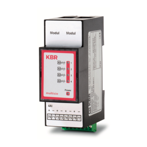
KBR multisio 1D4-4RO ISO User manual

Operating Instructions
Technical Parameters
Potential free
4 relay output module
1D4-4RO ISO
multisio

Operating instructions multisio 1D4-4RO ISO
Page 1 of 1 Version 2.00
EDEBDA0187 / 1511-1 GB
Table of Contents
1 Function description relay output module
multisio 1D4-4RO ISO ...........................................................................2
2 Connection diagram for relay output module .....................................2
3 Relay output module LED display .......................................................3
4 Function of scan button ........................................................................3
5 Function of the DIP switches ...............................................................4
5.1 Mode of operation .................................................................................................4
5.2 DIP switch settings ...............................................................................................4
6 Technical data ........................................................................................5

Operating instructions multisio 1D4-4RO ISO
Version 2.00 Page 2 of 5
EDEBDA0187 / 1511-1 GB
1 Function description relay output module
multisio 1D4-4RO ISO
The hardware of the multisio 1D4-4RO ISO supports 4 potential free relay outputs, 5 LEDs and an 8-fold DIP
switch.
The relay outputs serve to control contactors of bus devices or other systems.
The module can be accessed via a master device (multimax 3D6, multisio 5D6 or higher, or a computer with
VE via multisys 3D2-ESBS) using the module bus interface. The master device has to configure the module.
The operating voltage is supplied via the module bus interface. The module cannot be used on its own.
2 Connection diagram for relay output module
Terminal assignment
Terminal 40: Input relay 1 (A1)
Terminal 41: Output relay 1 (A1)
Terminal 42: Input relay 2 (A2)
Terminal 43: Output relay 2 (A2)
Terminal 44: Input relay 3 (A3)
Terminal 45: Output relay 3 (A3)
Terminal 46: Input relay 4 (A4)
Terminal 47: Output relay 4 (A4)
IN / OUT: Module bus / supply voltage
bNote
The module relay outputs are designed as potential free outputs.

Operating instructions multisio 1D4-4RO ISO
Page 3 of 5 Version 2.00
EDEBDA0187 / 1511-1 GB
3 Relay output module LED display
In KBR module bus scanning mode, all 4 output LEDs are flashing.
In module detection mode, the output LEDs generate a running light.
The displays are:
4 Function of scan button
LED1 for: Output relay 1 (A1) switched
LED2 for: Output relay 2 (A2) switched
LED3 for: Output relay 3 (A3) switched
LED4 for: Output relay 4 (A4) switched
Power LED: Operating voltage
bNote
If the scan button is pressed briefly, the module enters the scanning mode.
Switch setting illustrated:
OFF = white
ON = gray

Operating instructions multisio 1D4-4RO ISO
Version 2.00 Page 4 of 5
EDEBDA0187 / 1511-1 GB
5 Function of the DIP switches
5.1 Mode of operation
• DIP switch 5 determines the operating mode of output 1
• DIP switch 6 determines the operating mode of output 2
• DIP switch 7 determines the operating mode of output 3
• DIP switch 8 determines the operating mode of output 4
If the DIP switch is set to Off, the respective output is in the normal operating
mode. If the DIP switch is set to On, the respective output is in the manual
operating mode.
Switch setting illustrated:
Normal operating mode
In the normal operating mode, the state created in the module is issued at the corresponding output.
Manual operating mode
In the manual operating mode, the state of DIP switches 1 to 4 is issued at the corresponding output, instead
of the state created in the module. The DIP switches are assigned to the outputs as follows:
• DIP switch 1 determines the state of output 1
• DIP switch 2 determines the state of output 2
• DIP switch 3 determines the state of output 3
• DIP switch 4 determines the state of output 4
If the DIP switch is set to Off, the output is passive / off. If the DIP switch is set to On, the output is active / on.
5.2 DIP switch settings
For every output, the multisio 1D4-4RO ISO differentiates between the
operating modes "normal" and "manual". Switching is performed via the DIP
switches 5 to 8.
The DIP switches are assigned to the outputs as follows:
OFF = white
ON = gray
Mode of
operation
State
DIP
Explanation
S5
Off --- --- Output 1 = normal operating mode
On S1 Off Output 1 = manual operating mode passive / off
On Output 1 = manual operating mode active / on
S6 Off --- --- Output 2 = normal operating mode
On S2 Off Output 2 = manual operating mode passive / off
On Output 2 = manual operating mode active / on
S7
Off --- --- Output 3 = normal operating mode
On S3 Off Output 3 = manual operating mode passive / off
On Output 3 = manual operating mode active / on
S8
Off --- --- Output 4 = normal operating mode
On S4 Off Output 4 = manual operating mode passive / off
On Output 4 = manual operating mode active / on

Operating instructions multisio 1D4-4RO ISO
Page 5 of 5 Version 2.00
EDEBDA0187 / 1511-1 GB
6 Technical data
Power supply: Via module bus 24VDC / ca. 1.3W
Connection Modular connector RJ-12:6P6C
Hardware outputs: 4 plug terminal, each 2 pole
4 relay outputs Terminals 40 to 47 potential free
Contact capacity 500VA each, 2A, 250V and 50/60Hz
Overvoltage category CAT II
Module bus interface: Serial interface RS-485
Module bus connection RJ-12 for ready-made
KBR system cable, max. length 30 m
when placed accordingly
Transmission speed 38400 Bps
Bus protocol KBR module bus
Display: LED 4x message
1x operation display
Control unit DIP switch 1x 8-fold, for manual operation
Button Scan button (module bus)
Mechanical data:
Top hat rail device Housing measurements 90 x 70 x 61 mm (H x W x D)
Mounting type Wall mounting on DIN rail
7.5 mm deep, in accordance with
DIN EN 50022.
Weight approx. 130g
Standards and
miscellaneous:
Ambient conditions Standards DIN EN 60721-3-3/A2: 1997-07;
3K5+3Z11; (IEC721-3-3; 3K5+3Z11)
Operating temperature -5°C ... +55°C
Humidity 5% ... 95%, non-condensing
Storage temperature -25°C ... +70°C
Electrical safety Standards DIN EN 61010-1/A2: 2001 + B1:
2002-11 + B2: 2004-1;
(IEC1010-1/A2)
Mode of protection IP20 in accordance with DIN EN
40050
part 9:1993-05
Electromagnetic
compatibility DIN EN 61000-6-3: 2001 + A11:
2004; (IEC61000-6-3)
DIN EN 61000-6-2: 2001
(IEC61000-6-2)

ERKLÄRUNG DER KONFORMITÄT
DECLARATION OF CONFORMITY
DÉCLARATION DE CONFORMITÉ
Wir
We/Nous (Name des Anbieters / supplier´s name / norm du fournisseur)
KBR GmbH Schwabach
(Anschrift / address / addresse)
Am Kiefernschlag 7
D-91126 Schwabach
erklären in alleiniger Verantwortung, dass das (die) Produkt(e) /
declare under our sole responsibility that the product(s) / Déclarons sous notre seule responsabilité, ques le(s) produit(s)
(Bezeichnung, Typ oder Modell oder Seriennummer / name, type or model or serial number / nom, type ou modèle, N° de lot ou de série)
multisio 1D4-4RO ISO
mit folgenden Europäischen Richtlinien übereinstimmt (übereinstimmen)
is (are) in conformity with the following directives / Répondet(ent) aux directives suivantes
Dies wird nachgewiesen durch die Einhaltung folgender Norm(en)
This is documented by the accordance with the following standard(s) / Justifié par le respect de la (des) norme(s) suivante(s)
DIN EN 61010-1-2001; DIN EN 61010-1/B1:2002
DIN EN 61010-1/B2:2004
DIN EN 61000-6-1:2007
DIN EN 61000-6-2:2005
DIN EN 61000-6-3:2007
DIN EN 61000-6-4:2007
(Titel und/oder Nr. sowie Ausgabedatum der Norm(en)
Title and/or number and date of issue of the standard(s)
Titre et/ou numéro et date d´édition de la (des) norme(s)
Schwabach, 11.04.2011
(Ort und Datum der Ausstellung
Place and date of issue
Lieu et date de l´édition)
Geschäftsführer
General manager
© KBR GmbH Konformitätserklärung Elektronik EDENOR0002_1311-1_DE_EN_FR
Niederspannungsrichtline Nr.
Low Voltage Directive No.
Directive Basse Tension N°
EMV-Richtlinie Nr.
EMV Directive No.
EMV Directive N°
2006/95/EG
2006/95/EC
2006/95/CE
2004/108/EG
2004/108/EC
2004/108/CE
KBR GmbH Am Kiefernschlag 7 D-91126 Schwabach T +49 (0) 9122 6373-0 F +49 (0) 9122 6373-83 E info@kbr.de www.kbr.de

1309-1 DE / GB
An To
KBR GmbH KBR GmbH
Abteilung Entwicklung Development
Am Kiefernschlag 7 Am Kiefernschlag 7
D-91126 Schwabach D-91126 Schwabach / Germany
Vorschläge:
Korrekturen:
Betrifft Gerät:
Suggestions:
Corrections:
Device concerned
Sollten Sie beim Lesen dieser Bedienungsanleitung oder
Druckschrift auf Druckfehler gestoßen sein, bitten wir
Sie, uns diese mitzuteilen. Ebenso freuen wir uns natür-
lich über Anregungen, Hinweise oder Verbesserungsvor-
schläge.
Bitte geben Sie die betreffende Anleitung oder Druck-
schrift mit Versionsnummer und/oder Ausgabestand an.
If you come across misprints in this user manual or prin-
ted material, please take the time to notify us. We will
also be glad to hear your ideas, notes and suggestions for
improvement.
Please identify the user manual or printed material in
question with version number and/or revision number.
Absender / Sender:
Name:
Firma/Dienststelle, / Copany/Department:
Anschrift / Address:
Telefon / Phone:
Telefax / Fax:
email:
Korrekturvorschläge zur Bedienungsanleitung / Druck-
schrift
Corrections/Suggestions for user manual / Printed mate-
rial
Version
Table of contents
Other KBR Control Unit manuals
Popular Control Unit manuals by other brands

Polycom
Polycom RMX DOC2579D Getting started guide

Fasel Elektronik
Fasel Elektronik FCU6x00 Series Installation and operating manual

Bosch
Bosch PAVIRO PVA-1WEOL Installation note

GF
GF 369 operating instructions

National Instruments
National Instruments 7340 PCI user manual

Advantech
Advantech PCM-3524 user manual