KBR multisio D2-4AI-2 User manual

22070_EDEBDA0241-3617-1_EN
User manual
Technical parameters
Your partner for
network analysis
Module with
4 analog inputs
D2-4AI-2
multisio
System IEnglisch
Your partner for
D2-4AI-2

Rev. 2.01
22070_EDEBDA0241-3617-1_EN
2
KBR multisio D2-4AI-2 Introduction
Dear customer
Thank you for choosing a KBR product.
To familiarize yourself with the operation and conguration of the device, we recommend
that you read this manual carefully. This way, you will be able to use of the entire range of
functions that this high-quality product has to oer.
The individual chapters explain the technical details of the device and show how to
properly install and start it up to prevent damage.
This user manual is included in the scope of delivery of the device and must be accessible
to the user at all times (e.g. in the switchgear cabinet). Even if the device is resold to third
parties, the manual remains an inherent part of the device.
Although the utmost care has been taken in putting together this user manual, errors
may still occur. We would be very grateful if you could notify us of any errors or unclear
descriptions you may notice. The form included in the appendix to this manual can be
used to send us corrections or suggested improvements.
Yours sincerely,
KBR GmbH Schwabach

Rev. 2.01
22070_EDEBDA0241-3617-1_EN
3
KBR multisio D2-4AI-2Introduction
This user manual contains notes that you have to observe for your personal
safety and to prevent damage to the equipment. These notes are identied by
a warning sign or information symbol, depending on the degree of hazard they
warn about.
DANGEROUS VOLTAGE
means that death, major injury or substantial property damage may occur if the
appropriate safety measures are not taken.
CAUTION
means that minor injuries or property damage may occur if the appropriate
safety precautions are not taken.
NOTE
is an important piece of information on the product, product handling or the
respective part of the user manual to which special reference is made.
Disclaimer
The contents of this manual have been checked to concur with the described
hardware and software components. However, deviations may occur, meaning
that no guarantee can be made for complete agreement with the documen-
tation. The specications given in this manual are checked on a regular basis;
necessary corrections will be included in the next revision.
We appreciate your corrections and comments.
Safety notes
In order to prevent operating errors, handling of the device has been kept as
simple as possible. This will enable you to use the device very quickly. In your
own interest, however, read the following safety notes carefully.

Rev. 2.01
22070_EDEBDA0241-3617-1_EN
4
KBR multisio D2-4AI-2 Introduction
Product liability
You have purchased a high-quality product.
Only components of the highest quality and maximum reliability are used.
Each device is subject to long-term testing before it is delivered. For details on
product liability, please refer to our general terms and conditions for electronic
equipment.
The warranty on device properties applies only if the device has been operated
in accordance with its intended use!
Disposal
Devices that are faulty, obsolete or no longer used must be properly
disposed of.
If required, we will dispose of the devices for you.
Scope of delivery
Included in the scope of delivery:
Analog input module
Connector set
User manual
2 Installing the device
The housing of the transducer attachment is designed for mounting in the
cabinet to 35 mm standard rail. The module is snapped on the standard rail.

Rev. 2.01
22070_EDEBDA0241-3617-1_EN
5
KBR multisio D2-4AI-2
2 Description of functions
multisio D2-4AI-2 analog input module
The hardware of the multisio D2-4AI-2 supports four analog inputs and ve
LEDs.
With its four analog measuring inputs, it can measure currents from 0 to 20 mA
and voltages from 0 to 10 V.
The four input LEDs indicate the state of the analog inputs and the power LED
indicates whether the power is on or o.
The module can be accessed by a master device (multisio D6...x (D6-ESBS-5DI-
6RO-1DO-5 or higher) with module bus or a computer with VE using multisys
D2-ESBS-3 / multisys D2- BSES-3) via the module bus interface.
The master device has to congure the module and read out the data acquired
by the module for further processing.
The operating voltage is supplied via the module bus interface. The module
cannot be used on its own.
3 Analog input module connection diagram
Terminal assignment
Terminal 70: Analog input 1 +
Terminal 71: Analog input 1 -
Terminal 72: Analog input 2 +
Terminal 73: Analog input 2 -
Terminal 74: Analog input 3 +
Terminal 75: Analog input 3 -
Terminal 76: Analog input 4 +
Terminal 77: Analog input 4 -
IN/OUT: Module bus/power supply
multisio D2-4AI-2
70 71 72 73 74 75 76 77
+−+−+−+−
IN OUT
Module
Modul
Module
Modul
Rev. 2.01
22070_EDEBDA0241-3617-1_EN
6
KBR multisio D2-4AI-2
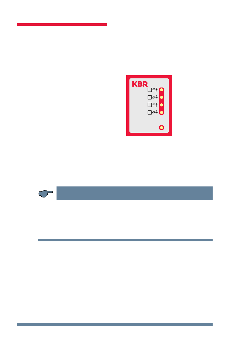
4 Analog input module LED display
In the scan mode of the KBR module bus, all 4 input LEDs ash.
In module detection mode, the input LEDs ash in sequence.
The LEDs represent:
LED1 for input 1
LED2 for input 2
LED3 for input 3
LED4 for input 4
Power LED on:
Operating voltage
is applied
The LEDs on the module with 4 digital inputs turn on when an analog input
signal is detected and the measured values are within the set limits.
The LEDs go out if no analog encoder is connected or if the encoder is short-
circuited. The LEDs ash if the value exceeds or falls below a limit.
NOTE
For operation at the multisio D6...x (D6-ESBS-5DI6RO1DO-5 and higher) base
device, the module is always set up for 0-20 mA/0-10 V, meaning that the LEDs
of inputs 1-4 are always on.
The multisio D6...x base device makes the conversion to 4-20 mA/2-10 V.
1
2
3
4
Power
AI
AI
AI
AI
multisio

Rev. 2.01
22070_EDEBDA0241-3617-1_EN
7
KBR multisio D2-4AI-2
5 Scan button function
NOTE
If the scan button is pressed briey,
the module enters the scan mode.
Illustrated switch setting:
OFF = white
ON = gray
6 DIP switch function
Switching inputs 1 to 4:
Switch set to
OFF:
Switch set to
ON:
S1 = 0 / 2 – 10V S1 = 0 / 4 – 20mA
S2 = 0 / 2 – 10V S2 = 0 / 4 – 20mA
S3 = 0 / 2 – 10V S3 = 0 / 4 – 20mA
S4 = 0 / 2 – 10V S4 = 0 / 4 – 20mA
Scan-Button
Scan-Taster
DIP-Switch
DIP-Schalter
ON SAB
1234
ON SAB
1234

Rev. 2.01
22070_EDEBDA0241-3617-1_EN
8
KBR multisio D2-4AI-2
7 Technical data:
Power supply: Via module bus 24 V DC/approx. 1.3W
Connection Modular connector
RJ-12:6P6C
Hardware inputs:
4 analog inputs: Measuring range 0/4 - 20 mA, 0/2 - 10 V
Plug-in terminal, 8-pin
Module bus interface: Serial interface RS-485
Module bus connection RJ-12 for ready-made
KBR system cable,
max. length 30 m if
correctly placed
Transmission speed 38400 Bps
Bus protocol KBR module bus
Display: LED 4x message
1x operation display
Control unit: DIP switch Conguration with
4 inputs
Button Scan button
(module bus)
Mechanical data:
DIN rail device: Housing dimensions 90 x 36 x 61 mm
(H x W x D)
Mounting type Wall mounting on
7.5 mm deep DIN rail,
in accordance with
DIN EN 50022.
Suitable for distribution
board mounting
Weight Approx. 100 g

Rev. 2.01
22070_EDEBDA0241-3617-1_EN
9
KBR multisio D2-4AI-2
Ambient conditions / electrical safety
Ambient
conditions
Standards DIN EN 60721-3-3/A2: 1997-07;
3K5+3Z11; (IEC721-3-3; 3K5+3Z11)
Operating tempe-
rature
K55 (-5°C …. +55°C)
Humidity 5 % … 95 %, non-condensing
Storage tempera-
ture
K55 (-25°C …. +70°C)
Operating altitude 0 to 2000 m above sea level
Electrical
safety (used
with base
device)
Standards
DIN EN 61010-1: 2011-07
Protection class I
Overvoltage cate-
gory
CAT III
Rated surge voltage 4kV
Protection
type
Standards IP20 in accordance with DIN EN 60529:
EMC Standards DIN EN 61000-6-2:2006-03 +
amendment 1:2011-03
DIN EN 61000-6-3:2011-09 +
amendment 1:2012-11
DIN EN 61326-1:2013-07

Rev. 2.01
Notes
22070_EDEBDA0241-3617-1_EN
KBR multisio D2-4AI-2
Table of contents
Other KBR Control Unit manuals

Popular Control Unit manuals by other brands

Festo
Festo Compact Performance CP-FB6-E Brief description

Elo TouchSystems
Elo TouchSystems DMS-SA19P-EXTME Quick installation guide

JS Automation
JS Automation MPC3034A user manual

JAUDT
JAUDT SW GII 6406 Series Translation of the original operating instructions

Spektrum
Spektrum Air Module System manual

BOC Edwards
BOC Edwards Q Series instruction manual

KHADAS
KHADAS BT Magic quick start

Etherma
Etherma eNEXHO-IL Assembly and operating instructions

PMFoundations
PMFoundations Attenuverter Assembly guide

GEA
GEA VARIVENT Operating instruction

Walther Systemtechnik
Walther Systemtechnik VMS-05 Assembly instructions

Altronix
Altronix LINQ8PD Installation and programming manual


