8
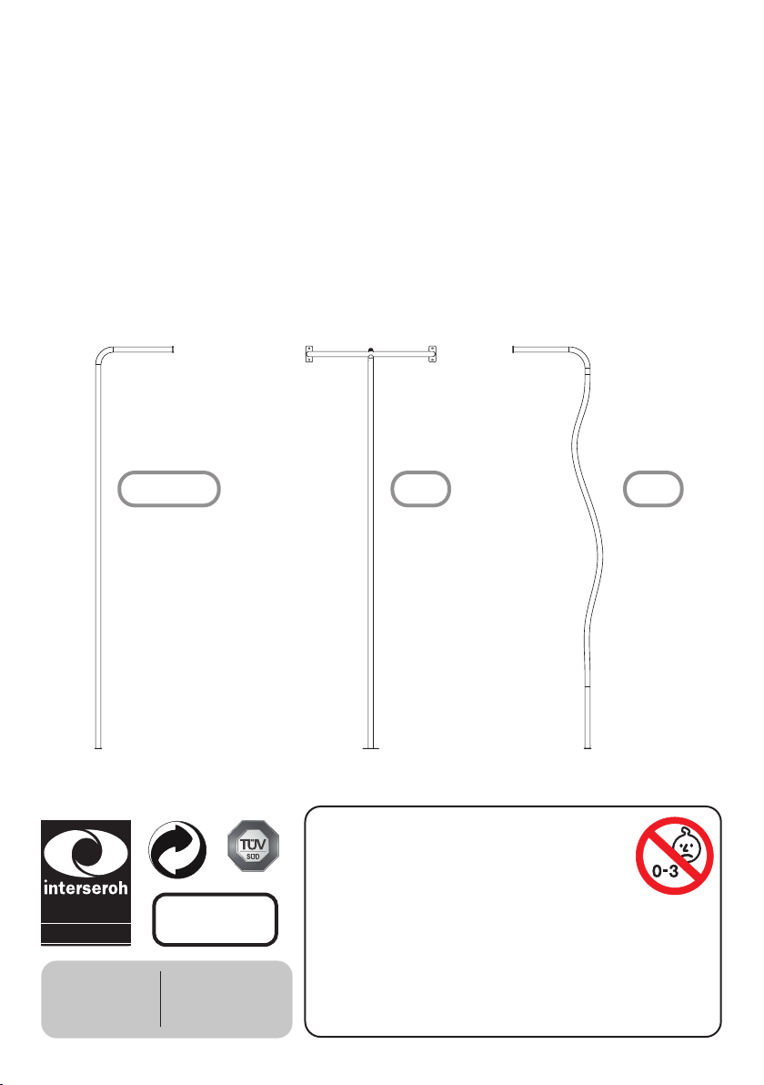
Instructions for use - M34x.01 - metal reman’s pole Type-L, Type-T, Wiggle
INSTRUKCJA UŻYTKOWANIA PL
INSTRUKCJA BEZPIECZEŃSTWA
1. Prosimy zachować niniejszą instrukcję użytkowania w celu wykorzystania jej w przyszłości.
2. Prosimy nie modykować urządzenia ani sposobu montażu w jakikolwiek sposób. Zmiany będą miały wpływ na in-
tegralność struktury i wymiana części zamiennych nastąpi na koszt nabywcy. Niewłaściwe użytkowanie lub zasto-
sowanie produktu niezgodne z przeznaczeniem jest zabronione i zwalnia producenta z jakiejkolwiek odpowiedzial-
ności. Przed użyciem produkt musi być zmontowany i sprawdzony przez osobę dorosłą.
3. Korzystanie tylko pod stałym nadzorem osoby dorosłej. Produkt przeznaczony jest dla osób o wadze do 100 kg.
Produkt nie nadaje się dla dzieci w wieku poniżej 36 miesięcy, ze względu na brak dodatkowych zabezpieczeń i
typowy dla małych dzieci brak umiejętności przewidywania. Ryzyko upadku!
4. Ten produkt jest odpowiedni do użytku komercyjnego i zgodny z europejską normą bezpieczeństwa EN 1176-
1:2017.
5. Podczas montowania produktu należy upewnić się, czy nie występuje ryzyko zakleszczenia.
6. Produkt musi być zamontowany w taki sposób, aby wysokość upadku ograniczona była do 2,5 m. Wysokość mie-
rzona od podłoża do najwyższego punktu na które dziecko może usiąść, wspiąć się lub stanąć.
7. Słupy strażackie, do których można uzyskać dostęp przez platformę lub inny punkt startowy, muszą mieć co najm-
niej 350 mm prześwit od słupa do krawędzi przylegającej konstrukcji. Ma to umożliwić bezpieczne chwytanie słupa
przy jednoczesnym zmniejszeniu ryzyka uderzenia głową o sąsiednią konstrukcję. Ponieważ użytkownik może być
zawieszony na poziomej i pionowej części słupa strażackiego, musi istnieć wolna przestrzeń dla użytkownika o
promieniu 50 cm od wysokości 30 cm nad słupem strażackim do powierzchni uderzenia poniżej.
8. Podczas montowania lub składania urządzenia, należy przestrzegać minimalnej wymaganej odległości między urzą-
dzeniem a ewentualnymi przeszkodami: ścianami, ogrodzeniem itp. Wolna przestrzeń musi być wolna od przesz-
kód, które utrudniają przejście użytkownika podczas zjeżdżania ze słupa, np. gałęzi drzew, lin, belek poprzecznych
itp. W wolnej przestrzeni powinny znajdować się części sprzętu, na których znajduje się użytkownik, które go
mieszczą lub pomagają mu w utrzymaniu równowagi, np. platforma.
9. Dimension of the impact area depends on the free height of fall (FIG I). The impact area shall be at least 1,5 Wymiar
obszaru uderzenia zależy od swobodnej wysokości upadku (RYS. I). Obszar uderzenia musi wynosić co najmniej 1,5
m wokół sprzętu, mierzony poziomo. Musi się również zwiększać do wysokości swobodnego upadku powyżej 1,5 m.
W tym obszarze bezpieczeństwa nie powinny znajdować się żadne twarde, kanciaste lub spiczaste przedmioty (RYS.
II). Bezpieczna powierzchnia pod produktem musi być płaska i pokryta w odpowiedni sposób (np. płytkami gu-
mowymi, korą, zrębkami) oraz spełniać wymagania normy EN 1176-1:2017.
10. Przestrzeń spadania równa się powierzchni obszaru uderzenia o wysokości 250 cm. W tym obszarze bezpieczeństwa
nie powinny znajdować się żadne twarde, kanciaste lub spiczaste przedmioty.
11. Regularna kontrola produktu, jest gwarancją bezpieczeństwa. W przypadku wymiany lub zapotrzebowania na
więcej produktów należy skontaktować się z dostawcą.
12. Po montażu, należy upewnić się, czy produkt zamatowany jest idealnie poziomo.
KONTROLA I KONSERWACJA
Częstotliwość kontroli i konserwacji zależy od rodzaju artykułu, użytych materiałów bądź innych czynników (np. dużego
obciążenia, umyślnego zniszczenia, wilgotności powietrza, zanieczyszczenia powietrza, wieku wyposażenia itp.).
Części zamienne powinny być zgodne ze specykacją KBT. Należy sprawdzać stan nawierzchni amortyzującej upadek, a
w szczególności poziom sypkich materiałów wypełniających.
Rutynowa kontrola (raz na tydzień lub raz na miesiąc)
- Zawsze należy sprawdzać, czy śruby i nakrętki są mocno dokręcone.
- Na podłożu amortyzującym pod produktem nie powinny znajdować się żadne przedmioty.
- Należy sprawdzać, czy nie brakuje żadnych elementów.
- Należy sprawdzać czy na podłożu nie znajdują się niebezpieczne przedmioty.
Kontrola robocza (raz na 1 do 3 miesięcy)
- Należy sprawdzać stabilność konstrukcji.
- Należy sprawdzać zużycie każdej części i w razie potrzeby wymienić na nową.
Kontrola roczna (1 lub 2 razy do roku)
- Należy sprawdzać elementy konstrukcji pod kątem obecności rdzy i korozji.
- Należy sprawdzać zużycie każdej części i w razie potrzeby wymienić na nową.
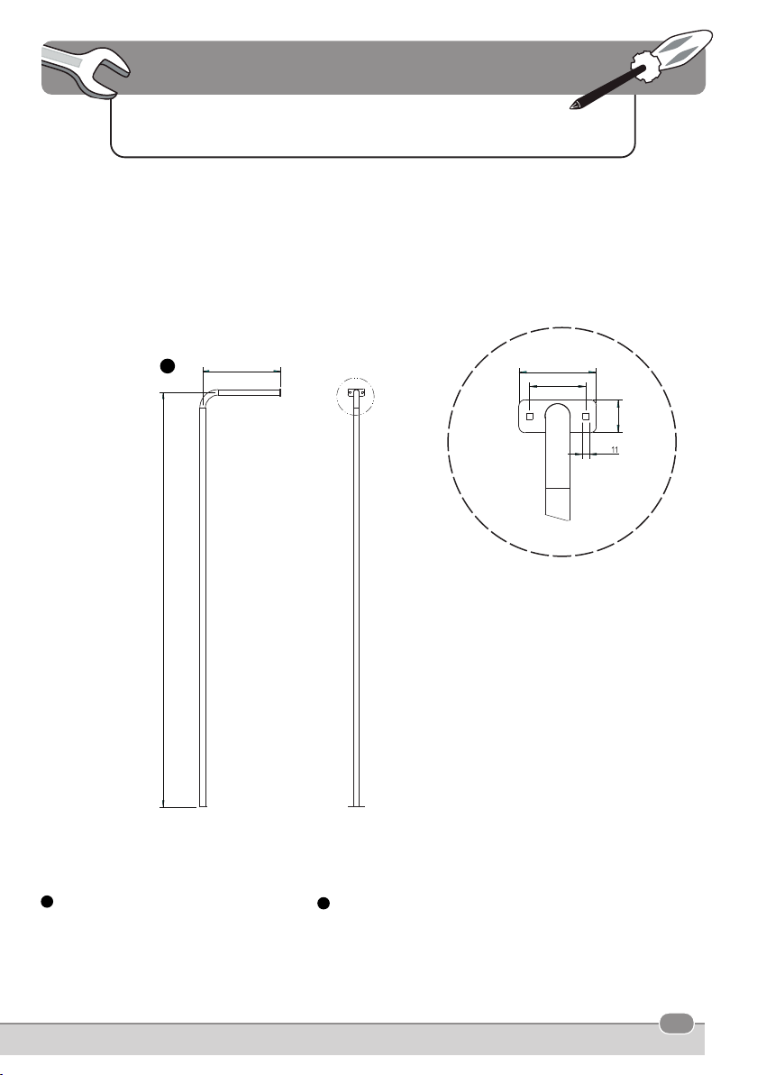
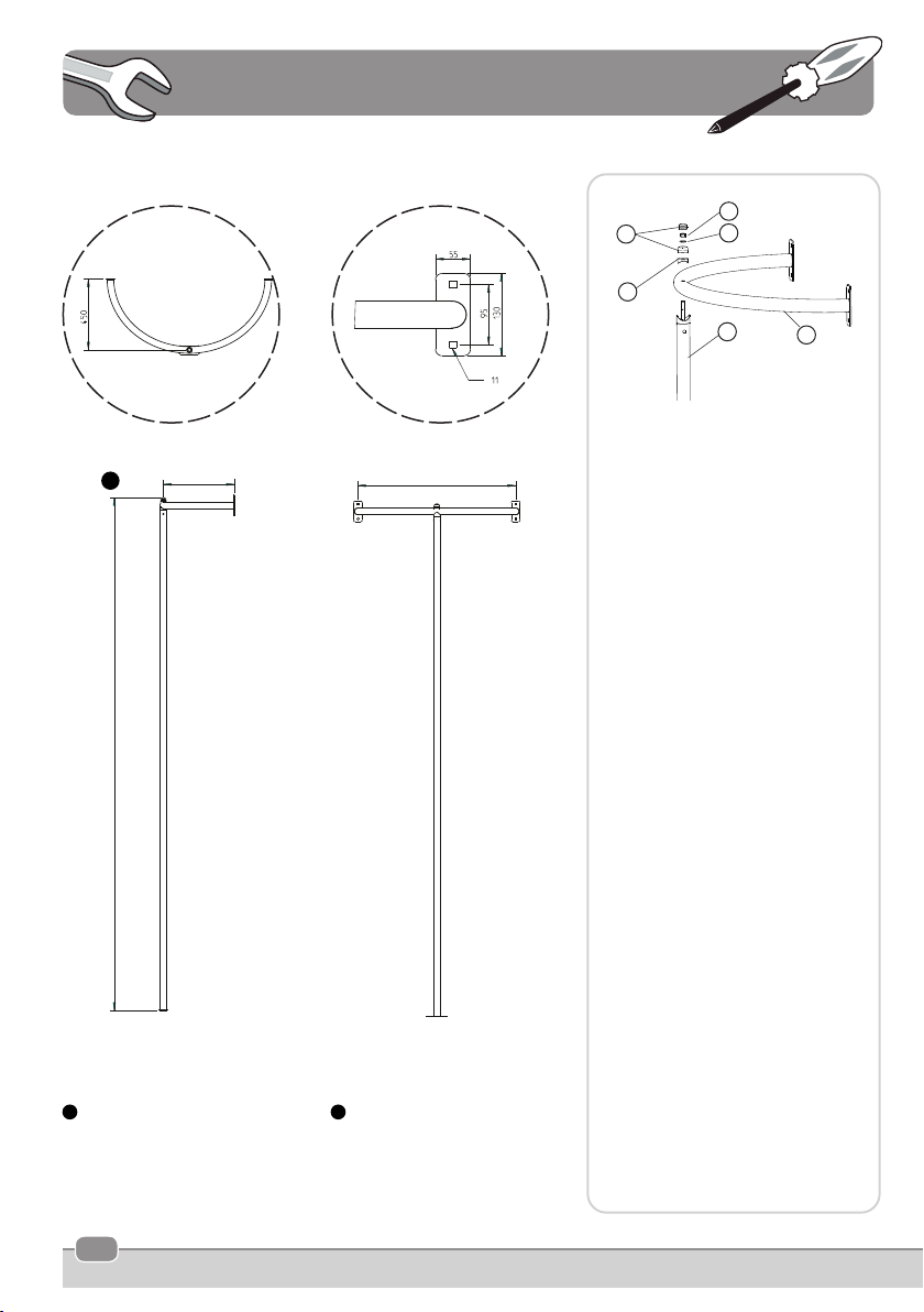
metalowa rura strażacka
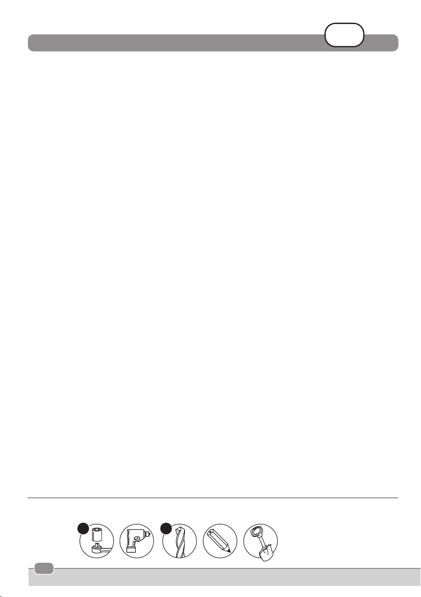
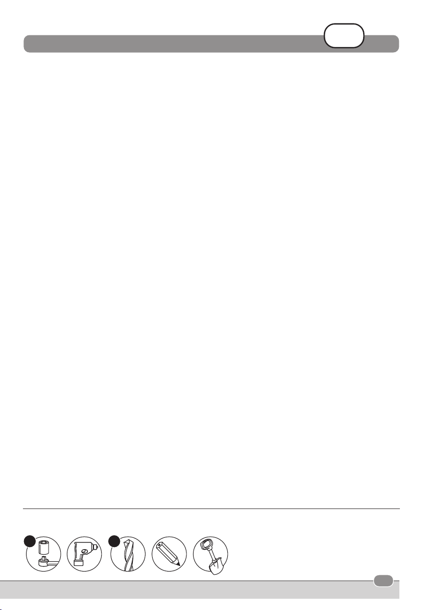
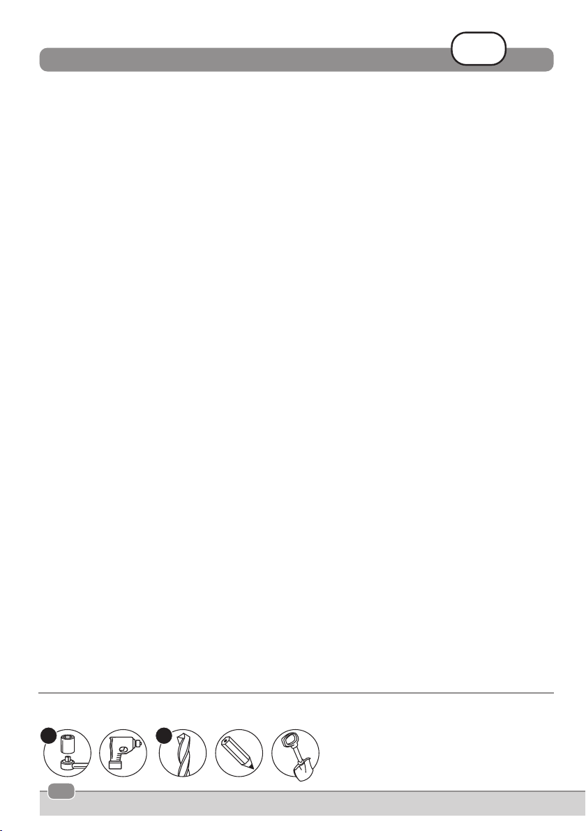
(1) klucz z grzechotką i nakładką 17
(2) wiertarka
(3) wiertło do wiertarki o średnicy 11 mm
(4) ołówek
(4) łopata
NARZĘDZIA
17
(1) (2)
11
(3) (4) (5)