1. General
The FlexBalance EcoPlus C, including PU insulation, creates hydraulic balance between the
primary circuit and the secondary circuit and has four ports, a Flexvent Top automatic airvent with
valve sleeve and drain cock.
Furthermore, the FlexBalance EcoPlus C can also be used as an air and dirt separator and it is
suitable for use in sealed heating or cooling systems using glycol-based additives (max. 50%).
• Minimum and maximum system temperature: -10 °C up to + 110 °C.
• Minimum and maximum operating pressure: 0.2 bar up to 10 bar.
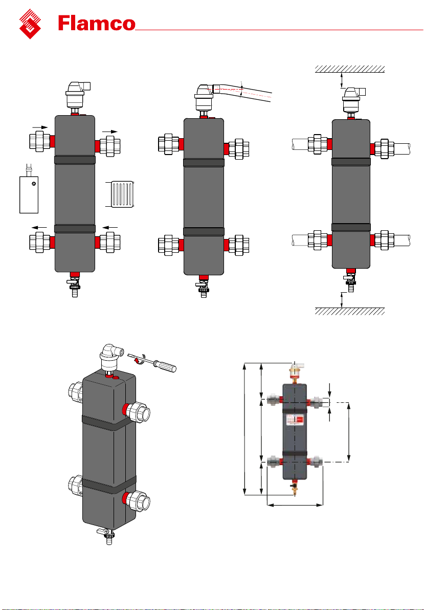
Model Dimensions (mm)
A B C D E F G
FlexBalance EcoPlus C 1" DN25 160 290 170 620 276 262
FlexBalance EcoPlus C 1 1/4"DN32 160 340 180 680 321 280
FlexBalance EcoPlus C 1 1/2"DN40 160 340 180 680 320 320
FlexBalance EcoPlus C 2" DN50 170 400 185 755 373 326
2. Installation
Following the points below will ensure that the FlexBalance EcoPlus C works properly.
• Make sure installation is carried out by qualifi ed personnel.
• Observe local legislation and guidelines.
• The FlexBalance EcoPlus C must be connected directly to the boiler(s) on the supply pipe and
the return pipe (see fi g. 1).
• See the table for the connection dimensions.
• To facilitate maintenance work/servicing, there must be clearance (see fi g. 3) of at least 50 mm (S)
above the vent, whilst below the drain cock there must be clearance of at least 150 mm (G).
• For optimum operating conditions, we recommend a fl ow rate of 1.2 m/s
(functional maximum 3 m/s) in the supply pipe.
• Install the FlexBalance EcoPlus C only after the pipes have been properly fl ushed and pressure
tested.
• The FlexBalance EcoPlus C must be installed vertically.
• In order to install the FlexBalance EcoPlus C with the minimum of fuss, remove the insulation by
detaching the Velcro.
• Use sealing tape between the connections of pre-mounted coupling and between the drain cock
and the valve sleeve of the vent.
• If available, slide the temperature sensor (next to the vent connection) as deep as possible into
the tube (internal diameter ø12).
• When doing this, use enough conductive paste to ensure good heat conduction.
•Install the vent in the valve sleeve.
• The valve end of the vent measures 22 mm (external); an air-discharge hose can easily be
attached. It must be attached in a downward arc (see fi g. 2).
•Reapply insulation.
1. General
The FlexBalance EcoPlus C, including PU insulation, creates hydraulic balance between the
primary circuit and the secondary circuit and has four ports, a Flexvent Top automatic airvent with
valve sleeve and drain cock.
Furthermore, the FlexBalance EcoPlus C can also be used as an air and dirt separator and it is
suitable for use in sealed heating or cooling systems using glycol-based additives (max. 50%).
• Minimum and maximum system temperature: -10 °C up to + 110 °C.
• Minimum and maximum operating pressure: 0.2 bar up to 10 bar.
Model Dimensions (mm)
A B C D E F G
FlexBalance EcoPlus C 1" DN25 160 290 170 620 276 262
FlexBalance EcoPlus C 1 1/4"DN32 160 340 180 680 321 280
FlexBalance EcoPlus C 1 1/2"DN40 160 340 180 680 320 320
FlexBalance EcoPlus C 2" DN50 170 400 185 755 373 326
2. Installation
Following the points below will ensure that the FlexBalance EcoPlus C works properly.
• Make sure installation is carried out by qualified personnel.
• Observe local legislation and guidelines.
• The FlexBalance EcoPlus C must be connected directly to the boiler(s) on the supply pipe and
the return pipe (see fig. 1).
• See the table for the connection dimensions.
• To facilitate maintenance work/servicing, there must be clearance (see fig. 3) of at least 50 mm (S)
above the vent, whilst below the drain cock there must be clearance of at least 150 mm (G).
• For optimum operating conditions, we recommend a flow rate of 1.2 m/s
(functional maximum 3 m/s) in the supply pipe.
• Install the FlexBalance EcoPlus C only after the pipes have been properly flushed and pressure
tested.
• The FlexBalance EcoPlus C must be installed vertically.
• In order to install the FlexBalance EcoPlus C with the minimum of fuss, remove the insulation by
detaching the Velcro.
• Use sealing tape between the connections of pre-mounted coupling and between the drain cock
and the valve sleeve of the vent.
• If available, slide the temperature sensor (next to the vent connection) as deep as possible into
the tube (internal diameter ø12).
• When doing this, use enough conductive paste to ensure good heat conduction.
•Install the vent in the valve sleeve.
• The valve end of the vent measures 22 mm (external); an air-discharge hose can easily be
attached. It must be attached in a downward arc (see fig. 2).
•Reapply insulation.
3. Maintenance and service
Carry out regular inspection (for the presence of dirt and such like).
In the unlikely event of a leak in the vent, it can be closed with the screw (see fig. 4).
The drain cock is used to discharge the sludge that collects in the FlexBalance EcoPlus C.
Attention!
Prevent dirt from the system getting into the Flexvent vent, water shock in the system and direct
contact with chlorine bleach and other such products (at concentrations of ≥ 250 ppm).
Water treatment products may be used on condition that the manufacturer guarantees that the
product in question is suitable for all materials with which it may come into contact in the system.
4. Dismantling
The system must be completely cool before any servicing work is performed.
de-pressurize all pipework (not necessary if the Flexvent Top vent is merely unscrewed from the
valve sleeve).
Disconnect the couplings prior to dismantling.
Environment
Observe local legislation and regulations when disposing of the FlexBalance EcoPlus C.
Produced is in compliance with the terms of the European Pressure Equipment Directive
97/23/EC.
(See also www.flamcogroup.com)