KEBCO COMBIVERT S6 Series User manual

COMBIVERT
GB Installation Manual F6 with Safety Function STO
Control Circuit
Translation of original manual
Document Part Version Date
20094313 GBR 00 1014


GB - 3
Table of Contents
1. Preface..............................................................................................................5
1.1 General ................................................................................................................................. 5
1.2 Safety Instructions .............................................................................................................. 5
1.3 Validity and liability ............................................................................................................. 5
1.4 Copyright.............................................................................................................................. 6
1.5 Speciedapplication........................................................................................................... 6
1.6 Product description............................................................................................................. 6
2. Control..............................................................................................................8
2.1 Features of the control........................................................................................................ 8
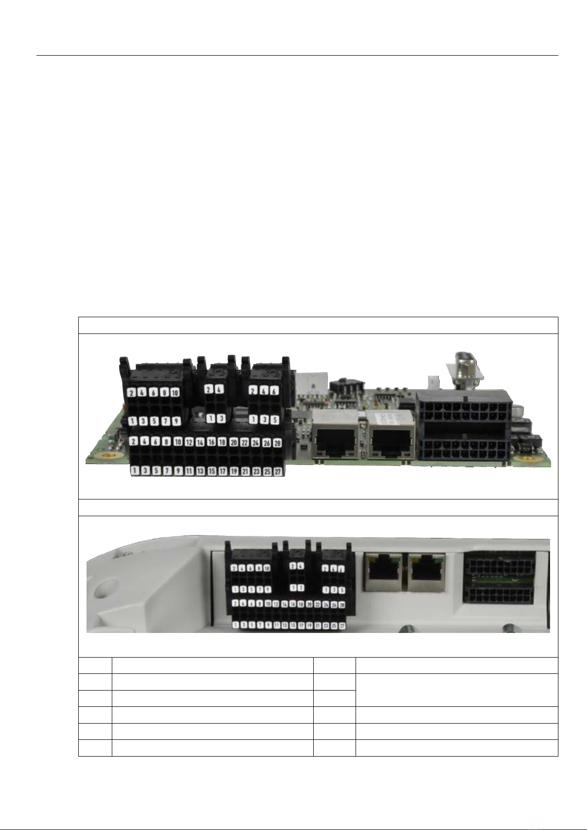
2.2 Overview............................................................................................................................... 8
2.2.1 Control terminal strip X2A...................................................................................................... 9
2.2.2 Safety terminal block X2B...................................................................................................... 9
2.2.3 CAN terminal block X2C ........................................................................................................ 9
2.2.4 Analog inputs X2D ................................................................................................................ 9
2.2.5 Diagnostic interface X4A........................................................................................................ 9
2.2.6 Encoder interfaces X3A, X3B ................................................................................................ 9
2.3 Connection of the control ................................................................................................. 10
2.3.1 Assembly of the wires.......................................................................................................... 10
2.4 Assignment of the terminal strip X2A...............................................................................11
2.4.1 Connection of the digital inputs............................................................................................ 12
2.4.2 Connection of the digital outputs ......................................................................................... 12
2.5 Assignment of the STO terminal strip X2B ..................................................................... 13
2.5.1 Inputs ................................................................................................................................... 13
2.5.1.1 SpecicationoftheSTOinputs ........................................................................................... 13
2.5.1.2 STOwithOSSDsignals....................................................................................................... 13
2.5.2 OutputSTO.......................................................................................................................... 13
2.6 Assignment of the CAN terminal strip X2C..................................................................... 14
2.7 Assignment of the terminal strip for analog inputs X2D ............................................... 14
2.7.1 Connection of the analog inputs .......................................................................................... 14
2.7.2 Diagnosis/visualisation ........................................................................................................ 15
2.7.2.1 Assignment of the interface X4A.......................................................................................... 15
2.7.2.2 Connection of the RS232 interface...................................................................................... 15
2.7.2.3 Connection of the RS485 interface...................................................................................... 15
2.7.2.4 Wiring RS485 full duplex ..................................................................................................... 16
2.7.2.5 Wiring RS485 half duplex .................................................................................................... 16
2.8 Socket X4C EtherCAT IN and X4B EtherCAT OUT.......................................................... 17
2.9 Encoder Parameter............................................................................................................ 17
2.9.1 Encoder interfaces X3A and X3B ........................................................................................ 18
3. Safety Function STO .....................................................................................19
3.1 Emergency stop according EN 60204 .............................................................................. 20
3.2 ClassicationofSTOaccordingIEC61508 ..................................................................... 21
3.3 ClassicationofSTOaccordingENISO13849 ............................................................... 21
3.4 Additional instructions...................................................................................................... 21
3.5 Functional Description...................................................................................................... 22
3.6 Wiring Examples................................................................................................................ 23

GB - 4
Table of Contents
3.6.1 Direct switching off with emergency stop switch.................................................................. 23
3.6.2 Direct switching off with emergency stop switch and monitoring of the wiring .................... 24
3.6.3 Direct switching off by safety module with test pulses......................................................... 25
3.6.4 Wiring SS1........................................................................................................................... 26
4. Certication....................................................................................................28
4.1 Annex to the declaration of conformity........................................................................... 28
5. Revision history.............................................................................................30

GB - 5
Preface
1. Preface
The described hard- and software are developments of the Karl E. Brinkmann GmbH. The
enclosed documents correspond to conditions valid at printing. Misprint, mistakes and techni-
cal changes reserved.
1.1 Information on special measures
Theusedpictogramshavefollowingsignicance:
Danger Is used, when death or serious bodily injury may be the consequence
of non-observance of the measure.
Warning Is used, when bodily injury and/or substantial property damage may
be the consequence of non-observance of the measure.
Caution Is used, when property damage may be the consequence of non-ob-
servance of the measure.
Attention Is used, when noise sensitive or unrequested operation may be the
consequence of non-observance of the measure.
Info Is used, when a better or simpler result can be the consequence of the
measure.
For a special case the instructions can be supplemented by additional pictograms and text.
1.2 Documentation
Before working with the unit the user must become familiar with it. This includes especially
the knowledge and observance of the safety and operating instructions.
Attention Observe safety and operating instructions
Precondition for all further steps is the knowledge and observance of the
safety and operating instructions. This is provided accompanied by the de-
vice or by the download site of www.keb.de.
Non-observance of the safety and operating instructions leads to the loss of any liability
claims. The warnings and safety instructions in this manual work only supplementary. This
list is not exhaustive.
1.3 Validity and liability
The use of our units in the target products is beyond of our control and therefore exclu-
sively the responsibility of the machine manufacturer, system integrator or customer.
Theinformationcontainedinthetechnicaldocumentation,aswellasanyuser-specicadvice
in spoken and written and through tests, are made to best of our knowledge and information
about the application. However, they are considered for information only without responsibil-
ity. This also applies to any violation of industrial property rights of a third-party.

GB - 6
Preface
Selection of our units in view of their suitability for the intended use must be done generally
by the user.
Tests can only be done within the application by the machine manufacturer. They must
be repeated, even if only parts of hardware, software or the unit adjustment are modi-
ed.
Unauthorised opening and tampering may lead to bodily injury and property damage and
mayentailthelossofwarrantyrights.Originalsparepartsandauthorizedaccessoriesbythe
manufacturer serve as security. The use of other parts excludes liability for the consequences
arising out of.
Thesuspensionofliabilityisespeciallyvalidalsoforoperationinterruptionloss,lossofprot,
datalossorotherdamages.Thisisalsovalid,ifwereferredrsttothepossibilityofsuch
damages.
If single regulations should be or become void, invalid or impracticable, the effectivity of all
other regulations or agreements is not affected.
Through multitude applications not each possible case of installation, operation or mainte-
nance can be considered. If you require further information or if special problems occur which
are not treated detailed in the documentation, you can request the necessary information via
the local Karl E.Brinkmann GmbH agency.
1.4 Copyright
The customer may use the instruction manual as well as further documents or parts from it for
internal purposes. Copyrights are with KEB and remain valid in its entirety.
KEB®,COMBIVERT®,COMBICONTROL®andCOMBIVIS®are registered trademarks of Karl
E. Brinkmann GmbH.
Otherwordmarksor/andlogosaretrademarks(™)orregisteredtrademarks(®)oftheirre-
spectiveownersandarelistedinthefootnoteontherstoccurrence.
When creating our documents we pay attention with the utmost care to the rights of third par-
ties. Should we have not marked a trademark or breach a copyright, please inform us in order
to have the possibility of remedy.
1.5 Speciedapplication
TheCOMBIVERTS6servesexclusivelyforthecontrolandregulationofthree-phasemotors.
The operation of other electric consumers is prohibited and can lead to the destruction of the
unit. Frequency inverters are components which are intended for the installation in electric
systems or machines.
The used semiconductors and components of the Karl E.Brinkmann GmbH are developed
anddimensionedfortheuseinindustrialproducts.IftheKEBCOMBIVERTF5isusedin
machines, which work under exceptional conditions or if essential functions, life-supporting
measuresoranextraordinarysafetystepmustbefullled,thenecessaryreliabilityandsecu-
rity must be ensured by the machine builder.
The operation of our products outside the indicated limit values of the technical data leads to
the loss of any liability claims.

GB - 7
Preface
1.6 Product description
TheproductfamilyCOMBIVERTS6withsafetyfunctionSTOhasbeendevelopedforthe
use in safety-oriented applications. The basic standards as well as application and country-
specicstandardsmustbeobservedfurthermore.Thestandardsreferredinthismanualmust
be observed supplementary !
1.6.1 Overview of functions
Thecontrolprovidesthefollowingfunctions:
• hardware-installed supply of digital and analog inputs and outputs.
• Diagnostic interface
• Ethernet-basedeldbusinterface(EtherCAT/Varan)
• CANeldbusinterface
• Multi encoder interface
• KTY interface
• Brake control
• STOfunctionality
• StatusLED‘s
1.6.2 Safety function
ThesafetyfunctionSTOaccordingtoIEC61800-5-2contains:
• Safetorqueoff(SafeTorqueOff-STO)
Thesafetyfunctionmeettherequirementsinaccordancewithperformancelevele(ISO13849-
1)andSIL3(IEC61508andIEC62061).Incaseofproperprojectdesign,installationand
operation the safety function protects people against mechanical damages.
Attention Validityofcerticates
Thecerticationofcontrollerswithsafetytechnologyisonlyvalidifthemate-
rialnumbercorrespondswiththespeciednumericalcodeund the FS logo
is printed on the type plate.
Numericalcode:
SteuerungmitSTO-Funktion eingesetztin Steller
1KF6Kxx-xxxx FrequenzumrichterbisGehäuseE
(x=variabely=D,E)
xxF6Kxy-xxxx
2KF6Kxx-xxxx FrequenzumrichterabGehäuseG
(x=variabely=G…W)
xxF6Kxy-xxxx

GB - 8
Preface
1.6.3 Corresponding documentation
Attention Further documentation via www.keb.de
• EMC and safety instructions
• Installation power unit
• Programming Manual

GB - 8
Control
2. Control
2.1 Features of the control
Thecontrolprovidesthefollowinganaloganddigitalfunctions:
• Hardware allocation of digital and analog inputs and outputs.
• CAN bus interface
•Twoeldbusinterfaces
• Serial interface for connection to a pc
• Two universal encoder interfaces
•Hardwareofthecontrolcircuit„safetyseparated“accordingtoEN61800-5-1(baseTN-
C/-Smains)
•SafetyfunctionSTO(twochanneltorqueoff)
2.2 Overview
Control 2KF6
X2A
X2B X2C X2D
X4A
X3A
X4B X4C
X3B
Control 1KF6
X2A
X2B X2C X2D
X4A
X3A
X4B X4C
X3B
X2A Control terminal strip X4A Diagnostic interface
X2B Terminal block safety function X4B Fieldbus interface
X2C CAN interface X4C
X2D Analog inputs
X3A Encoder interface channel 1
X3B Encoder interface channel 2

GB - 9
Control
2.2.1 Control terminal strip X2A
The control terminal block X2A is designed as double, plug-in terminal block with spring cage
connection. It contains 28 pole.
2.2.2 Safety terminal block X2B
The safety terminal block X2B is designed as double, plug-in terminal block with spring cage
connection. It contains 10 pole.
2.2.3 CAN terminal block X2C
The control terminal block X2C is designed as double, plug-in terminal block with spring cage
connection. It contains 4 pole.
2.2.4 Analog inputs X2D
The safety terminal block X2D is designed as double, plug-in terminal block with spring cage
connection. It contains 6 pole.
2.2.5 Diagnostic interface X4A
TheintegratedRS232/485interfaceservesfortheconnectionofservicetools(e.g.COM-
BIVIS)anddisplays.TelegramDIN66019IIisusedascommunicationprotocol.
2.2.6 Encoder interfaces X3A, X3B
DerCOMBIVERTcontainstwouniversalencoderinterfaces.Theinterfacescanbeadapted
independently by parameter to different encoder.

GB - 10
Control
2.3 Connection of the control
Thefollowinginstructionsmustbeobservedatconnection:
Attention Prevent EMC malfunctions
• Use shielded / drilled cables
•Layshieldononesideoftheinverterontoearthpotential
•Installcontrolcablesandpowercablesseparately(approx.10…20cm
distance);KreuzungenimrechtenWinkelverlegen
•To avoid interferences a separate shielding must be provided for analog
and digital control lines. Depending on the use of the relay outputs, an ex-
tra shielding is to be used, too.
•In case of inductive load on the relay outputs a protective wiring must be
provided(e.g.free-wheelingdiode)!
The terminals of the control terminal strip and the transmitter inputs are se-
curely isolated in accordance with EN 50178.
2.3.1 Assembly of the wires
1. Strandedwirerigidlyandexibly max. perm.
cross-sec-
tion
strippinglengthx=
without wire-end ferrule 1,5 mm² 10 mm
with wire-end ferrule without
plastic collar
1,5 mm² metal ferrule length
with wire-end ferrule with plastic
collar
1 mm² metal ferrule length
+ 2 mm
X
2. Presswithscrewdriver(A)orsome-
thing else onto the labelling
3. Plugstrandedwire(B)intothe
square slot, that no wires can be
seen from the outside.
4. Removescrewdriver(A)andcheck
iftheline(B)isxed.Makesurethat
the stranded wire and not the insula-
tion is clamped.

GB - 11
Control
2.4 Assignment of the terminal strip X2A
1
2
3
4
5
6
7
8
9
10
11
12
13
14
15
16
17
18
19
20
21
22
23
24
25
26
27
28
PIN Name Description Specications
1Out1 Digital output 1 Imax=100mA
2 0V Reference potential for digital output
3Out2 Digital output 2 Imax=100mA
4 0V Reference potential for digital output
5Out3 Digital output 3 Imax=100mA
6 0V Reference potential for digital output
7Out4 Digital output 4 Imax=100mA
8 0V Reference potential for digital output
9 I1 Digital input 1
10 24V Voltage output for the control of the inputs +24 Vdc*
11 I2 Digital input 2
12 24V Voltage output for the control of the inputs +24 Vdc*
13 I3 Digital input 3
14 24V Voltage output for the control of the inputs +24 Vdc*
15 I4 Digital input 4
16 24V Voltage output for the control of the inputs +24 Vdc*
17 I5 Digital input 5
18 24V Voltage output for the control of the inputs +24 Vdc*
19 I6 Digital input 6
20 24V Voltage output for the control of the inputs +24 Vdc*
21 I7 Digital input 7
22 24V Voltage output for the control of the inputs +24 Vdc*
23 I8 Digital input 8
24 24V Voltage output for the control of the inputs +24 Vdc*
25 24Vin Voltage input for external supply 24 Vdc ± 25 %
26 0V Reference potential for 24Vin
27 CRF 10V Reference voltage for analog inputs 10 Vdc / Imax=4mA
28 AGND Analogmass(donotconnectto0V)
*) Totalcurrentofall24Vdcoutputs:100mA

GB - 12
Control
2.4.1 Connection of the digital inputs
Examples for the connection of the digital inputs
with internal voltage supply with external voltage supply
18
17
20
19
22
21
24
23
121416
11
10
91315
24
23
101214
9
26
25
11 13
+
2.4.2 Connection of the digital outputs
Examples for the connection of the digital outputs
Connection appliance Connection to an external control
3
4
5
6
7
8
1
23
1
2 4
5
6
7
8
COM DI1 DI3DI2 DI4

GB - 13
Control
2.5 Assignment of the STO terminal strip X2B
X2B PIN Name I/O
1
2
3 5
6
7
8
9
104
1STO1+
InputSTOchannel1
2STO1+
3STO1-
4STO1-
5STO2+
InputSTOchannel2
6STO2+
7STO2-
8STO2-
9STO-OUT OutputSTO
10 STO-OUT
The individual channels are designed potential-free, so 24V
and 0 V can be connected. The inputs are designed by way that
safetyswitchgearunitswithtestpulses(OSSDsignals)canbe
connected.Thesignalsarenotevaluated,theyareonlyltered.
TheOSSDtestintervalislimitedto10ms.
ThereferencepotentialforoutputSTO-OUT(terminalsX2B/9
and10)isthemassofthecontrol0V(terminalX2A/26).
2.5.1 Inputs
2.5.1.1 SpecicationoftheSTOinputs
STO
Inputs
Status 0 Status 1
UL[V] IL[mA] UH[V] IH[mA]
max. 5 25 30 25
min. -3 notdened 15 5
The maximum short-term starting current of the input is limited to 300 mA.
2.5.1.2 STOwithOSSDsignals
Theltertimedependsontheminimuminputvoltageandcanbespeciedasfollows:
Inputvoltage[V] OSSDpulsewidth[ms]
15 0.1
18 0.8
20 1.1
24 1.5
30 1.8
2.5.2 Output STO
The short-circuit proof, digital output is specied in accordance with IEC61131-2. The output
rated current is 100 mA at 24 Vdc. The output is 24 Vdc if the inputs STO1 and STO2 are set.

GB - 14
Control
2.6 Assignment of the CAN terminal strip X2C
X2C PIN Name Notes
1
2
3
4
1 CAN low internally bridged
2 CAN low
3 CAN high internally bridged
4 CAN high
2.7 Assignment of the terminal strip for analog inputs X2D
X2D PIN Name Notes Specication
1
2
3
4
5
6
1 AN1- non-oating
differential input 1
±10 Vdc or
4…20mA
0…+20 mA
2 AN1+
3 AN2- non-oating
differential input 2
±10 Vdc or
4…20mA
0…+20 mA
4 AN2+
5 AN3- non-oating
differential input 3 ±10 Vdc
6 AN3+
2.7.1 Connection of the analog inputs
Examples for the connection of the analog setpoint input
628
5
4
3
2
1
27
R = 0…3/5/10kΩ 4 6
3
2
15
28
27
+
*
0…±10Vdc
2
1
4
3
6
5
+
4…20mA
*) Connectpotentialequalizinglineonlyifapotentialdifferenceof>30Vexists
betweenthecontrols.Theinternalresistanceisreducedto30kΩ.

GB - 15
Control
2.7.2 Diagnosis/visualisation
TheintegratedRS232/485interfaceservesfortheconnectionofservicetools(e.g.COM-
BIVIS)anddisplays.TelegramDIN66019IIisusedascommunicationprotocol.
Thecorrectcongurationandlanguagelemustbeloadedfortheoperationwith
COMBIVIS.ThedownladcanbedoneviatheKEBwebsite.
Interface Standard Connecting cable
RS485 TIA/EIA-485andISO8482
RS232 ANSI TIA/EIA-232 0058025-001D
RS232/USB 0058060-0020
2.7.2.1 Assignment of the interface X4A
5 4 3 2 1
9 8 7 6
5 4 3 2 1
9 8 7 6
reserved 1 6 reserved
TxD(RS232) 27DGND(referencepotential)
RxD(RS232) 38TxD-A(RS485)
RxD-A(RS485) 49TxD-B(RS485)
RxD-B(RS485) 5
2.7.2.2 Connection of the RS232 interface
A RS232-cable is needed to connect the interface operator with the PC.
Serial cable to connect the operator with a PC
0058025-001D
1
5
6
91
5
6
9
2.7.2.3 Connection of the RS485 interface
The following instructions must be observed in order to prevent interferences at
theRS485interface:
• useCAT5cable(inpairs,twistedandshieldedcable)
• groundatoneside(prioratinterference-freeside)
• Connectterminating resistors (120Ω) atboth ends onpair of wiresof the
communication bus
IfCAT7cableisused(bywayofderogationfromourrecommendation)laythe
interior shield each to the transmitter.

GB - 16
Control
A biasing can be used if there are still interferences. However, this should be
doneonlyonceatthecommunicationbus(preferablyatthemaster).
2.7.2.4 Wiring RS485 full duplex
5 4 3 2 1
9 8 7 6
COMBIVERT
5 4 3 2 1
9 8 7 6
COMBIVERT
4 5 8 9 4 5 8 9
Master
TxD-A
TxD-B
RxD-A
RxD-B
R R
R
R
R=120Ω
2.7.2.5 Wiring RS485 half duplex
5 4 3 2 1
9 8 7 6
COMBIVERT
4 58 9
5 4 3 2 1
9 8 7 6
COMBIVERT
4 58 9
Master
RXD/TxD-A
RXD/TxD-B
R
R
R=120Ω

GB - 17
Control
2.8 Socket X4C EtherCAT IN and X4B EtherCAT OUT
DescriptionoftheLEDs Name Description
Busspeed(yellow)
18
X4B EtherCAT IN
Link/Activity(green)
Busspeed(yellow)
18
X4C EtherCATOUT
Link/Activity(green)
LEDbusspeed(yellow) Function
off Transmission error
on EtherCAT ready for operation with 100 MBit
LEDLink/Activity(green) Function
off Portclosed;nodatatransfer
on Portopened;nodatatransfer
icker Port opened with data transfer
2.9 Encoder Parameter
The control contains two encoder interfaces. The assignment of the pin connectors is identi-
cal.
Thefollowinglimitationsarevalidwhenoperatingwithtwoencoders:
• The voltage supplies 5V and 8V are generated with one programmable voltage source.
Onlyencoderswith5Vor8Vsupplyarepossible(e.g.BiSSandHIPERFACEarenot
possible).
• There is only one Endat core on the encoder interface, therefore operation of a digital
EnDat 2.2 encoder together with a EnDat analog encoder is not possible.

GB - 18
Control
2.9.1 Encoder interfaces X3A and X3B
Do not plug on/remove en-
coder cable during operation
Toavoidundenedstatesdonotplugon/remove
the encoder cable during operation.
The integrated encoder interfaces are designed for different encoders. The following table
contains the possible encoders and the appropriate signal assignment of the plug connector.
Pin assignment according to the adjusted encoder interface
(frontviewofthecontrol)
2 4 6 8 10 12 14 16 18
1357911 13 15 17
encoder
PIN
Inc-TTL Resolver Hiperface SinCos Endat Sin/
Cos-
SSI
Endat
2.2
BiSS
1 A+ COS+ COS+ COS+ COS+
2 A- COS- COS- COS- COS-
3 B+ SIN+ SIN+ SIN+ SIN+
4 B- SIN- SIN- SIN- SIN-
5 N+ Data+ N+ Data+ Data+ Data+ Data+
6 N- Data- N- Data- Data- Data- Data-
7COS+ Cos_abs+ Clock- Clock- Clock- Clock-
8COS- Cos_abs-
9 SIN+ Sin_abs+ Clock+ Clock+ Clock+ Clock+
10 SIN- Sin_abs-
11 Exciter+
12 Exciter-
13 COM COM COM COM COM COM COM COM
14 COM Internal
shielding COM COM COM COM COM COM
15 8V 8V 8V 8V 8V 8V 8V
16 5.25V 5.25V 5.25V 5.25V 5.25V 5.25V 5.25V
17 24V 24V 24V 24V 24V 24V 24V
18 COM COM COM COM COM COM COM
Shielding open with heat-shrink tube and wire-end ferrule

GB - 19
Safety Function STO
3. Safety Function STO
Only
qualied
Staff
Uncontrolled start is possible by improper installation of the safe-
ty technology. This may cause death, serious bodily injuries or
substantial damage to property.
Therefore the safety function may only be installed and put into
operationbyqualiedpersonnelwhicharetrainedinsafetytech-
nology.
Observe
all costs
TheCOMBIVERTF6 with safetyfunctionmust not bestarted
until it is determined that the installation complies with 2006/42/
EC(machinedirective)aswellastheEMCdirective(2004/108/
EC)(noteEN60204).
The COMBIVERT F6 with safety function meets the require-
ments of the Low-Voltage Directive 2006/95/EC. The harmo-
nizedstandardoftheseriesEN61800-5-1(VDE0160)isused.
This is a product of limited availability in accordance with IEC
61800-3. This product may cause radio interference in residen-
tial areas. In this case the operator may need to take correspond-
ing measures.
With electronic protection devices the safety function is integrated in the drive control in order
tominimizeoreliminatedangerbymalfunctionsinmachines.Theintegratedsafetyfunction
replace the complex installation of external safety components. The safety function can be
requested or released by an error.
Regular
checks
In order to ensure permanent security, the function must be
checked in regular intervals according to the results of the risk
analysis.
Installationworkortroubleshootingcanbenecessaryinhazardareas,wherebyprotective
devicessuchasline-ormotorcontactorsshallnotbeactivated.ThesafetyfunctionSTOcan
be used there. Depending on the application the use of line or motor contactors can be void
byusingSTO.
In case of error or request, the power semiconductor of the drive module are switched off and
thedriveisnotsupplied,whichcausesarotationortorque(incaseofalineardrivemove-
mentorforce).Theunitcanbesafeswitchedoffand/orremainifanerroroccurs.
Electric
Shock ContinuemainsvoltagewithactiveSTOfunction.
Compared to the disconnection by line contactors or motor contactors the integrated safety
function enables a simple integration of drives to functional groups of a system. Thereby safe
torque off can be limited to certain systems. A further advantage is that the recharge and dis-
charge time of the inverter DC link must not be considered. Thus the unit is faster again ready
for operation after an interruption.
Regularelectromechanicalequipmentareliabletoabrasion.Lossoftheseequipmentoccurs
byusingtheSTOfunctionandthemaintenancecostsarereduced.
Other manuals for COMBIVERT S6 Series
8
Table of contents
Popular Circuit Breaker manuals by other brands

Siemens
Siemens 3VT9500-4WA30 operating instructions

DRIESCHER-WEGBERG
DRIESCHER-WEGBERG VSS Addition to Operation and Assembly Instructions

Siemens
Siemens 3WN6 operating instructions

ABB
ABB SACE Emax E1 quick start guide

Siemens
Siemens PSR Instructions, Installation, Operation, Maintenance

Siemens
Siemens SIRIUS 3RV2 3 Series Original operating instructions