Kees van der Westen Mirage User manual

Mirage technical manual page 0 of 65
touchpad and bastone versions
Technical manual Mirage
Document ID: Sup-Mtm-Eng Date of issue: November 23, 2016 Revision date:

Mirage technical manual page 1 of 65
Contents
Precaution.............................................................................................................................................. 2
Advice for installation personnel......................................................................................................... 2
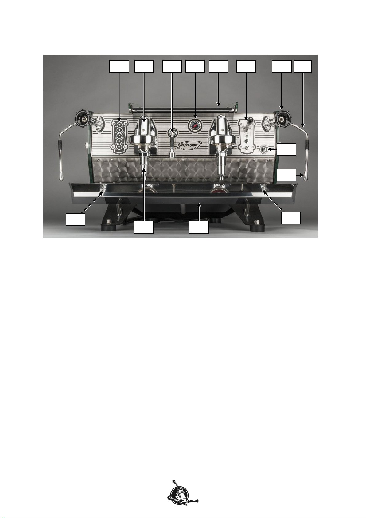
Parts identification ................................................................................................................................ 3
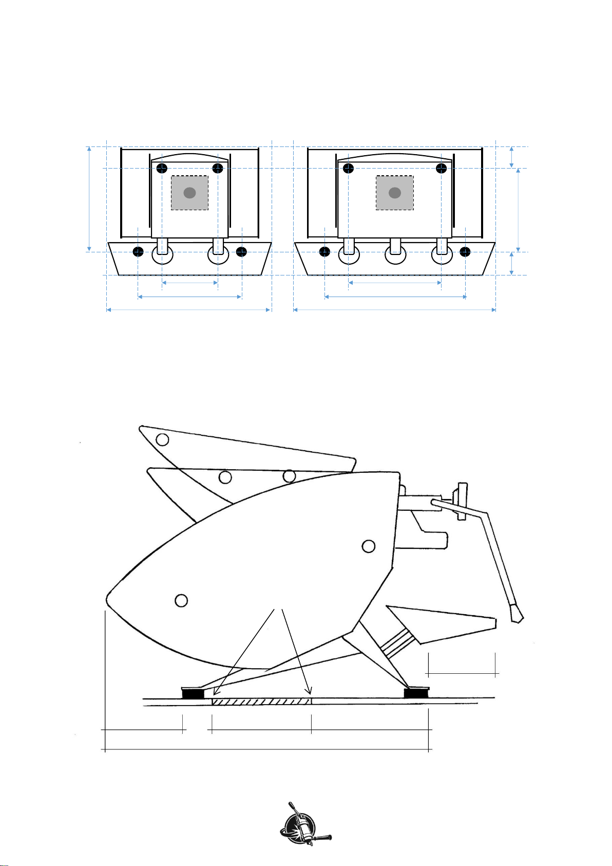
Dimensions ............................................................................................................................................ 4
Footprints............................................................................................................................................. 4
Silhouette............................................................................................................................................. 4
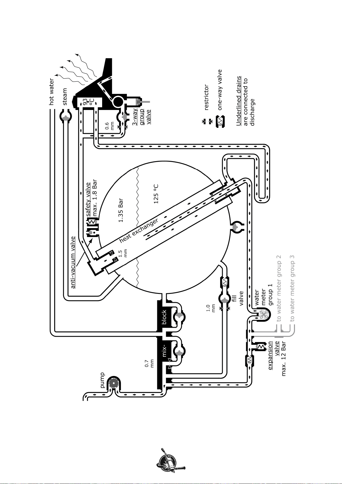
Main characteristics.............................................................................................................................. 5
Abridged machine performance .......................................................................................................... 6
Notice.................................................................................................................................................... 10
Water quality........................................................................................................................................ 11
Note on this manual ............................................................................................................................ 12
Maintenance......................................................................................................................................... 13
Handy items while performing maintenance ..................................................................................... 14
Remove body panels......................................................................................................................... 16
Boiler temperature vs steam power................................................................................................... 19
Adjust brew temperature ................................................................................................................... 21
Adjust pump pressure........................................................................................................................ 23
Check water treatment system.......................................................................................................... 24
Anti-vacuum valve............................................................................................................................. 25
Grease wands and check play between nut and ball........................................................................ 27
Check tubing from mix-block to fitting for scale build-up................................................................... 29
Check restrictor in mix-block on scale build-up................................................................................. 30
Safety valve on steam boiler ............................................................................................................. 32
Expansion valve on manifold............................................................................................................. 34
Rebuild valves ................................................................................................................................... 37
Clean probes, level and safety.......................................................................................................... 39
Replace all solenoid valves............................................................................................................... 41
Drain all water when freezing is possible.......................................................................................... 46
Technical information ......................................................................................................................... 48
Electric scheme Mirage 1-phase, Duette .......................................................................................... 48
Electric scheme Mirage 3-phase: Duette high power/Triplette.......................................................... 49
Level control and water meters ......................................................................................................... 50
Mains switch Duette .......................................................................................................................... 50
Mains switch Duette high power/Triplette.......................................................................................... 51
Triplette connector block: 3-phase or 1-phase.................................................................................. 52
Problem solving................................................................................................................................... 53
Controller........................................................................................................................................... 53
Steam boiler temperature controller.................................................................................................. 55
Solid state relay................................................................................................................................. 57
Heating element ................................................................................................................................ 61
Heating element seal......................................................................................................................... 64
More information on our website....................................................................................................... 65
Contact information ............................................................................................................................ 65

Mirage technical manual page 2 of 65
Precaution
Installation of and maintenance on the Mirage should be done by a qualified technician. Parts of the
machine can reach a temperature of close to 130 °C (266 °F). The steam/hot water boiler contains
water and pressurised steam of 125 °C at 1.4 Bar overpressure (258 °F at 20 PSI), temperature and
pressure in the coffee system reaches up to 96 °C at 12 Bar overpressure (205 °F at 175 PSI).
Danger
We cannot be held responsible for damage and/or injuries resulting from actions performed on our
machines by non-qualified personnel.
Advice for installation personnel
We do our utmost to have the machine in optimal condition before it is crated. Unfortunately storage
and/or shipment sometimes has a negative effect on the state of the machine upon arrival.
We therefore recommend to check and bench-test each machine in your workshop before installation
at a client’s location.
Body panels may become affected by prolonged exposure to salty air (transport by sea). Stains on
shiny stainless steel and polished aluminium can be removed with silver-polish and a soft cloth. Stains
on painted parts may be wiped off with wet towel, possibly with the addition of a mild detergent.
Prolonged storage may also result in deposition/crystallisation of water-dissolved minerals that can
block the small openings in the machine (restrictors at the fill valve, group valves and such) thus
affecting the performance of the machine.
Despite our careful packaging, handling of the crate may be so rough that the frame bends or parts
get damaged during transport. It is noted that the customer is responsible for additional insurance
during transport as standard compensation from the shipping company will not cover all costs.

WELCOME
Mirage technical manual page 3 of 65
Parts identification
Figure W 1. Showing main operational parts of the Mirage Duette equipped with optional pre-infusion
cylinders. Special show model with touchpad operation for the left group and bastone operation for the
right group. The Mirage Triplette is wider since it has an extra group in between the two groups shown
here but its function is identical to a Duette.
1. Mains switch, heating element indicator light(s) and fuse(s) (not visible on photo)
2. Touchpad group 1
3. Group head 1
4. Hot water spout
5. Pump pressure gauge
6. Cup-warming tray
7. Bastone unit group 2
8. Steam valve
9. Steam wand
10. Steam tip
11. Hot water switch
12. Temperature controller (not visible on photo)
13. Drip tray
14. Progressive pre-infusion cylinder (optional)
13
9
8
10
6
5
1
2
3
4
11
7
12
14

WELCOME
Mirage technical manual page 4 of 65
Dimensions
Footprints
Approximate footprints of Mirage Duette (left) and Mirage Triplette (right). Black circles are rubber feet.
Countertop feedthrough (dark grey circle; diameter 60 mm) is optimally positioned in light grey square.
Note that steam wands will protrude a few centimetres left and right from machine.
Silhouette
Side view of Mirage, measurements in millimetres.
11 cm
44 cm
11-13 cm
27 cm
50 cm
79 cm
46 cm
69 cm
98 cm
55 cm
100
220
180
75
575
all feeds through a hole in
the marked area

WELCOME
Mirage technical manual page 5 of 65
Minimum sizes of countertop openings
Pump hose
30 mm (connector diameter is 22 mm, hose is 12 mm)
Drain hose
30 mm (outer diameter is 25 mm)
Pump + drain hoses
40 mm (insert pump hoses first)
Electric cables
20 mm (mains cable plus pump cable, no plug)
All feeds through 1 opening
60 mm (insert pump hose first)
For the feed through of the water hoses and electrical cables drill a hole of 60 mm (2⅜”) diameter
in the counter; this should be no further than 15 cm (6”) (left or right) from the middle of the machine,
and between 22 and 40 cm (9” and 16”) behind the front feet (see machine side-view). The width of a
Mirage (body without steam wand) Duette is 730 mm (28.7”), the width of a Triplette is 920 mm
(36.2”). Ensure that this hole is not above the knock-box!
Where 1 or 2 optional steam foot-pedals are used: There is a hole needed for the thin rubber tube(s)
from under the machine to the foot pedal on the ground. In the counter, the 60 mm hole can be used,
but you need to bear the bottom and sides of the cabinet under the counter in mind and if there is a
plinth then this needs to have a hole of 15 mm (⅝”) diameter per hose.
Before unpacking the machine, you must be sure the area where the machine will be placed has been
prepared properly. The countertop should be level and firm enough to carry the weight of the
machine (up to 100 kg, 220 lbs), even when force is applied to it (to lock in the filter holders, tamp the
coffee bed, etc.).
The handle of the filter holder will be approximately 25 cm (10”) above the countertop. A countertop
height of 85-100 cm (33-40”) is suitable for most barista’s (170-195 cm; 5’2”–6’5”).
Main characteristics
Duette
Triplette
Dimensions
cm
inch
cm
inch
Height
52
20.5
52
20.5
Depth
67
26.4
67
26.4
Width of body
73
28.7
92
36.2
Width including steam wands
91
35.8
110
43.3
Footprint
cm
inch
cm
inch
Depth
50
19.7
50
19.7
Width, operator side
55
21.7
74
29.1
Width, rear side
32
12.6
52
20.5
Max. power consumption
kW
Amp (230 VAC)
kW
Amp (230 VAC)
Single phase
3.6
15.7
N.A.
Three-phase
5.1
22.2
6.4
27.8
Single phase, high power
5.1
22.2
6.4
27.8
Volume capacity
litre
US
litre
US
Steam boiler
12.6
3.3 gals
18.8
4.9 gals
Heat exchanger (each)
0.45
15.2 fl oz
0.45
15.2 fl oz
Weight (appr.)
kg
pounds
kg
pounds
Machine empty
65
145
80
175
Machine filled
75
165
95
210
Pump with motor
5.3
12
5.3
12
Table W 1. List of main characteristics of the Mirage.

WELCOME
Mirage technical manual page 6 of 65
Abridged machine performance
The Mirage functions according to the so-called single boiler system with heat exchanger and thermo-
siphon system. The water in the hot water/steam boiler is heated to approximately 125 °C to achieve
lasting steam power. For each group, a wide tube (the heat exchanger) runs through the hot water
boiler in which the water for brewing espresso is heated up without direct contact with the water inside
the boiler.
Within this heat exchanger the coffee brewing water is also heated up to approximately 125 °C, which
is, of course, too hot for brewing espresso. A wide and long tube running outside the boiler connects
the top of the heat exchanger to the group head and then from the group head back to the bottom of
the boiler. The group head is a modified E-61 which is made from brass, a metal with high heat
conductivity. This high heat conductivity means the group head easily takes up heat from the (warmer)
water and sheds heat to the (colder) environment, thus cooling down the water within. Since cold
water has a higher density than warm water, it will “sink” through the wide tube towards the bottom of
the heat exchanger. Warm water from the heat exchanger will replace the cooled water and a circular
flow is established. This is the so-called thermo siphon system.
At idle
At idle (no shot being pulled) the temperature in the group head is mainly affected by 3 parameters:
the flow rate of the water, the temperature of the water coming into the group head and the heat loss
to the environment (see Figure W 2). Wide conduits will lead to high flow rate and thus high
temperature of the group head, narrow conduits will lead to low flow rate and thus low temperature of
the group head. Flow rate in the wide conduits of the Mirage’s thermo-siphon system is controlled by a
flow restrictor (or jet). The restrictor is a fitting with a small opening which is either fixed or (optional)
adjustable. The conditions of the environment (the location of your Mirage) may change slightly due to
room temperature, draught and air humidity. As the temperature difference between the group head
and the environment is large (about 70 °C), a difference in room temperature hardly influences the
temperature of the group head although a high humidity or large air flow past the group head will lead
to a larger heat flow from the group head and thus lower temperature of the group head.
The flow restrictor installed in your Mirage is optimized for “normal” conditions, e.g. boiler temperature
of 125 °C, a room temperature of 18-22 °C, air humidity of 70-90% and little draught, brew water
temperature of 91-93 °C.
The first espresso
When a shot is being pulled, water is drawn from the thermo siphon system just before it enters the
group head. The water just coming from the heat exchanger is too hot but, since the flow restrictor is
located at the top of the heat exchanger and conduits are otherwise wide, flow from the lower conduit
is larger than from the upper conduit and nearly all water drawn from the system comes from within
the group head which has the right temperature. After passing through the group valve, which is
initially a little colder, the brewing water is led once more through a chamber in the group head with
large area surface such that it will adopt the group head temperature before reaching the coffee bed.
A second espresso
There is only little water contained within the group head (about 30 ml) and water from the large tubing
running from the group head down to the heat exchanger is a little bit too cold for brewing coffee. This
lower tubing contains about 30 ml as well. However, the large mass of the group head (approximately
4 kg) is capable of storing a lot of heat and since the conductivity and surface area are high, the cooler
water from the lower tubing which flows through the group head first will rapidly heat up to the right
temperature. The group valve is already heated up by the first espresso and water flows through the
group head a second time to establish the proper temperature before it reaches the coffee bed.

WELCOME
Mirage technical manual page 7 of 65
Figure W 2: Schematic hydraulics Mirage at idle. Sizes of restrictors may be different in your machine.

WELCOME
Mirage technical manual page 8 of 65
Figure W 3. Schematic hydraulics Mirage when brewing. Sizes of restrictors may be different in your
machine.

WELCOME
Mirage technical manual page 9 of 65
A large number of espresso’s
When water in the lower tube is used to brew espresso it is replaced with water from the bottom of the
heat exchanger. This water is initially too hot but is cooled considerably by cross-flow with cold water
flowing from the water supply into the heat exchanger. Cold incoming water is directed upwards in a
copper injector tubing of approximately 20 cm where it heats up along the way. Water is drawn from
the boiler through a brass fitting that completely surrounds the injector tubing such that the hot water
from the boiler is cooled by the incoming cold water. When brewing volume is high, the cross-flow
system, together with the flow restrictor at the top of the heat exchanger warrant a very stable
temperature on the coffee bed (see Figure W 3). Fluctuations in steam boiler water temperature which
result from filling have little effect on coffee water temperature as they are balanced by the large mass
of brass of the group head.
Temperature stability
The entire system allows for very stable water temperature at the coffee bed with low and high
brewing volumes in combination with high steam pressure. The water at the coffee bed can be
adjusted to as low as 88 °C by altering the flow restrictor (either by changing the fixed-opening
restrictors or by regulating the adjustable restrictors).
The temperature in the steam boiler is maintained by a very accurate electronic controller. The
measuring-tip of the temperature sensor is located above the water level in the steam boiler, not in the
boiler water itself. This is done on purpose: when a steam valve is opened, the subsequent pressure
drop in the boiler will immediately lead to a small temperature drop (adiabatic expansion) which results
in activation of the heating element. The controller allows for easy adjustment of boiler temperature.
Boiler fill
An operational level probe in the hot water/steam boiler governs automatic refilling which ensures that
water level remains constant. However, the boiler will not fill when a shot is being pulled as not to
disturb the brewing pressure.
Safety
A safety level probe just above the heating elements ensures that the Mirage heating shuts down
when water level is becoming dangerously low, with LED’s on the touchpads or bastone levers
flashing as visual warning. Overheating is furthermore prevented by a separate sensor which
interrupts power to the heating element when the temperature around the heating element exceeds
145°C (293°F).
The expansion valve in the coffee water system, which is adjusted to 11-12 Bar at our workshop, in
combination with a safety valve of 1.8 Bar on the steam boiler ensure that pressures inside the Mirage
cannot exceed safety values.
When any one of the solenoid valves within the Mirage would ever remain open for longer than 2
minutes, the complete machine will shut down. At the same time all LED’s on the touch-pads will start
blinking as a visual alarm.
User friendly
All group solenoid valves are located inside the machine and connected to the drain such that no
electric devices are in the splash zone and there is no spattering of discharging valves.
The touchpads or bastone lever units can easily be programmed individually or simultaneously to your
own shot-volume settings with the left-hand side touchpad/bastone (as seen by the barista) as
governing module. A touchpad allows for 4 different volume settings and continuous flow. A bastone
unit allows for 2 different volume settings and continuous flow.

WELCOME
Mirage technical manual page 10 of 65
The hot water flow is operated by a push-button and can be time adjusted to your needs. Hot water
from the boiler is mixed with some cold to deliver non-spattering water of the correct temperature to
prepare “Americanos”.
All parts in the Mirage which spill water or steam in whatever circumstances are connected to the
drain pipe on the back of the drip-tray. The group valves, expansion valve, pressure safety valve and
anti-vacuum valve will thus not leak any water on your counter or the Mirage’s electronics or blow
steam into your working space.
These drains have a second benefit. For example: whenever a dirt particle in the boiler fill valve
prevents it from closing, the boiler will keep filling. Such a malfunction will not be detected by the
Mirages’ computer and continues even when the machine is turned off. During opening hours you
might notice the malfunction in time. However, if it happens at the end of the day, water level in the
boiler will slowly rise until it reaches the safety valve. Since opening pressure of the safety valve is
probably lower than water mains pressure, the safety valve will be pushed open. The drain on the
safety valve prevents your workspace from being slowly flooded.
The Mirage is also equipped with an easily operated cleaning program which pressurises and de-
pressurises all groups simultaneously 8 times in a row.
The wide drain tray can be moved stepless up and down to accept any size of cup.
The elevated position of the body makes cleaning underneath the machine easy. Slightly down-
sloping handles on the filter holders ensure an ergonomically better position of the barista’s wrist.
An optional pre-infusion system can be mounted on the Mirage. This “soft-start” mechanism
(incorporating a progressive pre-infusion cylinder) absorbs pump pressure such that it increases
gradually to 3 Bar which ensures pre-wetting and swelling of the coffee grinds before extraction starts.
As an option, one or both steam valves can be switched on and off by foot for fast and efficient milk
steaming. Since the manual steam valves remain fully operable the steam flow can be adjusted to
your liking.
Notice
Filled with water, a Mirage espresso machine has a large mass and produces heat. Space in the
immediate surrounding should be available for coffee grinder, knock-box, tamper and other
accessories. The pump and water treatment (not included) should be placed in the proximity of the
machine. Water supply and discharge, as well as an AC socket with earth connection is needed. The
location of your Mirage should account for these.

WELCOME
Mirage technical manual page 11 of 65
Water quality
Since water content in an espresso is more than 90%, the quality of your water supply is highly
important for the taste of your coffee. While too much mineral content will hasten damaging lime scale
build-up inside your Mirage, an absence of minerals will give your espresso a flat taste while also
harming the boilers inside the machine. As a rule of thumb, the amount of total dissolved solids (TDS)
in your water should be 100-150 mg/l (=ppm).
We recommend that you contact your water company for details about your water quality and have a
water expert with knowledge of (local) water quality in espresso-machines help you to determine a
suitable water-treatment system. Below some guiding principles.
Hard water treated with an ion exchange water softener only has calcium replaced, and so it is wise to
further treat your water with an activated carbon or a carbon block water filter. These carbon filters
also remove other impurities that affect taste, but, on their own, are not able to remove water
hardness. Calcium and magnesium in the form of carbonates dissolved in water are the two most
common minerals that make water "hard”. It is recommended that water hardness is 2-4 German
degrees (35-70 mg/l Ca/Mg carbonate). The water treatment system hooked up to your machine
should establish these values.
The acidity (pH-value) of your water should be close to neutral (pH=7). A lower value (pH ˂6.5) will
make your espresso start to taste acidic and is corrosive to the metal parts in your machine. A higher
value (pH ˃7.5) results in bland tasting brews although it can also neutralise slightly acidic coffee
grinds. You are advised to check the acidity of your water every once in a while.
Chlorine should not be present in your water since it has a highly corrosive effect on all metal parts
(copper, brass and even stainless steel) inside your machine and makes your espresso smell and
taste awful. Chlorine treated water should therefore not be used in your machine unless chlorine is
removed from the water after the chlorine treatment (e.g. by use of an activated carbon or a carbon
block water filter).
Water Quality Parameter
Target
Acceptable range
Odor
Clean/Fresh, odor free
Color
Clear
Chlorine
0 mg/l
TDS
150 mg/l
75-250 mg/l
Calcium Hardness
51 to 68 mg/l
17 to 85 mg/l
Total Alkalinity
40 mg/l
at or near mg/l
pH
7.0
6.5 to 7.5
Sodium
10 mg/l
at or near 10 mg/l
Table W 2. Water properties for optimum taste. Source: SCAA Technical Standards Committee, 2009.
Any installed water treatment system should take the above into account and also prevent coarse
particles and aggressive components to enter the machine. We do not favour the use of de-scaling
agents in our machines and therefore recommend that the function of the water treatment system is
checked regularly. Not only changes in Alkalinity and Hardness of water, but also temperature have
dramatic effects on scale deposits and/or aggressiveness of water on the machine thus no single
water is optimal for both steam- and coffee boiler. We favour scale deposit over corrosion and advice
the use of the higher hardness value shown in the table below. Flushing the steam boiler will help to
reduce scale deposit in the steam boiler. Drawing lots of hot water reduces the scale-forming induced
by steaming due to removal of pure water.

WELCOME
Mirage technical manual page 12 of 65
°C
Alkalinity (mg/l)
↓
33
37
40
43
47
50
53
57
60
63
67
70
90
342
250
202
166
130
110
93
77
67
59
51
46
95
280
205
166
136
106
90
77
63
55
49
42
38
115
130
95
77
63
49
42
37
31
27
24
21
19
120
108
79
63
52
41
36
31
26
23
21
18
16
125
89
65
53
43
35
30
26
22
20
18
15
14
130
75
55
44
37
30
26
22
19
17
15
13
12
Table W 3. Maximum non-scaling Hardness (mg/l) by temperature and Alkalinity. With an Alkalinity of
50, ideal hardness would be about 100 mg/l for the coffee boiler (90-95 degrees) and about 30 mg/l for
the steam boiler (125 degrees). We advise to use 100 mg/l hardness at 50 mg/l Alkalinity. Source: Jim
Schulman's Insanely Long Water FAQ.
For comprehensive information about water in espresso machines we refer to: Jim Schulman's
Insanely Long Water FAQ, Originally Posted on alt.coffee.
Note on this manual
Work on the Mirage manual (touchpad version) is a continuing process. Photographs in the manual
are taken in the shop from machines being built or from parts available, they range from 2012 to 2016.
For that reason, body panels and/or parts from the machines on display may be missing and parts in
the machine you bought some time ago may not look identical to the parts shown in the manual. Over
time, sections are added and/or improved, sometimes as result of readers making comments. If you
have suggestions for improvements, do not hesitate to send them to:
support@keesvanderwesten.com.

MAINTENANCE MANUAL
Mirage technical manual page 13 of 65
Maintenance
The next section clarifies how the individual maintenance items should be carried out. Up to monthly
maintenance, the tasks are relatively easy and do not require vast technical knowledge. However,
checking and replacing parts inside the machine should be done only by an experienced and
knowledgeable espresso machine technician.
Warning!
Maintenance on the machine should be done by a qualified technician. Parts of the machine can reach
a temperature of close to 125 °C. The steam/hot water boiler contains water and pressurised steam of
125 °C at 1.35 Bar overpressure (257 °F at 19.6 PSI), temperature and pressure in the coffee system
may reach up to 96 °C at 12 Bar overpressure (205 °F at 175 PSI).
When servicing the machine it is sometimes necessary to keep the machine connected to the AC
power outlet and the machine switched “on”. In both cases there is a possibility that you touch a live
wire.
Danger
We cannot be held responsible for damage and/or injuries resulting from actions performed on our
machines by non-qualified personnel.

MAINTENANCE MANUAL
Mirage technical manual page 14 of 65
Handy items while performing maintenance
Servicing an espresso machine requires a well filled tool-cabinet, but also some special materials you
might not think of initially.
Figure M 1. Loctite 542 and 243, food-safe grease, copper-ease, Teflon O-rings, PTFE tape and
copper O-rings.
Loctite 243 is used to increase friction such that bolts, nuts and fittings will not turn loose when not
wanted. Loctite 542 helps to seal joined parts. A disadvantage is that it should not get on the
inside of the fittings/tubing as non-hardened Loctite may be transported by the water flow and clog
restrictors, solenoid valves, etc.
Food safe grease is used to reduce friction between the nuts and the tubes when tightening the
tubes to fittings, etc.
Copper Ease is an anti-seize compound with a very high temperature tolerance (up to 1150°C.
The protective coating will not wash or burn off and will help to prevent stainless steel bolts and
nuts getting stuck. Stainless steel does not corrode but is very parch, if not lubricated, a nut-bold
connection seems to “weld” together.
Teflon O-rings and/or tape is used to assure sealing of joined parts that are expected to be
loosened every once in a while. However, especially when warm, Teflon deforms easily and
should therefore not be tightened as you would a fitting sealed with a copper O-ring.
Two wooden blocks with approximate dimensions 15x5x20 cm (6x2x8 inch) to tilt the machine
backwards for easier access to the bottom of the Mirage.

MAINTENANCE MANUAL
Mirage technical manual page 15 of 65
Figure M 2. Multi meter, induction type current meter, left-hand threaded fitting extractor.
Multi-meter to check resistance, voltage, current, etc.
An induction type current (Ampere) meter may be useful to check power through the heating
elements.
Thread extractor(s) to remove broken off fittings.
Figure M 3. Temperature meter with sensor mounted in filter holder with adjustable flow and long tip
temperature sensor.
Filter holder with controlled outflow and quick response (QR) temperature sensor, separate QR-
sensor and meter to check brewing temperature and hot water temperature.

MAINTENANCE MANUAL
Mirage technical manual page 16 of 65
Remove body panels
Most parts within the machine that need regular maintenance can be accessed by removing either left
and/or right body panel and/or cup warmer.
Materials needed
Spanner 11, 13 mm
Ring spanner 8 mm
Allen key 2.5 mm, 3 mm
Copper ease
Procedure glass side panels
1. Unscrew the 2 large glass nuts on the side panel by hand (see Figure M 4a).
2. Carefully pull glass side panel away from the machine.
3. Remove the 2 brass mounting nuts (see Figure M 4b) with a 11 mm spanner.
4. Carefully pull plastic side panel away from the machine.
5. When re-mounting the side panels, check the silicone O-ring on the brass mounting nuts for
cracks, replace if necessary. Do not over tighten the brass mounting nuts.
6. Don’t forget the rubber washer between the glass side panel and the large glass nut, do not over
tighten the large glass nuts.
Figure M 4a (left). To remove glass panel loosen the glass nuts that hold the glass panel.
Figure M 4b (right). Then remove the 2 brass mounting nuts. The inset shows the silicone O-ring on
the mounting nut.
Procedure aluminium side panels (Veloce)
The aluminium side panels do not have a (black) plastic side panel mounted.
1. Unscrew the 2 nuts on the side panel with a 13 mm spanner.
2. Carefully pull aluminium side panel away from the machine, do not lose the rubber and stainless
steel washer underneath the nuts.
3. When remounting, don’t forget the rubber and stainless steel washer and do not over tighten the
nuts.
remove glass nuts
remove brass nuts

MAINTENANCE MANUAL
Mirage technical manual page 17 of 65
Procedure cup warmer
1. Lift upper cup warming tray.
2. Use a 3 mm Allen key to remove 4 bolts from lower cup warming tray (see Figure M 5).
Figure M 5. Remove lower cup warming tray: remove 4 Allen bolts, then slide towards barista side and
lift off. Note that protective film is still on parts of machine.
3. Carefully slide lower cup warming tray to barista side of machine, then lift up.
4. When re-mounting, make sure that the lower cup warming tray does not scratch the back end of
the machine. Put a little grease on the Allen bolts, do not over-tighten.
5. Replace upper cup warming tray.
do NOT remove
remove

MAINTENANCE MANUAL
Mirage technical manual page 18 of 65
Procedure upper side panels
Remove appropriate side panel first.
Warning!
It is essential to disconnect the Mirage from the power outlet before removing the upper side panels,
especially the one on the left hand side.
1. Unscrew the 2.5 mm Allen bolts on the upper finishing strip a few turns.
Figure M 6. Remove finishing strip first, then undo 2 Allen bolts at back of upper-side panel. Slide
panel forward to unhook from front panel.
2. Pull the finishing strip sideways from machine, try not to scratch the body panels.
3. Remove the two 3 mm Allen bolts from the back of the upper side panel.
4. Slide panel forward (towards barista side) to unhook from front panel.
Remounting upper side panel
1. Place upper side panel close to frame and make sure that it hooks onto front panel.
2. Mount the 3 mm Allen bolts. Make sure the barista side of the upper side panel is pushed
backwards a little and flush with the side of the front panel.
3. When remounting the finishing strip it may be useful to remove the two 2.5 mm Allen bolts on the
rear completely before remounting the strip.
4. Remount these two Allen bolts but do not tighten any of the 2.5 mm Allen bolts yet.
5. Take the glass or aluminium side panel and mount with (glass) nuts and rubber rings until it
touches both the front and rear body panels.
6. While tightening the bolts on the finishing strip, pull the Allen bolts and thus finishing strip towards
the side panel.
upper finishing
strip
2 Allen bolts

MAINTENANCE MANUAL
Mirage technical manual page 19 of 65
Boiler temperature vs steam power
The factory settings of the steam boiler temperature is 124 or 125 °C (255, 257 °F) and is maintained
by an electronic thermostat (see Figure M 7) connected to a Pt100 temperature sensor. The tip of the
sensor is located in the steam boiler above operational water level.
At idle, the temperature of the steam will be the same as that of the water and the heating element will
be switched on for a moment every once in a while to maintain the set temperature.
By placing the sensor in the steam (instead of the water), the machine reacts quickly to heat loss. As
soon as a steam valve is opened, steam pressure drops and steam temperature decreases instantly
by adiabatic expansion (while water temperature remains nearly constant). Any drop in steam
temperature is noticed by the controller which in turn activates the heating element. When cold water
flows into the boiler after the hot water tap has been used, the small decrease in temperature
immediately lowers the steam pressure and again, steam temperature drops.
Saturated steam pressure at 124 °C is about 1.25 bar (overpressure), at 125 °C it is about 1.33 bar
(see Graph M 1 and Graph M 2). This pressure is high enough for powerful and long-lasting frothing of
milk.
Figure M 7. Showing the temperature controller. The indicator dot in between the 1 and 2 of the
display is not lit which shows that the controller is not sending out a "heat-on" control signal.
Graph M 1. Saturated steam pressure versus temperature (data from www.engineeringtoolbox.com).
Note that most pressure gauges read overpressure (pressure as compared to atmospheric pressure).
90
100
110
120
130
140
0 1 2 3 4
°C
bar
1.35 Bar overpressure
water temperature 125 °C
Table of contents
Other Kees van der Westen Coffee Maker manuals

Kees van der Westen
Kees van der Westen Slim Mirage User manual

Kees van der Westen
Kees van der Westen Spirit DUETTE User manual

Kees van der Westen
Kees van der Westen Speedster Operating instructions

Kees van der Westen
Kees van der Westen Speedster User manual

Kees van der Westen
Kees van der Westen Speedster 110-120VAC User manual

Kees van der Westen
Kees van der Westen Mirage Slim Jim User manual

Kees van der Westen
Kees van der Westen Slim Jim mirage User manual

Kees van der Westen
Kees van der Westen Mirage Slim Jim User manual

Kees van der Westen
Kees van der Westen spirit User manual

Kees van der Westen
Kees van der Westen Spirit DUETTE User manual