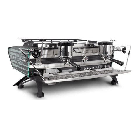
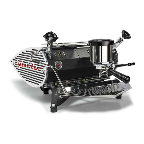
Kees van der Westen Speedster 110-120VAC User manual

CONTENTS
Speedster page 1
110-120VAC version
220-240VAC version
Installation and user manual Speedster
Document ID: Sup-Sium-Eng Date of issue: August 21, 2013 Revision date: June 28, 2017

CONTENTS
Speedster page 2
Parts identification ................................................................................................................................... 3
Unpack..................................................................................................................................................... 4
Parts included in standard shipment....................................................................................................... 4
Installation................................................................................................................................................ 5
Water quality........................................................................................................................................ 5
Connect water supply.......................................................................................................................... 7
Connect water discharge..................................................................................................................... 8
Connect to mains power and switch on............................................................................................... 9
Adjust pump pressure.......................................................................................................................... 9
Using the machine................................................................................................................................. 12
Brewing espresso.............................................................................................................................. 12
Shot timer .......................................................................................................................................... 13
Hot water ........................................................................................................................................... 14
Steam ................................................................................................................................................ 15
Change boiler temperatures.............................................................................................................. 16
Cleaning the machine............................................................................................................................ 17
Remove filter basket.......................................................................................................................... 17
Filter holder........................................................................................................................................ 17
Steam wand....................................................................................................................................... 17
Exterior .............................................................................................................................................. 18
Back flush group................................................................................................................................ 18
Replace group seal............................................................................................................................ 19
Clean group dispersion plate............................................................................................................. 20
Maintenance.......................................................................................................................................... 21
Recommended maintenance scheme............................................................................................... 21
Maintenance Records........................................................................................................................ 22
Contact information ............................................................................................................................... 23
Warning!
The Speedster is made for either 110-120VAC or 220-240VAC power supply. Make sure that the
power demands (see identity tag on front of machine) matches the local power supply before
connecting the Speedster to the mains power. We cannot be held responsible for damages resulting
from connecting the machine to incompatible mains power.

WELCOME
Speedster page 3
Parts identification
Figure W 1. Showing the main operational parts of the Speedster
1. Mains switch
2. Coffee boiler PID with temperature display
3. Hot water spout
4. 3-way brewing lever
5. 3-way hot water toggle switch
6. Coffee boiler pressure gauge
7. Hot water valve
8. Hot water valve knob (no operational function)
9. Visible end of pre-infusion piston
10. Group head
11. Shot timer display
12. Steam valve knob
13. Steam valve
14. Steam boiler pressure gauge
15. Steam tip
16. Drip tray
17. Steam boiler thermostat with temperature display
18. Filter holder
1
11
10
9
8
7
6
5
4
3
2
16
15
14
12
17
18
13
identity
tag

INSTALLATION
Speedster page 4
Unpack
Tools needed
•Phillips screw driver no. 2
Procedure
1. Remove the lid of the crate.
2. Remove the side panels.
3. Lift the machine by its legs.
Warnings!
The valves at both sides of the group are not designed to lift the machine. Lifting the machine by these
may cause the frame to bend which results in unrepairable damage.
Although sturdy, the brew lever might bend when lateral force is applied. A bent brew lever may lead
to malfunction of the lever.
Parts included in standard shipment
Accessories
•Stainless steel filter holder, 2-cup spout
•Stainless steel filter holder, 1-cup spout
•Water pump with electric motor
•Two high-pressure water supply hoses, each 1.5 m (5 ft)
•One high pressure water supply hose, 0.5 m (20 in)
•Discharge hose, inner diameter 16 mm (0.64 in)
•Stainless steel hose clamp for discharge hose
•KVDW Stainless steel tamper
•Blind filter
•Jar with cleaning powder
•Group brush
•Group screen extractor
•Drain hose
•2 KVDW shot glasses
Spare parts
•there is a Barista Kit included with the machine to facilitate routine maintenance

INSTALLATION
Speedster page 5
Installation
Caution!
Installation of and maintenance on the Speedster should be done by a qualified technician. Parts of
the machine can reach a temperature of close to 140 °C (284 °F). The steam/hot water boiler contains
water and pressurised steam of 135 °C at 1.45 bar overpressure (275 °F at 21 PSI), temperature and
pressure in the coffee system reaches up to 96 °C at 12 bar overpressure (205 °F at 175 PSI).
Danger
We cannot be held responsible for damage and/or injuries resulting from actions performed on our
machines by non-qualified personnel.
Parts needed, included in shipment
•Machine
•2 high pressure hoses, each 1.5 m (5 ft)
•1 high pressure hose, 0.5 m (20 inch)
•Pump with motor, 29x14x19 cm (length x width x height; 12x6x8 inch)
•Discharge hose with stainless steel clamp
Tools needed
•Spanner 20-22, 30 (or adjustable) mm
•Allen key 4 mm
•Screw driver
•Sharp knife and side cutter
•Bucket
Extras needed (not in shipment)
•suitable water treatment system
Water quality
Since water content in an espresso is more than 90%, the quality of your water supply is highly
important for the taste of your coffee. While too much mineral content will hasten damaging lime scale
build-up inside your Mirage, an absence of minerals will give your espresso a flat taste while also
harming the boilers inside the machine. As a rule of thumb, the amount of total dissolved solids (TDS)
in your water should be 100-150 mg/l (=ppm).
We recommend that you contact your water company for details about your water quality and have a
water expert with knowledge of (local) water quality in espresso-machines help you to determine a
suitable water-treatment system. Below some guiding principles.
Hard water treated with an ion exchange water softener only has calcium replaced, and so it is wise to
further treat your water with an activated carbon or a carbon block water filter. These carbon filters
also remove other impurities that affect taste, but, on their own, are not able to remove water
hardness. Calcium and magnesium in the form of carbonates dissolved in water are the two most
common minerals that make water "hard”. It is recommended that water hardness is 2-4 German
degrees (35-70 mg/l Ca/Mg carbonate). The water treatment system hooked up to your machine
should establish these values.
The acidity (pH-value) of your water should be close to neutral (pH=7). A lower value (pH ˂6.5) will
make your espresso start to taste acidic and is corrosive to the metal parts in your machine. A higher
value (pH ˃7.5) results in bland tasting brews although it can also neutralise slightly acidic coffee
grinds. You are advised to check the acidity of your water every once in a while.

INSTALLATION
Speedster page 6
Chlorine should not be present in your water since it has a highly corrosive effect on all metal parts
(copper, brass and even stainless steel) inside your machine and makes your espresso smell and
taste awful. Chlorine treated water should therefore not be used in your machine unless chlorine is
removed from the water after the chlorine treatment (e.g. by use of an activated carbon or a carbon
block water filter).
Water Quality Parameter
Target
Acceptable range
Odor
Clean/Fresh, odor free
Color
Clear
Chlorine
0 mg/l
TDS
150 mg/l
75-250 mg/l
Calcium Hardness
51 to 68 mg/l
17 to 85 mg/l
Total Alkalinity
40 mg/l
at or near mg/l
pH
7.0
6.5 to 7.5
Sodium
10 mg/l
at or near 10 mg/l
Table 1. Water properties for optimum taste. Source: SCAA Technical Standards Committee, 2009.
Any installed water treatment system should take the above into account and also prevent coarse
particles and aggressive components to enter the machine. We do not favour the use of de-scaling
agents in our machines and therefore recommend that the function of the water treatment system is
checked regularly. Not only changes in Alkalinity and Hardness of water, but also temperature have
dramatic effects on scale deposits and/or aggressiveness of water on the machine thus no single
water is optimal for both steam- and coffee boiler. We favour scale deposit over corrosion and advice
the use of the higher hardness value shown in the table below. Flushing the steam boiler will help to
reduce scale deposit in the steam boiler. Drawing lots of hot water reduces the scale-forming induced
by steaming due to removal of pure water.
°C
Alkalinity (mg/l)
↓
33
37
40
43
47
50
53
57
60
63
67
70
90
342
250
202
166
130
110
93
77
67
59
51
46
95
280
205
166
136
106
90
77
63
55
49
42
38
115
130
95
77
63
49
42
37
31
27
24
21
19
120
108
79
63
52
41
36
31
26
23
21
18
16
125
89
65
53
43
35
30
26
22
20
18
15
14
130
75
55
44
37
30
26
22
19
17
15
13
12
Table 2. Maximum non-scaling Hardness (mg/l) by temperature and Alkalinity. With an Alkalinity of 50,
ideal hardness would be about 100 mg/l for the coffee boiler (90-95 degrees) and about 30 mg/l for the
steam boiler (125 degrees). We advise to use 100 mg/l hardness at 50 mg/l Alkalinity. Source: Jim
Schulman's Insanely Long Water FAQ.
For comprehensive information about water in espresso machines we refer to: Jim Schulman's
Insanely Long Water FAQ, Originally Posted on alt.coffee.

INSTALLATION
Speedster page 7
Connect water supply
Figure I 1. Water treatment system (not included) on left is connected to the pump on the right. Water
flow is according to arrows. Tap and Speedster will be to left of figure.
1. Use a 20 mm spanner to attach one end of a long high pressure hose to the tap. A gasket is
not needed, the ball-shaped brass end will seal upon tightening. Inside thread on high
pressure hose is 3/8”BSPP (parallel threads, also called G 3/8”).
2. Attach the other end of the high pressure hose to the ingoing side on a suitable water
treatment system (see Figure I 1). Tighten with a 20 mm spanner. Do not use excessive force.
3. Attach the short high pressure hose to the outgoing side on the water treatment system.
Tighten with a 20 mm spanner.
4. Attach the other end of the short high pressure hose to the inlet of the pump.
Beware! The inlet of the pump is marked with an arrow pointing down, towards the pump-
housing (see Figure I 2). Tighten with 20 mm spanner.
5. Attach the second long high pressure hose to the outlet of the pump.
Beware! The outlet of the pump is marked with an arrow pointing upwards, away from the
pump-housing (see Figure I 2). Tighten with a 20 mm spanner.
Figure I 2. Pump with inlet and outlet shown.
water treatment
system
pump with
motor
inlet
outlet
inlet
outlet

INSTALLATION
Speedster page 8
6. Hold the loose end of the high pressure hose in a bucket and open the tap slowly. Flush the
water treatment system according to manufacturer's instruction. Then flush the pump for a
minute (the pump-motor does not have to run). Check if the water does not show a strange
colour or smell. Close the tap, connect the hose to the fitting at the bottom of the Speedster
with a 20 mm spanner. The Speedster may be tilted in such a way that it rests on the two
hind-legs and the back of the machine, or use (wooden) blocks under the feet see Figure I 3.
Note!
Use a permanent marker to write the expiry date on the cartridge and replace the cartridge as
advised by the manufacturer but at least every 12 months, even when the capacity is not
exceeded yet.
7. Open the tap and check the earlier made connections for leakage. Tighten when needed but
do not use excessive force. In the meantime, the front (coffee) boiler will start to fill with water.
Figure I 3. Speedster is tilted on its back, water supply and discharge hose are connected.
Connect water discharge
1. Position the stainless steel hose clamp on one end of the discharge hose. Slide the end of the
hose over the discharge-pipe of the drip tray (see Figure I 3) and tighten the hose clamp.
2. Insert the other end of the discharge hose into the sewer or a discharge container.
Beware! To prevent sedimentation of smudge, the discharge hose should slope down to your
sewer or discharge container over the entire length of the hose.
3. When necessary, cut the discharge hose to desired length.
4. Put the Speedster back on its feet.
5. Check for leaks in the connections just made.
discharge pipe
water supply
discharge hose
pump cable
power mains
supply cable

INSTALLATION
Speedster page 9
Connect to mains power and switch on
Warning! The Speedster is made for either 110-120VAC or 220-240VAC power supply. Make sure
that the power demands (see identity tag on front of machine) matches the local power
supply before connecting the Speedster to the mains power. We cannot be held responsible
for damages resulting from connecting the machine to incompatible mains power.
Beware!
A 220-240 VAC Speedster has a maximum power consumption of 3100 Watts from your AC-outlet
(max. power consumption limiter is disabled). This occurs when all three heating spirals and the pump
are active simultaneously. At 230 Volts this is equivalent to approximately 13.5 amps. We therefore
recommend that the machine has its own dedicated power circuit breaker. The max. power
consumption limiter can be made active to reduce maximum power consumption to 2300 Watts, 10
amps at 230 VAC; see leaflet that came with the Speedster.
If you have ordered a 110-120 VAC version of the Speedster (max. power consumption limiter is
active; 2050 Watts, 17.8 amps at 115VAC), you must connect your power mains to a 110-120 VAC
power outlet. The pump is fed from the Speedster and the pump-motor will be marked 110-120 VAC
as well. Where we speak of 230 VAC in the rest of this manual, you should read 110-120 VAC.
1. Make sure that the mains switch is in the "OFF"-position. The mains switch is mounted on the
identity tag on the front of the machine (see Figure W 1, item 1).
2. The thinner electrical cable attached to the Speedster is the pump cable (see Figure I 3) and
has a special type of connector. Attach the pump cable to the pump motor using the special
connectors.
3. Attach the other cable to a 230 VAC earthed power outlet. If your Speedster came without a
mains plug, it is advised to attach the blue wire to the neutral in your power outlet. (Although
there is no difference in operational aspect, this makes it easier to check the electrics in case
of a malfunction.)
4. Make sure that the Speedster rests on its feet.
5. Put the 3-way brewing lever on the right hand side of the machine (Figure W 1, item 4) in the
lowest position (Figure U 1 “pump active”).
6. Turn the mains switch on the machine to “ON”, the coffee boiler filling is continued.
7. Wait until water without air leaves the group. This procedure expels all air from the coffee
boiler. A separate bleeding procedure is not needed.
8. After this move the lever in its high “off” position. The machine will now automatically fill its
steam boiler.
The displays of both temperature regulators (see Figure W 1, items 2 & 17) will not show any value
until a minimum water level in the steam boiler is reached. Filling procedure will continue till it reaches
the maximum (operational) level.
When the temperature in the steam boiler reaches boiling point some steam will escape through the
anti-vacuum valve which makes a hissing or sputtering sound inside the machine. This will stop when
the valve is shut by the increasing pressure inside the steam boiler.
Adjust pump pressure
The right hand side pressure gauge displays the pressure in the coffee boiler. The minimum value
when the machine is at rest is the line pressure of the incoming tap water (as in other water taps in
your house). Factory setting of the maximum pressure in the boiler is 11-13 bar. Above this value an
expansion valve on the machine will open thus bleeding excessive pressure until the maximum value
is no longer exceeded (this occurs when water with a lower temperature than the set value enters the
coffee boiler, heats up and thus expands).
INSTALLATION
Speedster page 10
While brewing espresso, with the group valve “open” and the pump activated, the pressure is
supposed to increase up to 9 bar when back pressure is present (coffee puck). The pressure
generated by the pump is partly dependent on the line pressure of the building. The pump pressure
can be adjusted by turning the set screw on the right hand side of the brass pump housing (see Figure
I 4).
Notes
Do not set the pump pressure with a blind filter in the filter holder. When a blind filter is used water in
the system is trapped between a one-way valve and the blind filter. Therefore, the coffee boiler
pressure will not drop when the set screw is turned counter-clockwise.
When pump pressure exceeds approximately 12 bar, the expansion valve will open. Increasing the
pump pressure further will not result in higher coffee boiler pressure.
Do not set the operational pressure higher than 9,5 bar since this will reduce the life-span of valves,
etc. in your Speedster dramatically.
Tools needed
•Screw driver
Procedure to adjust the pump pressure:
1. Place a filter with coffee of proper grind and quantity in the filter holder.
As soon as the brew lever is activated water will flow onto the coffee bed and the gauge
indicates true extraction pressure (which is practically zero at the early stage of pre-infusion).
2. Activate the group by slotting the brewing lever in its lower (pump active) position.
3. Observe the right hand pressure gauge to check how the pressure evolves.
4. To increase the pump pressure turn the screw in the pump housing clockwise. Turn the screw
counter-clockwise to decrease the pump pressure.
Beware! The set screw is made from brass and is easily deformed. To avoid damage use a
screw driver that snugly fits the slot.
This manual suits for next models
1
Table of contents
Other Kees van der Westen Coffee Maker manuals

Kees van der Westen
Kees van der Westen Speedster 2020 User manual

Kees van der Westen
Kees van der Westen Slim Jim mirage User manual

Kees van der Westen
Kees van der Westen Mirage Slim Jim User manual

Kees van der Westen
Kees van der Westen Spirit DUETTE User manual

Kees van der Westen
Kees van der Westen Slim Mirage User manual

Kees van der Westen
Kees van der Westen Speedster User manual

Kees van der Westen
Kees van der Westen spirit User manual

Kees van der Westen
Kees van der Westen Mirage Slim Jim User manual

Kees van der Westen
Kees van der Westen Speedster Operating instructions

Kees van der Westen
Kees van der Westen Spirit DUETTE User manual