Kees van der Westen Speedster 2020 User manual

Installation and user manual
Speedster Espresso machine Model 2020
230Vac, standard (3100W; 13.5A) and Low-Amp (2200W; 9.6A) versions
(Original instructions)
Document ID: Sup-Sium-Eng Date of issue: June 10, 2020 Revision date: N.A.

CONTENT
Speedster I&U manual page 1
Designation.............................................................................................................................................. 2
Precaution................................................................................................................................................ 2
Safe operation ......................................................................................................................................... 2
Water Quality........................................................................................................................................... 3
Parts identification ................................................................................................................................... 4
Dimensions and characteristics............................................................................................................... 5
Water supply............................................................................................................................................ 6
Water treatment system .......................................................................................................................... 6
Waste/drain ............................................................................................................................................. 6
Machine location...................................................................................................................................... 6
Surface .................................................................................................................................................... 6
Pump location.......................................................................................................................................... 6
Electric mains .......................................................................................................................................... 7
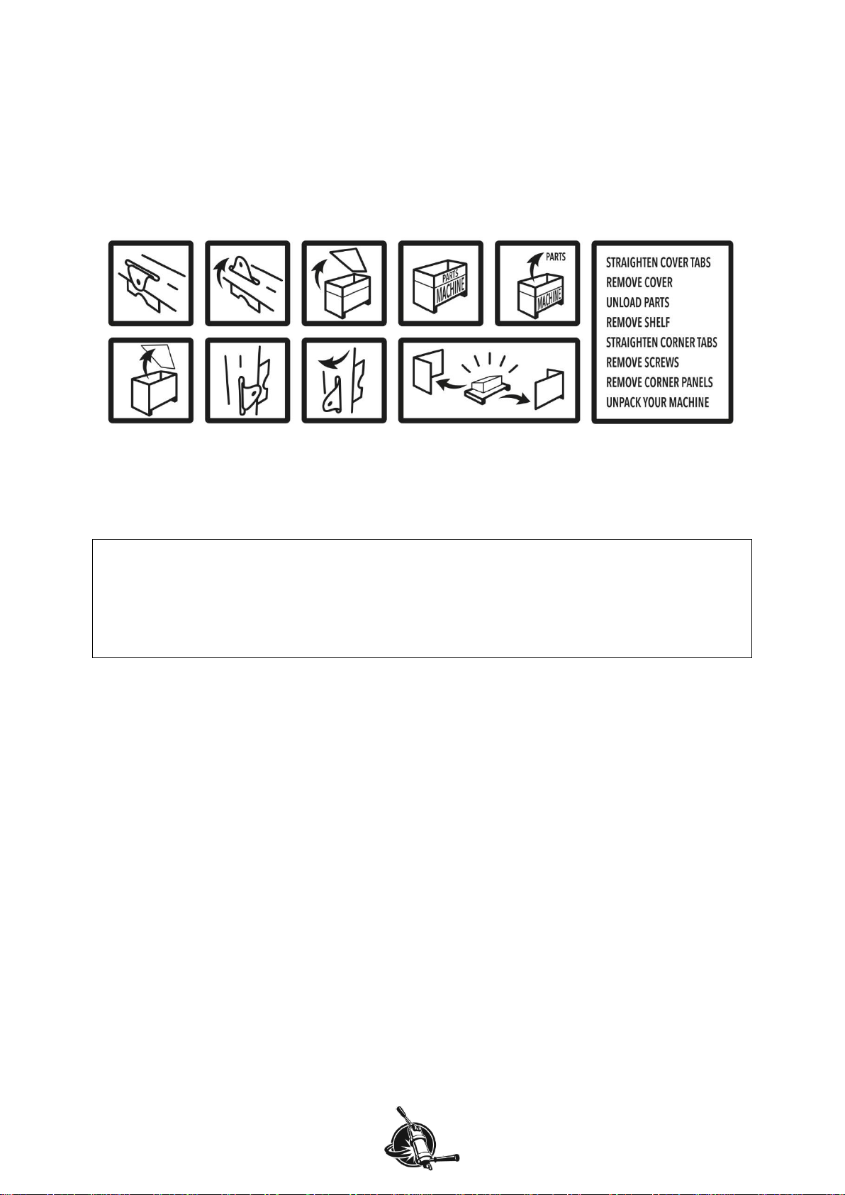
Unpack..................................................................................................................................................... 8
Parts included in standard shipment ....................................................................................................... 8
Installation................................................................................................................................................ 9
Connect water supply........................................................................................................................ 10
Connect water discharge................................................................................................................... 12
Connect to mains power and switch on............................................................................................. 13
Adjust pump pressure........................................................................................................................ 14
Using the machine................................................................................................................................. 15
Brewing espresso.............................................................................................................................. 15
Shot timer .......................................................................................................................................... 16
Pressure gauge ................................................................................................................................. 16
Hot water ........................................................................................................................................... 17
Steam ................................................................................................................................................ 19
Change boiler temperatures.............................................................................................................. 20
Cleaning the machine............................................................................................................................ 21
Remove filter basket.......................................................................................................................... 21
Filter holder........................................................................................................................................ 21
Steam wand....................................................................................................................................... 21
Clean exterior .................................................................................................................................... 22
Back flush group................................................................................................................................ 22
Replace group seal............................................................................................................................ 23
Clean group dispersion plate............................................................................................................. 24
Maintenance.......................................................................................................................................... 25
Recommended maintenance scheme............................................................................................... 25
Maintenance Records........................................................................................................................ 26
Contact information ............................................................................................................................... 27
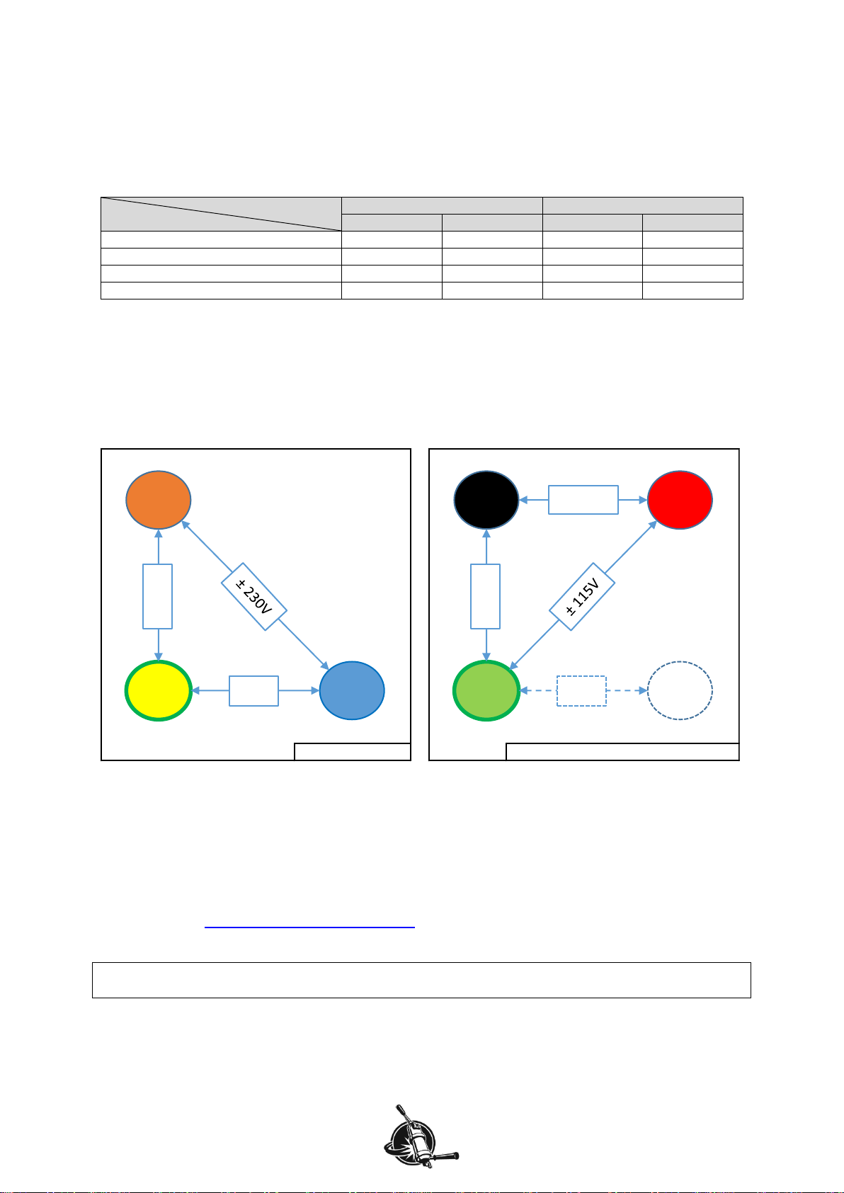
Warning!
The Speedster is made for 220-240Vac power supply (50 or 60 Hz). Make sure that the power
demands (see identity tag on front of machine) matches the local power supply before connecting the
Speedster to the mains power. We cannot be held responsible for damages resulting from connecting
the machine to incompatible mains power.
Warning!
The machine is meant to be connected to the water mains. To prevent possible water damage we
advise to install a water-spill detection system that closes the water supply in case a leak occurs.

WELCOME
Speedster I&U manual page 2
Designation
This manual applies to the Speedster espresso machine manufactured by Kees van der Westen
Espressonistic Works B.V. A separate rotational pump with electric motor is part of the appliance.
Precaution
Hot surfaces!
Parts of the machine will be hot when the machine is turned ON.
•The metal cup tray heats up by way of radiation of the boilers inside the machine and can reach
temperatures up to 75°C.
•The metal group is intended to radiate heat and can possibly reach a temperature of up to 99°C.
Hot water and/or steam!
When the machine is heated up, hot water and steam can escape from various parts of the machine
upon manipulation of a corresponding interface (valve, switch, touch-button, …).
•Activating the group will lead to water being dispensed with a temperature of up to 99°C.
•Activation of the hot water dispense can lead to steam escaping with temperatures up to 135°C as
well.
•Activating the mix-water dispense can lead to overheated water (steam) being dispensed when
the cold-water addition is not set correctly.
•Opening the steam tap will start steam escaping from the steam wand-tips, the steam can reach
temperatures up to 135°C.
Safe operation
•The espresso machine has to be placed in a horizontal position on a sturdy and flat surface.
•If the supply cord or pump cord is damaged, it must be replaced by the manufacturer, its service
agent or similarly qualified persons in order to avoid a hazard.
•The new hose-sets supplied with the appliance are to be used. Old hose-sets should not be
reused.
•Intended use of the appliance is restricted to well-trained personnel only.
•The appliance must be installed in locations where it can be overseen by trained personnel.
•The appliance may not be left unattended when there is the possibility that children and/or
vulnerable people can reach the machine.
•This appliance can be used by children aged from 8 years and above and persons with reduced
physical, sensory or mental capabilities or lack of experience and knowledge if they have been
given supervision or instruction concerning use of the appliance in a safe way and understand the
hazards involved. Children shall not play with the appliance. Cleaning and user maintenance shall
not be made by children without supervision.
•The mains electricity the appliance is connected to must include a residual-current-circuit-breaker
of 30 mA.
•The appliance may not be cleaned with the aid of a water jet.
•The appliance is not suited for outdoor use.
•Ambient temperature for correct operation of the appliance is 10-30°C (50-86°F).
•If ambient temperature falls below 5°C (41°F), keep the machine at ECO or ON to prevent freezing
of water inside the machine.
Note that the external rotational pump should be kept above freezing point of water as well.
Whenever the machine and/or pump have suffered freezing conditions, ask a technician to start-
up the appliance again.

WELCOME
Speedster I&U manual page 3
Water Quality
Have a water treatment system installed and its function checked regularly. The treatment system
should at least have a carbon block that not only traps drug-remnants, Chlorine and organic
compounds but also prevents rigid particles >30 μm to enter the pump. Optimally, the water fed into
the espresso machine would fall in the SCA “core zone”, see Figure 1, and have a pH of 7.0-7.5 (at
25°C).
Figure 1. Alkalinity vs-Total Hardness graph showing the SCA “core zone” in green outline.
Besides the Alkalinity and Total Hardness requirements, the water should have the following
properties:
Parameter
Target
Acceptable range
unit
Total Hardness
72
50-175#
ppm
Total Alkalinity
40*#
40-75#
ppm
pH
7.0*
6.5-7.5*, 6.5-8.0#
--
Electrical conductivity
< 3 times Alkalinity
(in ppm)#
μS/cm1
Total Dissolved Solids
150*
75-250*
ppm1
Calcium Hardness
51-68*
17-85*
ppm
Sodium
10*
at or near 10*
ppm
Sulphate
30
0-50
ppm
Chloride
0
0-30
ppm
Silica
0
0-5
ppm
Odour and colour
clean*, fresh*, odour free*, clear*
Taste influencing organic compounds*#
not present
Chlorine#, Hypochlorite#, Chloramines#
Iron#, Lead#, Manganese
* SCAA Technical Standards Committee, 2009: water properties for optimum taste.
# Values from “The SCAE water Chart” (2015?).
Table 1. Showing parameter values for water meant to brew coffee with.
Water with properties that lie within the SCA “core zone”and has correct pH combines technical
aspects enabling a safe operation and sensory aspects yielding a high quality brew, provided the other
parameters are met as well. High brew-ratio’s, as for espresso, shift the optimum of total hardness and
alkalinity towards higher values.
1
The conversion from electrical conductivity to TDS depends heavily on the water composition and
temperature, yielding results that can vary significantly. Additionally, even if the estimated TDS value
is accurate, it does not contain any information about what the TDS is actually made up of.
0
20
40
60
80
100
120
020 40 60 80 100 120
Total Hardness (ppm CaCO3)
Alkalinity (ppm CaCO3)
SCA
core
zone

WELCOME
Speedster I&U manual page 4
Parts identification
Figure 2. Showing the main operational parts of the Speedster.
1. Mains switch
2. Filter holder
3. Hot water spout
4. Coffee boiler PID with temperature display
5. 3-way brewing lever
6. 3-way hot water toggle switch
7. Hot water valve
8. Hot water valve knob (no operational function)
9. Visible end of dual spring pre-infusion piston (DSPIC)
10. Group head
11. Shot timer display
12. Steam valve knob
13. Steam valve
14. Coffee boiler pressure gauge
15. Steam tip
16. Drip tray
17. Steam boiler thermostat with temperature display
1
11
10
9
3
2
16
15
14
12
17
13
identity
tag
8
6
5
4
7

INSTALLATION MANUAL –check location
Speedster I&U manual page 5
Dimensions and characteristics
Figure 3. Side view (left) and top view (right) of the Speedster. Also shown the rubber feet (Ø=30 mm,
in purple) and optimal position (green circle Ø≥42mm) and near optimal location (green square
125x110mm) of counter-top feed-through.
Dimensions
Height (top of cup rail)
370 mm
Depth drip-tray to back
650 mm
Width of machine body
480 mm
Width including tap and steam wand
appr. 600 mm
Footprint
Depth (centre of feet)
338 mm
Width (centre of feet)
front
413 mm
back
121 mm
Peak power consumption at 230Vac
Watt
Amp
Standard
3100
13.5
Low-Amp
2200
9.6
Volume capacity
litre
gal / floz (US)
Steam boiler
3.5
0.9 gal
Water in steam boiler
2.0
0.5 gal
Heat exchanger
0.12
4 floz
Coffee boiler
2.1
0.6 gal
Weight
empty
filled
kg
pound
kg
pound
Espresso machine
40
88
45
100
Pump assembly
5
11
N.A.
Shipping crate
75
165
Table 2. General data for the Speedster. Shown are theoretical dimensions, actual values can deviate
+/- 5 mm.
650
470
370
338
480
650
≈600
121
338
413
≈235

INSTALLATION MANUAL –check location
Speedster I&U manual page 6
Water supply
Rated pressure: 0.1-0.5 MPa (1-5 bar)
Rated flow: minimum 4 litre/minute
The water supply should be able to deliver a minimum amount of 4 litres per minute in the range 0.1-
0.5 MPa (1-5 bar). The machine and accompanying rotary vane pump must be connected with the
supplied new set of high-pressure hoses (two hoses, each 1.5 meter long), old hose-sets should not
be re-used. The distance between water treatment system and pump and the distance between pump
and machine cannot be greater than 1.5 meter unless there is appropriate material available to
increase these distances.
Notes
Not included in the shipment are supplies to make the connection between the water-tap and the
water treatment system.
National rules/regulations may apply when the appliance is connected to the water mains.
Water treatment system
The water treatment system should also be able to deliver a minimum amount of 4 litres per minute
and should at least have a carbon block that not only traps drug-remnants, Chlorine and organic
compounds but also prevents rigid particles >30 μm to enter the pump.
If the resulting water does not fall into the SCA “core-zone” (see Figure 1) have additional treatment
installed.
Notes
Flush the water treatment system according to the manufacturers instruction before connecting it to
the pump-inlet.
Make sure that the functioning of the water treatment system will be checked on a regular basis.
Waste/drain
The appliance has a drain hose attached to the drip tray. This semi-flexible hose has an external
diameter of 20 mm (inner diameter: 15 mm). The hose must slope downwards all the way from
machine to waste to prevent clogging. The waste at the location should have a minimum inside
diameter of 20 mm to accommodate for the hose and incorporate a water-lock to prevent smelly
odours.
Machine location
The machine is only to be installed in locations where it can be overseen by trained personnel.
Areas where a water-jet could be used are not suitable as location for the machine.
Surface
The countertop must be sturdy enough to easily support the machines’ weight (when filled: up to 50kg)
plus extra equipment (one or two coffee-grinders, tableware, …). The surface should have a height of
95-100 cm and be smooth, flat and horizontal.
It is advised to think about the location of holes in the countertop where the water and waste hoses
and electric cables should pass before the machine is installed.
Pump location
There should be nearby space for the electric motor with rotary vane pump. The pump-assembly
should not be able to touch the walls of the cabinet it is located in to prevent noise. Further noise
reduction can be achieved by placing the assembly on a 2-4cm thick rubber-foam sheet with
dimensions: 16x30cm (not supplied with machine). The pump will be electrically connected to the
espresso machine with an approximately 2 m long cable with plug.
Areas where a water-jet could be used are not suitable as location for the pump-assembly.
Make sure there is air-flow possible near the motor to prevent overheating.

INSTALLATION MANUAL –check location
Speedster I&U manual page 7
Electric mains
Rated voltage: ~230V, 50/60Hz
Rated power: standard: 13.5 Amp, low peak power: 9.6 Amp (see Table 3 for details).
version
Peak power
standard
low peak power
Watt
Ampere
Watt
Ampere
Coffee boiler heating power
900
3.9
900
3.9
Steam boiler heating power
1800
7.8
1800
7.8
Max. combined heating power
2700
11.7
1800
7.8
Max. total peak power
3100
13.5
2200
9.6
Table 3. Showing peak power in the different phases for different machine versions.
Single-phase machine
The machine is meant to be connected to P-N-E (single Phase + Neutral + Earth) or 2P-E (split Phase
+ Earth) power mains, see Figure 4. Note that the 2P-E configuration does NOT make use of the
neutral wire of the electric mains. For peak power, see Table 3. The tension between the phase and
neutral (P-N-E power) or the tension between the two phases (2P-E power) should be 220-240Vac.
Figure 4. At left P-N-E, at right 2P-N-E. The machine can make use of P1 and P2 plus E (without N) of
the right electric mains configuration. Peak current is 13.5A or 9.6A, depending on version ordered.
Standard / low peak power conversion
The machine will be delivered from factory in the version ordered. The accompanying peak power
consumption will be stated on the identity tag of the machine.
Conversion to low peak power requires an extra part. This part and instruction for the conversion can
be obtained via: support@keesvanderwesten.com; include machine serial number in your email.
Note
National rules/regulations may apply when the appliance is connected to the electric mains.
~230V; P-N-E
N
L
E
±230V
±0V
2N~230V; 2P-N-E, split-phase
N
L2L1
E
±115V
±0V
±230V

INSTALLATION
Speedster I&U manual page 8
Unpack
1. Straighten the tabs that fixate the lid to the wooden crate, then remove the lid.
2. Unpack only the loose materials inside the crate.
3. Remove the shelf from the crate.
4. Straighten the tabs on the two diagonally ribs of the crate.
5. Undo the screws that hold the sides of the crate to the bottom.
6. Remove the sides of the crate from the bottom.
7. Check if all accessories are present.
8. Remove packing material from machine.
9. Check the machine for transport damage.
10. Get adequate help to lift the machine from the bottom of the crate onto the countertop.
Warnings!
Grip the machine by the legs when lifting it (onto the countertop).
The valves at both sides of the group are not designed to lift the machine. Lifting the machine by these
may cause the frame to bend which results in unrepairable damage.
Although sturdy, the brew lever might bend when lateral force is applied. A bent brew lever may lead
to malfunction of the lever.
Parts included in standard shipment
Accessories
•Stainless steel filter holder, 2-cup spout
•Stainless steel filter holder, 1-cup spout
•Water pump with electric motor
•Two high-pressure water supply hoses, each 1.5 m (5 ft)
•One high pressure water supply hose, 0.5 m (20 in)
•Discharge hose, inner diameter 15 mm (0.6 in)
•Stainless steel hose clamp for discharge hose
•KVDW Stainless steel tamper
•Blind filter
•Jar with cleaning powder
•Group brush
•Group screen extractor
•Boiler drain hose with adapter
•2 KVDW shot glasses
Spare parts
•there is a Barista Kit included with the machine to facilitate first routine maintenance

INSTALLATION
Speedster I&U manual page 9
Installation
Caution!
Installation of and maintenance on the Speedster should be done by a qualified technician. Parts of
the machine can reach a temperature of close to 135 °C (275 °F). The steam/hot water boiler contains
water and pressurised steam of 135 °C at 2.2 bar overpressure (275 °F at 33 PSI), temperature and
pressure in the coffee system reaches up to 100 °C at 12.5 bar overpressure (212 °F at 181 PSI).
Danger
We cannot be held responsible for damage and/or injuries resulting from actions performed on our
machines by non-qualified personnel.
Danger
If the supply cord or the pump connection cord is damaged it must be replaced by the manufacturer,
its service agent or similarly qualified persons in order to avoid a hazard.
The appliance is to be supplied through a residual current device (RCD) having a rated residual
operating current not exceeding 30mA.
Note
Use the new hoses supplied with the machine. Do not re-use old (high pressure) hoses.
Parts needed, included in shipment
•Machine
•2 high pressure hoses, 1.5 m (5 ft) each
•1 push-in adapter (mounted already on one high pressure hose)
•Pump with motor, 29x14x19 cm (length x width x height; 12x6x8 inch)
•Discharge hose with stainless steel clamp
Tools needed
•Spanner 20-22, 30 (or adjustable) mm
•Allen key 4 mm
•Screw driver
•Sharp knife and side cutter
•Bucket
Extras needed (not in shipment)
•suitable water treatment system
•extra hose to connect tap to treatment system

INSTALLATION
Speedster I&U manual page 10
Connect water supply
Rated pressure: 0.1-0.5 MPa (1-5 bar)
Rated flow: minimum 4 litre/minute
1. Attach a suitable water treatment system to the water tap.
2. Flush the water treatment system according to manufacturer's instruction.
3. Attach the high pressure hose without push-in fitting to the outgoing side on the water
treatment system. Tighten with a 20 mm spanner.
4. Attach the other end of the hose to the inlet of the pump.
Beware! The inlet of the pump is marked with an arrow pointing down, towards the pump-
housing (see Figure 9). Tighten with 20 mm spanner.
5. Attach the high pressure hose with push-in fitting to the outlet of the pump.
Beware! The outlet of the pump is marked with an arrow pointing upwards, away from the
pump-housing (see Figure 9). Tighten with a 20 mm spanner.
Figure 5. Speedster tilted on back for access to water supply and discharge.
6. Hold the loose end of the high pressure hose in a bucket and open the tap slowly. Flush the
pump for a minute (the pump-motor does not have to run). Check if the water from the
treatment system does not have a strange colour or smell.
7. The machine may be tilted in such a way that it rests on the two hind-legs and the back of the
machine, or use (wooden) blocks under the feet; see Figure 5. Close the tap and push the
push-in adapter to the water-inlet at the bottom of the Speedster, see Figure 7. Pull the fitting
to assure that it is correctly mounted. (It should not be possible to pull the fitting out without
simultaneously pushing the lock inwards).
Note
Use a permanent marker to write the expiry date on the cartridge and replace the cartridge as advised
by the manufacturer but at least every 12 months, even when the capacity is not exceeded yet.
8. Open the tap and check the earlier made connections for leakage. Tighten when needed but
do not use excessive force. In the meantime, the front (coffee) boiler will start to fill with water.
push-in
adapter
pump
assembly
discharge
hose

INSTALLATION
Speedster I&U manual page 11
Figure 6. Water supply, discharge hose and pump motor are connected.
Figure 7. discharge hose is clamped to discharge pipe and water supply is pushed into the machine.
Notes
Use the new hoses supplied with the machine. Do not re-use old (high pressure) hoses.
National rules/regulations may apply when the appliance is connected to the water mains.
discharge pipe
pump
assembly
pump cord
power mains
supply cable
hose clamp
pump cord
plugs

INSTALLATION
Speedster I&U manual page 12
Connect water discharge
1. Position the stainless steel hose clamp on one end of the discharge hose. Slide the end of the
hose over the discharge-pipe of the drip tray (see Figure 7) and tighten the hose clamp.
2. Insert the other end of the discharge hose into the sewer or a discharge container.
Beware!
To prevent sedimentation of smudge, the discharge hose should slope down to your sewer or
discharge container over the entire length of the hose, see Figure 8.
3. When necessary, cut the discharge hose to desired length.
4. Put the Speedster back on its feet.
5. Check for leaks in the connections just made.
Figure 8. Showing wrong and correct drain hose trajectories.
machine machine machine
waste
waste
waste

INSTALLATION
Speedster I&U manual page 13
Connect to mains power and switch on
Rated voltage: ~230Vac, 50/60Hz
Rated power: standard: 13.5 Amp, low peak power: 9.6 Amp (see Table 3 for details).
Danger
If the supply cord or the pump connection cord is damaged it must be replaced by the manufacturer,
its service agent or similarly qualified persons in order to avoid a hazard.
The appliance is to be supplied through a residual current device (RCD) having a rated residual
operating current not exceeding 30mA.
Warning!
Make sure that the power demands (see identity tag on front of machine) matches the local power
supply before connecting the Speedster to the mains power. We cannot be held responsible for
damages resulting from connecting the machine to incompatible mains power.
1. Make sure that the mains switch is in the "OFF"-position. The mains switch is mounted on the
identity tag on the front of the machine (see Figure 2, item 1).
2. The thinner electrical cable attached to the Speedster is the pump cord (see Figure 6) and
has a special type of plug. Connect the pump cord to the pump motor and secure the plug,
see Figure 7.
3. Attach the other cable to a 230 Vac earthed power outlet. If your Speedster came without a
mains plug, it is advised to attach the blue wire to the neutral in your power outlet. (Although
there is no difference in operational aspect, this makes it easier to check the electrics in case
of a malfunction.)
4. Make sure that the Speedster rests on its feet.
5. Put the 3-way brewing lever on the right hand side of the machine (Figure 2, item 4) in the
lowest position (Figure 10 “pump active”).
6. Turn the mains switch on the machine to “ON”, the coffee boiler filling is continued.
7. Wait until water without air leaves the group head. This procedure expels all air from the
coffee boiler. A separate bleeding procedure is not needed.
8. After this move the brewing lever in its high “OFF” position. The machine will now
automatically fill the steam boiler.
The displays of both temperature regulators (see Figure 2, items 2 & 17) will not show any value until
a minimum water level in the steam boiler is reached. Only when this safety level is reached, the
temperature controller displays will light up and the boilers will start to warm up. Filling procedure will
continue till it reaches the maximum (operational) level.
When the temperature in the steam boiler reaches boiling point some steam will escape through the
anti-vacuum valve which makes a hissing or sputtering sound inside the machine and may produce
some steam escaping from the drip-tray. This will stop when the anti-vacuum valve is shut by the
increasing pressure inside the steam boiler.
Note
National rules/regulations may apply when the appliance is connected to the electric mains.

INSTALLATION
Speedster I&U manual page 14
Adjust pump pressure
The pressure gauge displays the actual brew pressure (the water pressure on the coffee bed). The
minimum value when the machine is at rest is 0. Factory setting of the maximum pressure in the boiler
is 11.5-12.5 bar. Above this value the expansion valve in the coffee circuit will open, thus bleeding
pressure until the maximum value is no longer exceeded (this occurs when water with a lower
temperature than the set value enters the coffee boiler, heats up and thus expands).
While brewing espresso, with the group valve “open” and the pump activated, the pressure is
supposed to increase up to 9 bar only when back pressure is present (coffee puck or blind filter). The
pressure generated by the pump depends slightly on the line pressure of the building. The pump
pressure can be adjusted by turning the set-screw on the side of the pump housing (see Figure 9).
Note
When pump pressure exceeds approximately 12 bar, the expansion valve will open. Increasing the
pump pressure further will not result in higher brew pressure.
Tools needed
•Spanner 10mm (or large screw driver), 14 mm
Procedure to adjust the pump pressure
1. Lock a filter-holder with normally prepared coffee-bed in the group.
As soon as the brew lever is activated water will flow onto the coffee bed and the gauge
indicates true brew pressure (which is practically zero at the early stage of pre-infusion).
2. Activate the group by slotting the brewing lever in its lower (pump active) position.
3. Observe the pressure gauge to check how the pressure evolves, wait until pressure stabilises.
4. Undo the lock-nut a few turns. To increase the pump pressure turn the set-screw in the pump
housing clockwise. Turn it counter-clockwise to decrease the pump pressure.
Beware!
To prevent ruining the threads, the plastic lock nut on the set-screw should not be tightened with much
torque.
Figure 9. Showing the set screw on the pump to change pump pressure.
Note
Do not fine-adjust the pump pressure with a blind filter in the filter holder. When a blind filter is used
water in the system is trapped between a one-way valve and the blind filter. Therefore, pressure in the
coffee system will not drop when pump pressure is reduced.
set
screw
lock
nut
increase
pressure
decrease
pressure

USER MANUAL
Speedster I&U manual page 15
Using the machine
Brewing espresso
The 3-way brewing lever on the right hand side of the machine (see Figure 10) operates the group
valve and the pump. The lever can be fixed in 2 slots and thus has three operating positions:
1. OFF. Lever in upper (resting) position. Group is inactive (valve is closed and pump is off).
Water cannot flow from the coffee boiler to the coffee bed.
2. PRE-INFUSION. Lever in middle position. Group valve is open but pump is off. In this position
(hot) water under line pressure can reach the coffee grinds and flow into the pre-infusion
cylinder upon which the grinds will wet and swell. This process is called manual pre-infusion.
You may adjust the timespan of pre-infusion to your liking.
3. PUMP ACTIVE. Lever in lower position. Group valve is open and pump is activated. The water
pressure on the coffee bed will increase to 9 bar (or other pump-setting).
Switching off is easily accomplished by a short down-right tap on the left hand side on the lever. The
lever will return to its resting position and the remaining pressure in the coffee filter will be discharged.
Figure 10. Brew lever with lever positions, progressive pre-infusion cylinder and hot water toggle
switch.
When you switch from resting position directly to the lower-left position, the primary increasing
pressure is still absorbed by a piston and spring within the so-called “pre-infusion cylinder” up to
approximately 3.5 bar. Only when the piston reaches its ultimate position, the full pump pressure of 9
bar is applied to the coffee bed. You can easily check the functioning of the pre-infusion as the guiding
rod of the piston will protrude through an opening in the front panel of the machine just left of the hot
water tap (see Figure 10).
The extraction can be further manipulated by switching the lever from lower to middle position near the
end of the extraction phase. Water pressure will then decrease to line pressure (approximately 3 bar)
but remains at that level until the brew is stopped (lever in upper position).
The pre-infusion cylinder has the extra advantage that clean water in the cylinder is pushed through
the group valve into the discharge after each extraction, thus rinsing the valve.
Note
Filling of the steam/hot water boiler is disengaged during brewing (brewing lever in middle or lower
position) in order to prevent brew pressure differences during extraction.
pre-infusion
pump active
OFF
brew lever
dual spring pre-
infusion cylinder
hot water
toggle switch

USER MANUAL
Speedster I&U manual page 16
Shot timer
When the group valve is active (open) for longer than 0.1 second, a timer first re-sets to zero and then
starts to count. The display (see Figure 11) will show the seconds passed since the valve was opened.
It does not distinct between pump active or inactive. The shot timer may help you to determine the
optimum coffee-bed preparation to reach a perfect espresso (25-35 seconds).
Figure 11. The shot timer display and (brew) pressure gauge.
Pressure gauge
The pressure gauge (see Figure 11) shows the water pressure in the tube running from group valve to
coffee-bed. This means that when the group is inactive (open connection between coffee-bed and
drain) the pressure gauge will display 0 bar. When brewing a shot the coffee-bed becomes less
permeable after wetting (pre-infusion stage) and pressure will rise until line- or pump pressure is
reached (ideally 9 bar).
If 9 bar pressure is not reached during a normal brew, either the pump pressure is set too low, or the
coffee-bed was not able to produce enough counter pressure (not enough coffee grinds, coffee grinds
too coarse, channelling in coffee-bed during extraction, …), or the gauge is malfunctioning.
If the pressure gauge does not display 0 bar when the group is inactive, it is likely that the gauge is
malfunctioning: call in a technician.
Checking opening pressure of expansion valve
You can check the opening pressure of the expansion valve of a group by first having a long flush
(about 20 seconds) then quickly locking in a blind filter and activating the group again. After filling of
the pre-infusion cylinder pressure will quickly rise to pump pressure and then the expansion of heating
up the inflow of cold water will slowly increase the pressure inside the coffee system above pump-
pressure. The gauge should reach a maximum value between 11 bar and 13 bar and then remain
near constant. If the pressure rises above 13 bar, the expansion valve should be replaced. If the
pressure does not rise above pump-pressure, the expansion valve may need replacement or the one-
way valve in the coffee-circuit may be malfunctioning: call in a technician.
shot timer
display
brew pressure
gauge

USER MANUAL
Speedster I&U manual page 17
Hot water
A three-way toggle switch, located on the right hand side between the brew lever and the hot water
valve, controls the hot-water distribution (see Figure 10 and Figure 12). The valve knob itself is purely
visual and has no operational function.
Figure 12. Hot water: toggle switch, valve knob and hot water spout.
When the switch is pushed downwards the machine will automatically mix a small amount of cold
water with hot water from the steam boiler. The main advantage is that the result is a steady, non-
sputtering, flow of hot water. The addition of cold water has as extra advantage that less water from
the steam boiler is used for the same amount of liquid thus diminishing the load on the steam boiler
heating element.
When the switch is pulled upwards no cold water is mixed with hot water from the steam boiler. In this
position near-boiling water with some steam leaves the spout.
The steam boiler will re-fill automatically, also activating the pump. A flow restrictor with an opening of
0.6 mm diameter regulates the inflow such that the heating element can warm the incoming water as
efficiently as possible.
Although the boiler will not fill when a shot is pulled as not to disturb the process of espresso
extraction by a fluctuating water pressure it is possible to draw (mix-) water from the tap while brewing.
When drawing mix-water while brewing, brew pressure will decrease a little as water can also flow to
the hot water spout. It is up to the barista to make the decision if such small pressure drop is
acceptable or that hot water dispensing should wait for the brew to finish.
Adjust mix-water temperature
The temperature of the mix-water depends on steam boiler temperature and thus steam pressure and
the amount and temperature of cold water added. The amount of cold water added depends on pump
pressure and the cold-water orifice size. With a set-screw the orifice size can be adjusted to obtain the
wanted mix-water temperature. Factory setting of the mix-water temperature is 90-95°C and is based
on 135°C steam boiler temperature (2.2 bar steam pressure), 9 bar pump-pressure and appr. 15°C tap
water temperature. The set-screw can be reached and adjusted via an opening in the lower body
panel, see Figure 13. Counter-clockwise adjustment will decrease the temperature, clockwise will
increase the temperature of the mix-water.
off
hot (85-95°C)
very hot (>100°C)
toggle switch
spout
valve knob;
no function

USER MANUAL
Speedster I&U manual page 18
Figure 13. Showing how to adjust the mix-water temperature.
tools needed
•small screw driver with short handle
•(very) quick response thermometer
procedure
1. Have the machine at operation for at least 30 minutes with the steam valve used for at least
30 seconds continuously.
2. Dispense approximately 150 ml mix-water (to heat up pipes etc.) and discard.
3. Dispense approximately 150 ml in a plastic cup (to heat up cup) set aside.
4. Wait for the steam boiler to be topped-up again and heated up (the indicator dot on the
temperature display goes OFF.
5. Discard water from heated cup and immediately dispense approximately 150 ml new mix-
water in the pre-heated cup.
6. Measure the water temperature.
7. If water temperature is too low, turn set screw counter-clockwise (and vice versa).
8. Repeat the temperature check after adjustment.
If you do not have a quick-response thermometer, turn the set screw clockwise until the dispensed
water just starts to sputter (indicating boiling water), then screw counter-clockwise for ¼ turn.

USER MANUAL
Speedster I&U manual page 19
Steam
The left valve is the steam valve (see Figure 14). Turning the steam valve knob counter-clockwise will
open the valve. Before steaming milk it is necessary to open the valve for a short while to purge the
water from the steam wand. This water is condensate from steam coming in contact with the cold
tubing, valve and wand. Position the tip of the steam wand over the drip tray when purging the
condensation.
Foot operated steam valve
The 2020 version of the Speedster can optionally be equipped with a foot operated steam valve. A
floor pedal activates a momentary air-switch in the machine that in turn activates a solenoid valve. The
solenoid valve will be either closed or fully open, steam power can then be adjusted by turning the
valve knob.
Warning!
The steam valve is a spring loaded valve with the spring actually keeping the valve closed. Use no
force to close the steam valve since this will wear down the Viton and silicone parts within the valve.
Turn clockwise just until no more steam is leaving the tip, at that point the valve is closed. Total travel
of the knob from close to fully open is about ¼ turn, opening further does not have any effect.
Figure 14. Turn steam valve anti-clockwise to open.
brew pressure
gauge
steam tip
This manual suits for next models
2
Table of contents
Other Kees van der Westen Coffee Maker manuals

Kees van der Westen
Kees van der Westen Speedster 110-120VAC User manual

Kees van der Westen
Kees van der Westen Spirit DUETTE User manual

Kees van der Westen
Kees van der Westen Speedster Operating instructions

Kees van der Westen
Kees van der Westen spirit User manual

Kees van der Westen
Kees van der Westen Mirage Slim Jim User manual

Kees van der Westen
Kees van der Westen Speedster User manual

Kees van der Westen
Kees van der Westen Slim Mirage User manual

Kees van der Westen
Kees van der Westen Mirage Slim Jim User manual

Kees van der Westen
Kees van der Westen Slim Jim mirage User manual

Kees van der Westen
Kees van der Westen Spirit DUETTE User manual