Kees van der Westen Slim Mirage User manual

Slim Jim User manual page 0
User manual Slim Jim Idrocompresso
espresso machines
(Original instructions)
Document ID: Sup-JIum-Eng Date of issue: May 31, 2022 Revision date:

CONTENT
Slim Jim Idrocompresso User manual page 1
Designation............................................................................................................................................ 2
Precaution.............................................................................................................................................. 2
Safe operation........................................................................................................................................ 2
Water Quality ......................................................................................................................................... 3
Water mains pressure........................................................................................................................... 4
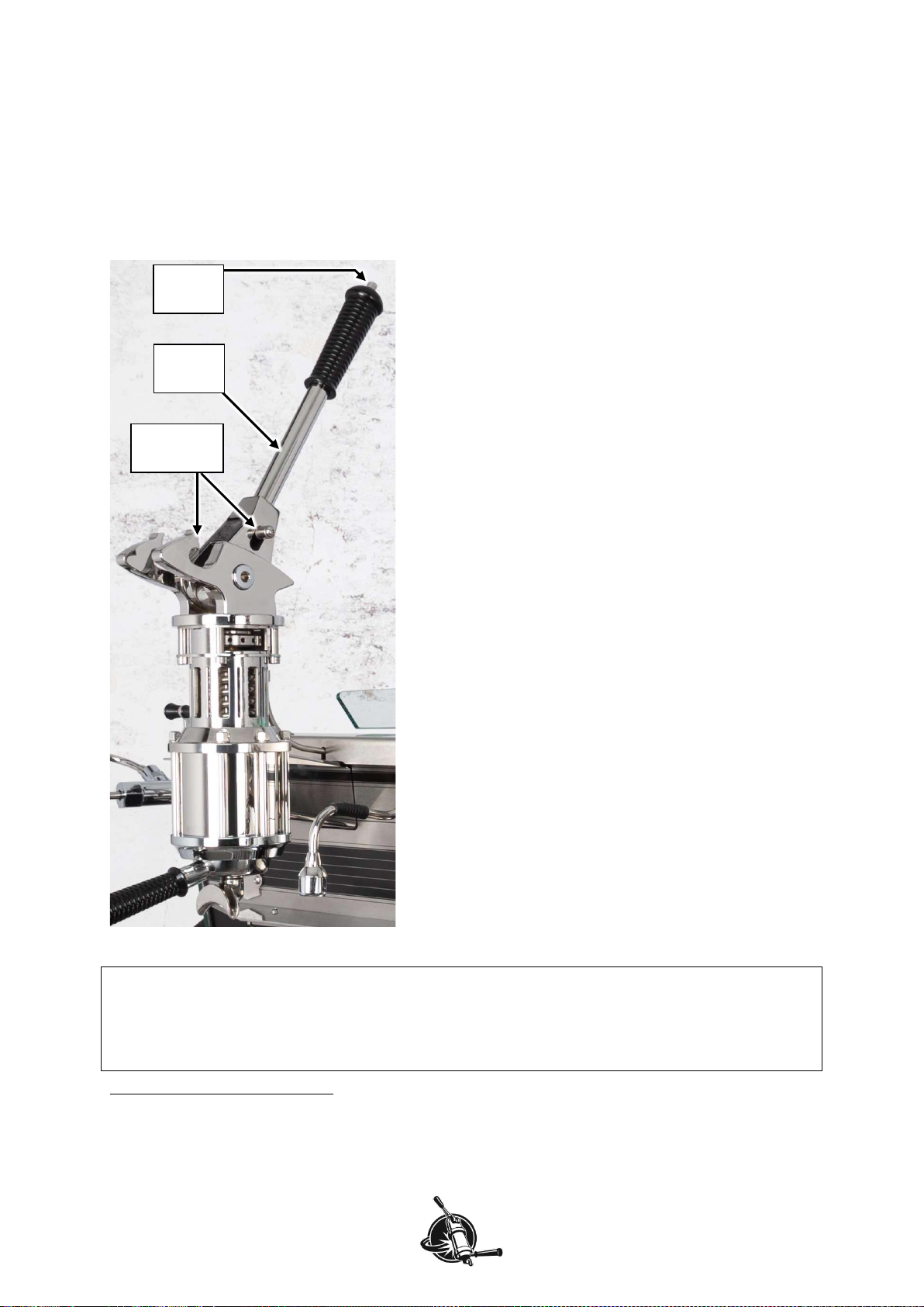
Parts identification ................................................................................................................................ 5
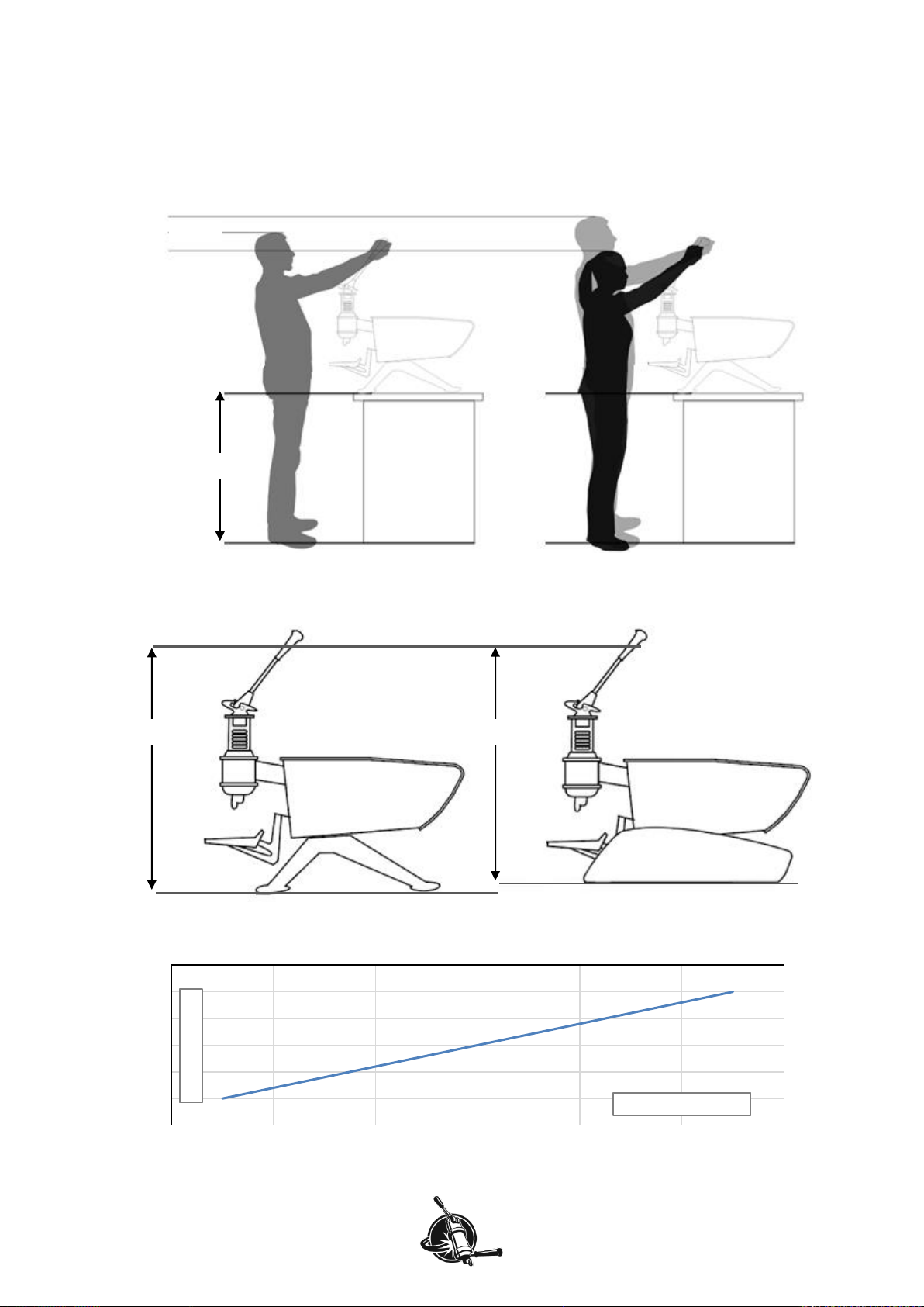
Bar height............................................................................................................................................... 6
Operational features.............................................................................................................................. 7
MAIN switch......................................................................................................................................... 7
HEAT switches .................................................................................................................................... 7
Circuit breakers ................................................................................................................................... 7
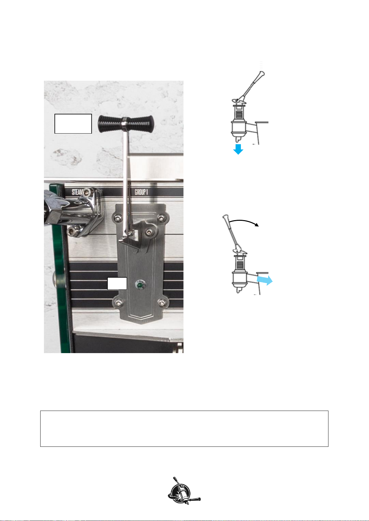
Brew-lever mechanism........................................................................................................................ 8
Flush/relief unit .................................................................................................................................... 9
Adjust resting spring length to match groups.................................................................................... 10
Temperature display.......................................................................................................................... 12
Shot time............................................................................................................................................ 12
Pressure gauge ................................................................................................................................. 13
Dispensing hot water......................................................................................................................... 13
Steaming............................................................................................................................................ 14
Control panel ....................................................................................................................................... 15
Change individual boiler to ECO and back........................................................................................ 15
Go to stand-by................................................................................................................................... 16
Sensor malfunction............................................................................................................................ 17
Start automatic back-flush program .................................................................................................. 17
Technical assistance......................................................................................................................... 18
Use (optional) external temperature sensor...................................................................................... 19
Change settings in the Barista menu................................................................................................ 20
Sub-menu TEMP. SETTING ............................................................................................................. 20
Sub-menu WATER TIMER................................................................................................................ 21
Sub-menus TIMED ON/OFF and TIME/DATE.................................................................................. 21
Why switch to ECO … ....................................................................................................................... 22
… and not to OFF?............................................................................................................................ 22
Water supply pressure-reducer setting ............................................................................................ 23
Adjust................................................................................................................................................. 23
Check................................................................................................................................................. 23
Machine cool-down ............................................................................................................................. 24
Daily to weekly maintenance.............................................................................................................. 25
Use hot water from the machine ....................................................................................................... 25
Clean body ........................................................................................................................................ 25
Daily cleaning .................................................................................................................................... 25
Lubricate and replace piston rings .................................................................................................... 29
Clean group dispersion set................................................................................................................ 31
Replace dispersion base and plate ................................................................................................... 32
Descaling........................................................................................................................................... 32
Check machine condition, report malfunctions............................................................................... 33
Free-flowrate ..................................................................................................................................... 33
Heating element indicator lights ........................................................................................................ 33
Check pressure gauges..................................................................................................................... 34
Opening pressure of expansion valve............................................................................................... 34
Consistency in programmed volumes ............................................................................................... 34
External temperature probe (option) ................................................................................................. 35
Recommended maintenance and service scheme .......................................................................... 36
Service Record .................................................................................................................................... 37
Contact information ............................................................................................................................ 39

Introduction
Slim Jim Idrocompresso User manual page 2
Designation
This manual applies to the Slim Jim 2-group (Duette) and 3-group (Triplette) espresso machines with
Idrocompresso operation manufactured by Kees van der Westen Espressonistic Works B.V. A
separate rotational pump with electric motor and adjustable pressure reducer can be part of the
appliance.
Precaution
Hot surfaces!
Parts of the machine will be hot when the machine is turned ON.
•The cup tray is equipped with an active heating element and can reach temperatures up to 75°C.
•The metal groups are intended to radiate heat and can reach a set-temperature of up to 99°C.
Hot water and/or steam!
When the machine is heated up, hot water and steam can escape from various parts of the machine
upon manipulation of a corresponding interface (valve, switch, touch-button, …).
•Activating the group will lead to water being dispensed with a temperature of up to 99°C.
•Activation of the hot water dispense can lead to steam escaping with temperatures up to 130°C as
well.
•Activating the mix-water dispense can lead to overheated water (steam) being dispensed when
the cold-water addition is not set correctly.
•Opening the steam tap will start steam escaping from the steam wand-tips, the steam can reach
temperatures up to 130°C.
Safe operation
•It is possible that the brew-lever returns to resting position with high velocity, force and
momentum. Keep body-parts other than your hand away from the reach of the brew-lever.
•The espresso machine has to be placed in a horizontal position on a sturdy and flat surface.
•If the supply cord is damaged, it must be replaced by the manufacturer, its service agent or
similarly qualified persons in order to avoid a hazard.
•The new hose-sets supplied with the appliance are to be used. Old hose-sets should not be
reused.
•Intended use of the appliance is restricted to well-trained personnel only.
•The appliance must be installed in locations where it can be overseen by trained personnel.
•The appliance may not be left unattended when there is the possibility that children and/or
vulnerable people can reach the machine.
•This appliance can be used by children aged from 8 years and above and persons with reduced
physical, sensory or mental capabilities or lack of experience and knowledge if they have been
given supervision or instruction concerning use of the appliance in a safe way and understand the
hazards involved. Children shall not play with the appliance. Cleaning and user maintenance shall
not be made by children without supervision.
•The mains electricity the appliance is connected to must include a residual-current-circuit-breaker
of 30 mA.
•The appliance may not be cleaned with the aid of a water jet.
•The appliance is not suited for outdoor use.
•Ambient temperature for correct operation of the appliance is 10-30°C (50-86°F).
•If ambient temperature falls below 5°C (41°F), keep the machine at ECO or ON to prevent freezing
of water inside the machine.
Whenever the machine has been at freezing conditions, ask a technician to start-up the appliance
again.
•It is advised to install a leak prevention system as the appliances is directly connected to the water
mains. An unattended leak can cause serious damage to the premises.

Introduction
Slim Jim Idrocompresso User manual page 3
Water Quality
Have a water treatment system installed and its function checked regularly. The treatment system
should at least have a carbon block that not only traps drug-remnants, Chlorine and organic
compounds but also prevents rigid particles >30 μm to enter the pump.
Optimally, the water fed into the espresso machine would fall in the higher part of the SCA “core
zone”, see Figure 1, and have a pH of 7.0-7.5 (at 25°C).
Figure 1. Alkalinity vs-Total Hardness graph showing the SCA “core zone” in green outline.
Besides the Alkalinity and Total Hardness requirements, the water should have the following
properties:
Parameter
Target
Acceptable range
unit
Total Hardness
72
50-175#
ppm
Total Alkalinity
40*#
40-75#
ppm
pH
7.0*
6.5-7.5*, 6.5-8.0#
--
Electrical conductivity
< 3 times Alkalinity
(in ppm)#
μS/cm1
Total Dissolved Solids
150*
75-250*
ppm1
Calcium Hardness
51-68*
17-85*
ppm
Sodium
10*
at or near 10*
ppm
Sulphate
30
0-50
ppm
Chloride
0
0-30
ppm
Silica
0
0-5
ppm
Odour and colour
clean*, fresh*, odour free*, clear*
Taste influencing organic compounds*#
not present
Chlorine#, Hypochlorite#, Chloramines#
Iron#, Lead#, Manganese
* SCAA Technical Standards Committee, 2009: water properties for optimum taste.
# Values from “The SCAE water Chart”(2015?).
Table 1. Showing parameter values for water meant to brew coffee with.
Water with properties that lie within the SCA “core zone”and has correct pH combines technical
aspects enabling a safe operation and sensory aspects yielding a high quality brew, provided the other
parameters are met as well. High brew-ratio’s, as for espresso, shift the optimum of total hardness and
alkalinity towards higher values within the core zone.
1
The conversion from electrical conductivity to TDS depends heavily on the water composition and temperature, yielding results
that can vary significantly. Additionally, even if the estimated TDS value is accurate, it does not contain any information about
what the TDS is actually made up of.
0
20
40
60
80
100
120
020 40 60 80 100 120
Total Hardness (ppm CaCO3)
Alkalinity (ppm CaCO3)
SCA
core
zone

Introduction
Slim Jim Idrocompresso User manual page 4
Water mains pressure
For best performance, the Idrocompresso requires that water supply pressure at the machine is
constant at a setting within the range 3.0 - 4.0 bar. Since some pressure is lost within a water
treatment system, water mains pressure should be a little higher than 3-4 bar. The optimum water
pressure will depend on the characteristics of the prepared coffee-bed and should be established
experimentally (see page 23).
The machine comes with a pressure reducer that will decrease higher pressure to the set value. It will
even out pressure fluctuations, provided that mains pressure is always high enough (constantly above
the set pressure). See Figure 2: when your water line pressure is high enough to produce over 4 bar
downstream of the water treatment system, you will not need a pump to increase water pressure. If
water pressure ever drops to below 3 bar, we advice that you install a pump. If water pressure at any
time of operation is known to fall below 2 bar, the optional pump (or other pressure increasing device)
is a must.
water
mains
> 4 bar
water
treatment
one-way
valve
pressure
reducer
3-4 bar
Slim Jim
Idro-
compresso
water
mains
< 2 bar
water
treatment
one-way
valve
required
pump
5-6 bar
pressure
reducer
3-4 bar
Slim Jim
Idro-
compresso
Figure 2. Depending on water mains pressure you may need a pump or not. With water mains
pressure in the range 2-4 bar the users should experimentally decide if the pressure at the machine is
high enough for proper pre-infusion.

WELCOME
Slim Jim Idrocompresso User manual page 5
Parts identification
Figure 3. Showing the main operational parts of the Slim Jim Duette Idrocompresso version with fat-
tube legs. The Slim Jim Triplette has three groups but its functions are identical to the Duette.
1. Right hand group 3-digit display (shot-timer and/or temperature)
2. Main switch (switches power to everything but the heating circuits)
3. Heat switches 1, 2 and 3 (switches power to steam boiler and group heating)
4. (Centre group 3-digit display; only on Triplette: shot-timer and/or temperature)
5. Capacitive interface and display of controller
6. Left hand group 3-digit display (shot-timer and/or temperature)
7. Flush and relief handle
8. Group
9. Group lever
10. Hot water spout
11. Hot water button switch (mix-water)
12. Hot water toggle switch (hot water only)
13. Coffee brew pressure gauge (right group)
14. Steam valve (right)
15. Steam wand (right)
A. Cup-rack (glass-look version)
B. Drip-tray
Not visible on this photo:
•Green indicator lights for heating spirals (one for each spiral; see page 33)
•Connection for external temperature probe (see page 35).
8
10
B
A
7
15
14
13
11
12
1
2
3
(4)
5
6
9

Introduction
Slim Jim Idrocompresso User manual page 6
Bar height
It requires force to pull the lever. For easiest operation it is advised to have the centre of the handle at
approximately the same height of the operators’ eyes. Ideal bar height thus depends on average
length of the operators and type of machine legs.
Figure 4. Ideal machine height (left) will be a compromise with baristas of different length (right). When
the operator is 175 cm tall, the ideal bar height will be 85 cm for machines with other than caterpillar
legs. With caterpillar legs, add 7 cm bar-height.
Figure 5. Height of centre of handle above bar. With caterpillar legs (right) the height above bar is
appr. 77 cm. For all other type of legs (left) the height is 82 cm.
Figure 6. “Ideal” bar height as function of barista length. With caterpillar legs, increase bar height with
4-5 cm.
55
65
75
85
95
105
115
145 155 165 175 185 195 205
bar height (cm)
barista length (cm)
82 cm
77 cm
175 cm
85 cm

Slim Jim Idrocompresso User manual page 7
Operational features
MAIN switch
Notes!
The machine will re-start over and over again when the capacitive screen is touched during start-up.
Dirt and remnants of detergent may unexpectedly activate the capacitive screen. If the machine does
not start up properly, clean the surface of the capacitive screen with plain water and a soft cloth.
The main switch (see Figure 7) is located at the right hand side of the machine and has 2 positions:
DOWN=OFF Power to the controller is disconnected. When the machine is functioning correctly, all
heating is also off, whatever the position of the heat switches. With a malfunction it is
however possible that one (or more) heating elements/sections are still active.
UP=ON The machine is connected to the electric mains, but power to the heating elements will
remain disconnected as long as the heat switches are still off. The machine functions
but the boilers will not heat. The optional cup-heater may function if it is turned on.
Figure 7. Showing the three HEAT switches, the MAIN switch and a blank TEMP/TIMER (3-digit)
display.
HEAT switches
Heating power to the machine is split in three different circuits. Each circuit can be (dis-)connected
individually. The heating element of the steam boiler consists of a lower, middle and upper section.
Notes!
The boilers will not heat up when the HEAT switches are in the OFF position.
With the main switch in OFF position, the boilers should not heat up, irrespective of the position of the
HEAT switches. With a malfunction, heating may be ON even with the main switch in OFF position.
1. HEAT 1 powers the left group heating element and the lower section of the steam boiler heating
element.
2. HEAT 2 powers the central (Triplette) or right (Duette) group heating element and the middle
section of the steam boiler heating element.
3. HEAT 3 powers the right group heating element (Triplette only) and the upper section of the steam
boiler heating element.
Circuit breakers
The machine has an individual breaker for each of the four electrical circuits in the machine (main-
circuit plus 3 heat-circuits). When one of the circuits has a malfunction (electric short), the
corresponding breaker will cut power to that circuit only. If the main-circuit breaker is activated the
machine will be completely inoperable but if a single heat-circuit breaker is activated the rest of the
machine will remain functional.
The circuit breakers are located within the electrics tray and cannot be accessed by the barista. If a
circuit breaker is activated, have a technician check and repair the machine as soon as possible.

Operation
Slim Jim Idrocompresso User manual page 8
Brew-lever mechanism
Pulling the brew-lever towards you activates valves, lifts a piston and shortens a spring. The brew-
lever will lock into position when maximum upward-travel of the piston is reached. When the brew-
lever is very close to the locking position, a valve is opened such that water can flow into the cylinder
and pre-infusion starts under incoming water pressure. When the machine is equipped with the
optional pump, the pump will activate at that moment as well. Active-duration of the pump can be
adjusted per individual group in the “water timer” section of the Barista level under “PUMP-ON-TIME”.
In a lever-group, spring force on a piston is used to obtain
elevated water pressure onto the coffee bed. At resting
position the spring is already shortened, pulling the brew-
lever towards you shortens the spring even more. With
the brew-lever returning to resting position, water
pressure onto the coffee-bed thus decreases during the
brew as the piston moves down and the stressed spring
relaxes. Typical lever mechanism brew-pressure profile
from start to end of a brew is approximately 9 to 6 bar.
You would normally perform a short flush (see next), lock
in the prepared portafilter, confidently2pull the brew-lever
into locked position, wait until you see the first drop of
coffee in the cup and then release the brew-lever to
extract at elevated pressure.
Pressing the release pin on top of the grip will release the
lock, the stressed spring then forces the piston down
which pressurises the water flowing through the coffee-
bed. Very shortly after the brew lever has left lock-position
a valve in the machine closes such that no more water
can flow from the machine towards the cylinder or vice
versa.
Total down-travel of the piston will result in approximately
60 ml of water being pushed through the coffee-bed,
enough for two single espressos.
When the lever returns to resting position, the electric
circuit is opened, the relief valve will de-activate.
The Bowden cable on the back of the brew-lever
mechanism operates two switches inside the machine.
The first switch will start/stop the shot-timer and close the
relief valve, the second switch will allow water to flow from
the machine to the cylinder and instructs the optional
pump to start.
Figure 8. The brew-lever mechanism.
Danger
Despite the measures taken to reduce the danger, under certain circumstances (obstructed water
flow, no coffee-bed, portafilter not properly locked in) it is possible that the brew-lever returns to
resting position with high velocity, force and momentum. Keep body-parts other than your hand away
from the reach of the brew-lever.
2
If you pull the brew-lever (very) slowly or when the coffee-bed is not prepared properly, it is likely that
air is sucked through the coffee-bed into the cylinder before water enters the cylinder. Upon release,
the brew-lever will not feel firm and the shot volume will be less than expected.
brew
lever
lock
mechanism
release
pin

Operation
Slim Jim Idrocompresso User manual page 9
Flush/relief unit
The function of the flush/relief handle depends on the position of the brew lever:
flush
If the brew lever is in resting position (up)
pressing the handle shortly will temporarily
activate 2 valves (and engage the optional
pump), resulting in a flush of adjustable amount
of seconds.
The LED is lit during the flush.
relief
If the handle is pressed during a brew, 2 valves
are dis-engaged (and the optional pump dis-
engaged when no other group is forcing the
pump to be active) such that remaining
pressurised water is led to the drain.
It effectively stops a brew-in-progress and the
brew-lever will return to resting position quickly.
This function can be used to pull a ristretto
without mess.
The LED is lit during a brew.
Figure 9. Flush/relief unit.
Flush-duration can be adjusted in the “water timer” section of the Barista level under “FLUSH TIME”.
Notes!
Be careful when using the relief handle, the brew-lever will quickly return to resting position.
When you pull the lever out of resting position to make a new brew while a flush is in progress, the
flush is ended immediately.
flush/relief
handle
LED

Operation
Slim Jim Idrocompresso User manual page 10
Adjust resting spring length to match groups
Every spring that comes from the manufacturer has some tolerance in its force-displacement
trajectory. To even out differences between springs and thus brew-pressure profiles between groups,
the “resting” length of the spring can be adjusted by approximately 10mm. On a new machine, spring
force will be matched. You may have to adjust the resting spring length after prolonged use or
machine maintenance.
Notes!
Resting spring length should only be adjusted when the brew-lever in (upper) position as this results in
less strain on the mechanism.
The adjustment allows for a limited difference between minimum and maximum setting. It is not meant
to drastically change the pressure profile of the brew.
procedure
1. Check maximum resting spring force of groups (highest brew-pressure per group).
a. Fill a portafilter, equipped with blind-filter, with water and lock in the group.
b. Flush the group (upper handle).
c. Pull the brew-lever into locking position, then unlock.
d. Press the relief button until the brew-lever has returned to resting position.
a-d is done to reduce the amount of remaining air in the group.
e. Pull the brew-lever into locking position again, wait until pressure is stable, then unlock.
f. The brew-lever should remain in slightly elevated position and feel firm when pushed up, if
not: repeat b-d.
g. Make a note of the pressure displayed on the pressure gauge
3
.
h. Repeat steps a-g for the other group(s).
i. Determine what group to adjust.
Normally you will increase the lower pressure until it matches the highest pressure.
Figure 10. The spring-length adjuster disk. Insert a tool in one slot on each side of the group, use
these to twist the disk.
3
Check pressure quickly. When cold water enters the group it gets locked between the blind-filter and
a check-valve. If that colder water heats up, it expands which will lead to extra pressure on top of the
spring pressure and you will see a slow increase in pressure while watching the gauge. To eliminate
for this, the procedure could be done with the heat turned off. However, friction in a cold group is
higher than in a warm group which will lead to other uncertainties in the adjusting procedure.

Operation
Slim Jim Idrocompresso User manual page 11
2. Adjust initial spring length.
a. Make sure that the brew-lever is in resting (upper) position.
b. Insert one special tool on one side of the adjustment ring (see arrow in Figure 10), the
other tool on the opposite side.
c. To increase pressure turn the adjustment ring down (clockwise as seen from above) while
exerting even momentum on both special tools.
d. Check the maximum water pressure of the group again (see above).
Caution!
Over-shortening of the spring will lead to serious damage to the lever mechanism.
When the spring gets shortened too much, the individual coils will touch each other and it
may be difficult, if not impossible, to get the brew-lever into locking position. When you
encounter more than usual resistance before the brew-lever locks, turn the adjustment
disk a little upwards until locking is easy again. Then adjust the other group(s) by
decreasing its (their) initial spring force.
e. Adjust initial length again if not yet satisfactory.

Operation
Slim Jim Idrocompresso User manual page 12
Temperature display
Each boiler is equipped with its own temperature controlling system. Measured temperature values
can be displayed 2-ways: on the control panel and on the large 3-digit displays underneath each group
(see Figure 11). In the barista menu, the temperature unit can be switched from °C to °F.
On control panel
The operational window of the CONTROL PANEL will show the temperatures of all coffee boilers and
the steam boiler and will continue to do so during a shot such that information about temperature is
always real-time available during a shot.
Figure 11. Showing a 3-digit temperature/timer display (left) and the control panel (right).
On 3-digit displays
Factory setting is that a 3-digit display TEMP/TIMER will display the temperature of the corresponding
group during idle. It changes to a shot-timer when the group is activated. The shot-time will be
replaced by the boiler temperature a (user-adjustable) moment after the shot has ended. When a
coffee boiler is at ECO, the 3-digit display goes blank.
Shot time
The shot time gives an excellent indication of the brew process and can assist the trained barista to
refine that process.
The large 3-digit displays underneath each group (TEMP/TIMER; see Figure 12) function as shot
timers and/or temperature display. In factory setting the displays show at idle the temperature of the
corresponding coffee boiler. As soon as the lever circuit is closed (the lever is taken out of resting
position) the function changes to shot timer, starting at zero, and counting starts. The timer stops
counting when the lever has returned to resting position or when brew is stopped (using relief) and the
measured time remains displayed for an adjustable amount of seconds after the group valve was
closed upon which the display changes back to showing the temperature.
Figure 12. A 3-digit display showing shot time (left, in seconds) and the same display showing
temperature (right, in degrees Celsius).

Operation
Slim Jim Idrocompresso User manual page 13
Pressure gauge
While brewing a real shot the coffee-bed becomes less permeable during wetting (pre-infusion stage)
and pressure will rise to water mains pressure (or pressure reducer setting) while the brew-lever
remains locked. Immediately after unlocking the pressure will increase to (ideally) 9 bar after which it
will slowly decrease during the brew. The pressure gauge displays the pressure in the line that runs
from group-valve to group-screen. This means that when a group is inactive or when no portafilter is
locked in, the pressure gauge will display 0 bar.
The pressure gauge shows the actual pressure
on the coffee bed.
When the group is inactive, the pressure
displayed is thus (very close to) 0.
When 9 bar pressure is not reached at the start
of a normal brew, either the spring length is not
set correctly or the coffee bed was not able to
produce enough counter pressure. Insufficient
counter-pressure can be caused by too few
and/or too coarse coffee particles, channelling in
coffee bed during extraction, etc.
Figure 13. The brew pressure gauge.
Dispensing hot water
Push button switch for timed dispense of non-
sputtering mix-water.
Momentary toggle switch for dispense of water
directly from steam boiler.
Figure 14. The hot-water toggle switch and mix-water push button switch.
Mixed water
Press the mixed-water push button switch down briefly. The flow will stop when the pre-set time has
elapsed, or when the switch is pressed down briefly again, whichever comes first. The pre-set time
can be adjusted in the Barista-menu.
A technician can manipulate the cold inflow with a set-screw on the manifold inside the machine to
optimise the mix-water temperature.
Hot water
Press-hold the toggle switch down to start water flowing directly from the steam boiler to the spout. It
will take a moment before the water starts to sputter indicating that boiling water is being dispensed.
The duration of that moment depends on the temperature of the intermediate parts just prior to
pressing the switch. The flow will stop when the switch is released.
Note!
Hot water can only be dispensed when the steam boiler is above 100°C as steam pressure is the
means to push the water out of the boiler. When the steam boiler is not at operational temperature yet,
the mix-water temperature will be lower than the set temperature.

Operation
Slim Jim Idrocompresso User manual page 14
Steaming
The Slim Jim has two identical mechanical steam valves that come in two versions: “twist-knob” (see
Figure 15) and “flip-flop” (see Figure 16).
Before steaming milk it is necessary to open the valve for a short while to purge water from the steam
wand and heat up the wand and valve. The purged water is condensate from steam coming in contact
with the cold tubing, valve and wand. Position the tip of the steam wand over the drip tray when
purging the condensate.
Directly after steaming milk, flush the steam wand with a little steam and clean the tip of the steam
wand with a damp cloth. For hygienic reasons, do not use this cloth for anything other than cleaning
the steam tip.
Twist the valve-knob to open/close and adjust
the steam flow. From fully open to fully closed is
about ½ turn, there is no need to close the valve
firmly.
If the optional foot-operated steam valve is
mounted, do not fully close the mechanical
valve.
Figure 15. Twist knob steam valve.
Move the knob of a flip-flop valve in any
direction to open the valve. The knob will lock
into position when moved far enough from the
central position.
Figure 16. Flip-flop steam valve.
Foot operated steam valve
The twist-knob version of the valve can optionally be equipped (from new but also after-market) with a
foot operated solenoid valve. Although possible, we advise not to install the foot operated steam valve
when the machine has so-called flip-flop steam valves.
When the optional foot operated solenoid valve is mounted, the twist-knob is used to adjust the flow of
the steam only. The solenoid valve is opened and closed by an air-switch that is activated by a
bellows on the floor. Of course, when the mechanical valve is turned close, no steam will flow from the
wand when the solenoid valve is activated.
Note!
It is advised not to decrease the steam power by lowering the steam boiler temperature. A lower boiler
temperature will reduce the amount of steam that can be produced and the temperature of the mix-
water dispensing.

Operation
Slim Jim Idrocompresso User manual page 15
Control panel
Note!
Remnants of detergent may unexpectedly activate the capacitive screen. For that reason you should
use plain (warm) water and a soft cloth only to clean the plastic front panel.
The control panel of the Triplette and Duette are very similar and have a 5-“button” capacitive touch
screen. When at operation, the display will show the temperatures in °C or °F without the temperature
unit. The reason for this is that not showing the unit allows the use of a bigger font for the temperature
values. The user will be aware of the local unit-setting and realise that normal brewing is at 88-95°C or
190-203°F. The centre-line will turn orange when the controller sends out a signal to heat.
operational window
Triplette with
temperature in °C
the controller sends
out a signal to heat
group 2 and the
steam boiler
operational window
Duette with
temperature in °F
the Duette does not
have a 3rd group
Change individual boiler to ECO and back
The factory set operational temperatures of the boilers are 93.0°C (coffee) and 125°C (steam) (199°F
and 257°F) respectively. 125°C is equivalent to approximately 1.35 bar steam overpressure.
Each boiler can be individually set to a lower ECO temperature (50°C, 122°F for the coffee boilers,
70°C, 158°F for the steam boiler). At the lower temperature setting up to 80% power is saved while the
boiler will still have a short heat-up time (appr. 8 minutes). In the “operational window”of the interface,
touch-hold the button (about 6 seconds) of the boiler that you want to change until the colour of the
button-frame changes to green and the temperature value is replaced with ECO. Touch-hold again
and the corresponding boiler will heat up to operational temperature again.
An individual group set at ECO will also turn to normal operation when the corresponding brew-lever is
manipulated.
When the steam boiler is set to ECO, using any of the groups to make a brew or pressing the mix-
water switch will turn the steam boiler back to normal operation.
operational window
touch-hold (6s)
the green frame and
word ECO indicate
that setpoint is ECO
touch-hold (6s)
or operate the lever
Note that in the example above group 2 is at 45.6°C at moment of switching to ECO. As the ECO
temperature of the coffee-boilers is 50°C, the boiler will continue to heat until 50°C is reached. The
centre line will thus be orange in this situation.
GROUP 1
93.4
GROUP 2
45.6
GROUP 3
93.2
ST EAM
124.6
MENU
GROUP 1
200.1
GROUP 2
114.1
STEAM
256.3
MENU
GROUP 1
93.4
GROUP 2
45.6
GROUP 3
93.2
ST EAM
124.6
MENU
GROUP 1
93.4
GROUP 2
ECO
GROUP 3
93.2
ST EAM
124.6
MENU
GROUP 1
93.4
GROUP 2
47.2
GROUP 3
93.2
ST EAM
124.6
MENU

Operation
Slim Jim Idrocompresso User manual page 16
Go to stand-by
You have to leave the operational window to go to stand-by. In stand-by the controller is in sleeping
mode and the machine does not operate. There are two stand-by modes: “NO HEAT” and “ECO-
MODE”. At “NO HEAT” there is no power to the heating elements and the boilers will (eventually) cool
down to room-temperature. At “ECO-MODE” the boilers will cool down to a lower set temperature and
are then kept at that temperature. The cup-heater will not activate when the machine is at “ECO-
MODE” or “NO HEAT”.
See “Barista menu” (page 20 onwards) on how to program the controller to automatically turn ON,
OFF and to ECO daily.
operational window
touch
menu window
touch
stand-by window
choose “NO HEAT”
or “ECO MODE”
touch
touch
no-heat window
“NO HEAT”: the
machine will cool
down
eco window
“ECO”: the machine
will settle at lower
set temperature
touch
touching the central button at “NO HEAT” or “ECO” will
return the machine to operation (first window)
A machine set at ECO will also turn to normal operation when any of brew-levers or mix-water switch
is manipulated. This “first manipulation” will not result in starting a mix-water dispense.
Performing a flush will not take the machine out of NO HEAT or ECO.
GROUP 1
93.4
GROUP 2
47.2
GROUP 3
93.2
ST EAM
124.6
MENU
ST AND
BY
EXTERNAL
SENSOR
CLEAN
PROGRAM
SETTINGS
13 : 57
NO
HEAT
ECO
MODE
EXIT
THURSDAY 13 : 57
TECH. ASSIST ANCE
KEES VAN DER WESTEN
SLIM JIM
NO HEAT
THURSDAY 13 : 57
TECH. ASSISTANCE
KEES VAN DER WESTEN
SLIM JIM
ECO

Operation
Slim Jim Idrocompresso User manual page 17
Sensor malfunction
Boiler sensors
For each boiler sensor, the corresponding area in the display, as well as the 3-digit display, will show
O.C. (open circuit, infinite resistance) or C.C. (closed circuit, electric short) if there is a sensor
malfunction. When a sensor malfunction is shown for a boiler, the heating of that boiler is dis-engaged.
The machine will remain functional on the other boilers.
Even though the coffee boilers will remain operational when there is a steam boiler sensor error,
overall functionality of the machine will be low. When the display shows a boiler-sensor malfunction,
have the machine repaired as soon as possible (probably the sensor has to be replaced).
operational window
an open circuit is
detected at group 1
temperature sensor
Distribution block sensor
As the sensor in the distribution block has no designated area on the control panel, a sensor error is
indicated by a red centre line in all groups. There is no distinction between open or closed circuit. With
a malfunctioning sensor, the cool-valve will not open but the machine will remain functional. A non-
functional cool valve may lead to overheating of the groups. Have the machine repaired as soon as
possible.
operational window
a distribution block
sensor malfunction
is detected
Cup heater sensor
There is no indication when the sensor of the cup heater malfunctions. The only way to detect that the
sensor circuit is not operating will be very slow heat-up of the cup-heater after the machine is turned to
“operational” (from either OFF or ECO).
Start automatic back-flush program
Prepare blind filters with a little cleaning powder and lock-in. In the menu window, touch the button
“CLEAN PROGRAM”. Then pull all levers into locking position. You must make sure to remove all
cleaning powder from the group. To do so, run the program a second time without cleaning powder.
For full procedure see “Clean program” on page 27.
GROUP 1
O.C.
GROUP 2
45.6
GROUP 3
93.2
ST EAM
124.6
MENU
GROUP 1
93.4
GROUP 2
45.6
GROUP 3
93.2
ST EAM
124.6
MENU

Operation
Slim Jim Idrocompresso User manual page 18
Technical assistance
In the NO-HEAT or ECO window (shown below) touch the left of the control panel. The next window
will show the telephone number to call for technical assistance, provided that the technician has
entered the information. The exit button will return to “NO HEAT” or “ECO MODE”, whatever the
earlier setting was.
no-heat window
“NO HEAT”: the
machine will cool
down
eco window
“ECO”: the machine
will settle at lower
set temperature
touch
assistance window
touch
EXIT will go back to previously active window
(NO HEAT or ECO)
THURSDAY 13 : 57
TECH. ASSIST ANCE
KEES VAN DER WESTEN
SLIM JIM
NO HEAT
THURSDAY 13 : 57
TECH. ASSISTANCE
KEES VAN DER WESTEN
SLIM JIM
ECO
TELEPHONE NUMBER FOR TECHNICAL ASSISTANCE
+31 6 12345678
EXIT

Operation
Slim Jim Idrocompresso User manual page 19
Use (optional) external temperature sensor
An external NTC-sensor can be plugged into the bottom of the electrics tray (see Figure 29, page 35).
The temperature of the external sensor can be shown on the control panel instead of the steam boiler
temperature. In the menu window touch the button “EXTERNAL SENSOR”.
menu window
touch
external sensor
window Triplette
external sensor
attached (°C)
external sensor
window Duette
external sensor
attached (°F)
touch
return to operational window
There is a filter-basket with NTC sensor (K03344-00) available that will register the temperature in the
coffee-bed during extraction and can be helpful to check functioning of the different groups. Of course,
you can also check the mix-water temperature with this item.
Figure 17. Temperature sensor in filter basket (K03344-00 mounted in bottomless portafilter).
Although the input of the “external sensor” is displayed without delay, the temperature shown will
always be lagging a bit w.r.t. the actual temperature at the sensor-tip as the probe-temperature needs
to adjust to the surrounding temperature. Response time of this sensor to 90% (of the temperature
difference) is appr. 1 second.
ST AND
BY
EXTERNAL
SENSOR
CLEAN
PROGRAM
SETTINGS
13 : 57
GROUP 1
93.4
GROUP 2
45.6
GROUP 3
93.2
EXTERNAL
80.4
EXIT
GROUP 1
200.1
GROUP 2
114.1
EXTERNAL
176.7
EXIT
Table of contents
Other Kees van der Westen Coffee Maker manuals

Kees van der Westen
Kees van der Westen Mirage Slim Jim User manual

Kees van der Westen
Kees van der Westen Spirit DUETTE User manual

Kees van der Westen
Kees van der Westen Slim Jim mirage User manual

Kees van der Westen
Kees van der Westen Spirit DUETTE User manual

Kees van der Westen
Kees van der Westen Speedster User manual

Kees van der Westen
Kees van der Westen spirit User manual

Kees van der Westen
Kees van der Westen Speedster Operating instructions

Kees van der Westen
Kees van der Westen Mirage User manual

Kees van der Westen
Kees van der Westen Speedster 2020 User manual

Kees van der Westen
Kees van der Westen Speedster 110-120VAC User manual