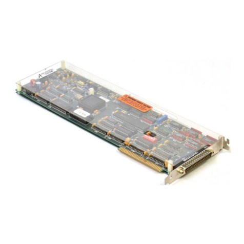
Keithley KM-488-DD User manual

KM-4881DD
IEEE-488 Interface Board
Keifhley MetraByte Corporation
A Subsidiary of Keithle Instruments, Inc.
440 Myles Jandish Boulevard
Taunton, Massachusetts 02780


Part Number: 24407
First Printing: June 1991
Copyright 0 1991
Keithley MetraB te Corporation
440 Myles Stan
CTIsh Boulevard
Taunton, Massachusetts 02780
WARNING
Keithley MetraByte Corporation assumes no liability for damages consequent to the use
of this product. This product is not designed with components of a level of reliability
suitable for use in life support or critical applications.
All rights reserved. No part of this E
ublication may be reproduced, stored in a retrieval
system, or transmitted, in any form y any means, electronic, mechanical, hotoco
recording, or otherwise, without the express prior written permission of I?’ RYetra-
elthley ing,
Byte Corporation.
Information furnished by Keithley MetraByte Corporation is believed to be accurate and
reliable. However, no responsibility is assumed b
atents or other rights o
Y MetraByte Corporation for its use; nor
by third parties which may result from its
implication or otherwise under any patent rights of Keithley
TM
Keithley MetraByte is a trademark of Keithley MetraByte Corporation.
BASICM ts a trademark of Dartmouth College.
IBM@ is a registered trademark of International Business Machines Corporation.
PC, XT, and AT@ are trademarks of International Business Machines Corporation.
Microsoft@ is a registered trademark of Microsoft Corporation.
TURBO” is a trademark of Borland International, Inc.

MOTE:
This equipment has been tested and found to comply with the limits
br a Class B Digital Device, pursuant to Part 15 of the FCC Rules. These
imits are designed to provide reasonable protection against harmful inter-
:erence
in a residential installation. This equipment generates, uses, and can
radiate radio frequency energy and, if not installed in accordance with the
nstructions, may cause harmful interference to radio communications.
Sowever, thereis no guarantee
that
interference will not occur in aparticular
,nstallation. If this equipment does not cause harmful interference to radio
jr television reception, which can be determined by turning the equipment
,ff and
on, the
user is encouraged to try to correct the interference by one or
nore of the following measures:
. Reorient or relocate the receiving antenna
* Increase the separation between the equipment and receiver.
* Connect the equipment into an outlet on a circuit different
from that to which the receiver is connected.
. Consult the dealer or an experienced radio/tv technician
for help.
EK NOTE:
Changes or modifications not expressly approved by the party
responsible for compliance could void the user’s authority to operate this
equipment.
ce NOTE:
Theuse of a non-shielded interface cable with the referenced device
is prohibited.
IV

CHAPTER 1
INTRODUCTION.. ...... ,.................... ................ ............... .. .. .. ..... .. .I -1
1.1 General Introduction ........................ .............................. ........ ................... .............l-1
1.2 Programming Overview ............................................................................................1-2
; .i
115 Manual .........................................................................................l-9
CHAPTER 2
INSTALLATION AND CONFIGURATION ............................ ............ ... ............ ........ 2-1
Part 1-Hardware Installation
2.1 Unpacking and Ins ection ........................................................................................2-2
2.2 Jumpers and Switc Res................................................................................................2-3
2.3 Board Installation .......................................................................................................2-8
2.4 Multiple Board Installation Notes ............................................................................2-10
Part 2 - Initial Software Installation and Configuration
2.5 Initial Software Installation and Configuration ............... ... .... .. ....... ... ... .......2-12
Part 3 - Driver Installation
2.6 Loading the KM-488-DD Driver from AUTOEXEC.BAT .............. ....... ........... .2-24
2.7 Loadin the KM-48%DD Driver from DOS.................. .... .. .................... .. ........2-26
2.8 Unloa cfmg the KM-488-DD Driver from DOS .......................................................2-27
Part 4 -Software Re-Configuration
CHAPTER 3
INTRODUCTION TO PROGRAMMING VIA THE FILE I/O COMMANDS ... .. ...3-1
3.1 The DOS File Interface ...............................................................................................3-1
3.8 Timeout ...............................................................................~........................................3-9
3.9 Buffered ........................................................................................................................3-9
3.10 Trigger ..........................................................................................................................3-10
3.11 Status and Spoll ..........................................................................................................3-10

;:A; I..#&e~nI~teep’t..
...................................................................................................................................................................................................
.3-l 1
.3-12
3.14 Request.. ......................................................................................................................
.3-13
CHAPTER 4
USING THE FILE I/O COMMANDS
4.1 In BASICA.. ................................................................................................................
.4-l
4.2 Additional BASICA Routines.. ................................................................................
.4-4
4.3 In QuickBASIC.. ........................................................................................................
..4-12
4.4 In Microsoft PASCAL ................................................................................................
4-15
4.5 In TURBO PASCAL.. .................................................................................................
.4-20
4.6 In Microsoft C.............................................................................................................
.4-25
4.7 InTURBOC.. ..............................................................................................................
,431
CHAPTER 5
THE FILE I/O COMMANDS .............................................................................................5-l
5.1 Command
5.2 The File Description Format.. ..............................................................................
.5-l
I/O Commands.. ........................................................................................
.5-2
CHAPTER 6
INTRODUCTION TO PROGRAMMING VIA THE CALL INTERFACE
6.1 Accessing the Call Interface.. ...................................................................................
.6-l
6.2 GPIB Terminators .......................................................................................................
6-2
6.3 KCONFIG.. .................................................................................................................
.6-3
6.4 Clear Devices.. ............................................................................................................
.6-4
6.5 Data......................................................................................................
.6-3
6.6 Transmitting
Receiving Data.. .........................................................................................................
.6-3
6.7 KTO.. .............................................................................................................................
6-4
6.8 KBUFD.. ......................................................................................................................
.6-4
6.9 KTRIGGER.. ................................................................................................................
6-4
6.10 KSTATUS and KSPOLL.. ..........................................................................................
.6-4
ii:;; Li&tg;;;;dypF; :::::::::::::::::::::::::::::::::::::::::::::::::::::::::::::::::::::::;::::::::::::::::::::::::::::f55;
6.13 KREQUEST.. ...............................................................................................................
.6-6
CHAPTER 7
USING THE CALL INTERFACE IN BASICA
7.1 Description Format.. ..................................................................................................
.7-5
CHAPTER 8
USING THE CALL INTERFACE IN QUICKBASIC
8.1 Description Format .....................................................................................................8-4
Vi

CHAPTER 9
USING THE CALL INTERFACE IN MICROSOFT PASCAL
9.1 Description Format .................................................................................. ..................9-4
CHAPTER 10
USING THE CALL INTERFACE IN BASICA
10.1 Description Format ......................................................................... ..........................10-4
CHAPTER 11
USING THE CALL INTERFACE IN C
11.1 Description Format ............................... ........................ .... ........... ........................ 11-3
CHAPTER 12
WARRANTY INFORMATION ...................................... .................. .. ......... ..... ...........12-l
12.1
12.2 Warranty .....................................................................................................................12-l
Return to Factory Information ............................................ ......... .. ... ......... ....... .12-l
APPENDIX A - ASCII EQUIVALENCE CHART
APPENDIX B - IEEE-488 TUTORIAL
APPENDIX C - IEEE MULTILINE COMMANDS
APPENDLX D - DEVICE CAPABILITY CODES
APPENDIX E - PRINTER AND SERIAL PORT RE-DIRECTION
APPENDIX F - THE CONFIG.DAT FILE
AI’PENDLX G - ERROR MESSAGES
SUMMARY OF CALLS
SUMMARY OF FILE I/O COMMANDS
GPIB SYSTEM CONFIGURATION WORKSHEET
Vii

LISTOF TABLES
Table l-l. Orderin f Information .................................................................. ............ .......l-9
Table 2-l. Default
Table 2-2. Wait umper and Switch Settings .................................. ............... ............2-4
States..........................................................................................................2-6
Table 2-3. Default
Table Terminator Sequences............................ ........................ ......... 2-19
2-4.
Table 5-l. Assigned DOS Devices .............................................. ..................... 2-23
Lit of File I/O Commands ........................................................... ....... ..........5-2
Table 5-2. Status Strin
Table 7-1. Default hf .......................................................................................................5-52
K
;;;;&;;. -488-DD Operating Parameters ...... ........................ ..................7-3
Table S-2:
~~~ls’~~~~~~~~~~~~~~~~~~~~::~:::~ ::::;::::::::::::;:::::::::::::::::::::::::%;8
Status Strin .......................................................................................................8-76
Table 9-1. Default Khk
Table 9-2. Status Strln -488-DD Operating Parameters ................................................ .9-2
........................................................... ............ ........... ............... .9-75
Table 10-l. Default K
Table 10-2. Status Strin -488-DD Operating Parameters ........................................ .......8-2
Table 11-2: Stabs S~~~-~~-~-~ ... ....................................... ............... ... ... ... ............ .8-78
Table 11-1 Default K -488-DD Operating Parameters ................................ ...............11-2
.................................... .... . . 11-61
LISTOF FIGURES
Figure l-l. .........................................................................
Figure l-2. KM-488-DD Block Diagram.. l-2
File I/O Interface - Direct Path.. ......................................................
l-4
Figure l-3. File I/O Interface - Direct Output
Figure l-4. Input Path.. .........................................................
l-5
File I/O Commands - Buffered Output Path.. ............................................l-6
Figure l-5. Call Interface Path.. .........................................................................................
l-7
Figure 2-1. Location and Switches.. .............................................................
.2-3
Figure 2-2. Base of Jumpers
Address Switch.. ....................................................................................
.2-4
Figure 2-3. Interru z t Selection.. ........................................................................................
.2-5
Figure 2-4. Base A dress Selection.. ................................................................................
.2-5
Figure 2-5. I/O Wait State Selections.. ............................................................................
.2-6
Figure 2-6. Interrupt Level Jumpers.. ..............................................................................
.2-7
Figure 2-7. DMA Level Jumpers.. ....................................................................................
.2-7
Figure 2-8. Clock Source
Figure 2-9. Software Jumpers..
Installation Screen..
..........................................................................................................................................................
.2-S
.2-13
Figure 2-10. Selecting Langua es..
5 ....................................................................................
.2-13
Figure 2-11. Select Command ..................................................................................
.2-15
Figure 2-12. Device Confi tyle
ration Screen..
Figure 2-13. Selecting the ?z .....................................................................
.2-15
rd Option.. ..........................................................................
.2-16
Figure 2-14. Selecting the Default EOL and Bus Terminators.. ....................................
.2-19
Figure 3-l. Terminators used with the File I/O Commands.. .....................................
.3-5
Viii

KM-488-DD Programming Guide Introduction
CHAPTER I
/NTRODUCT/ON
1.1 GENERALINTRODUCTION
Keithley MetraByte’s KM-488-DD is an IEEE-488 interface board which allows programs
written on an IBM@ PC/XT/AT/386~ or IBM ES2models 2S/30 to communicate with the
IEEE-488 bus. The KM-488-DD conforms to the 1978 IEEE-488 (GPIB) standard and thus, is
compatible with other IEEE-488 products currently offered by many other manufacturers.
Up to fourteen other devices may be connected to the IEEE-488 bus, including instruments,
printers, and other computers.
The KM-488-DD’s design includes a Wait State Generator to adjust the bus timing. This
allows the KM-488-DD to perform within the operating specifications of the GPIB controller
chip, even on the fastest 386 or 486-based PC’s, The KM-488-DD can also be configured to
generate interrupts on any of 6 interrupt request lines and DMA transfers on channels 1,2,
or 3. Figure l-l provides a functional block diagram of the KM-488.DD.
Keithley MetraByte’s software allows the KM-488-DD to be accessed either through the use
of the File I/O Commands or from the Call Interface, both of which can be used in programs
written in QuickBASIc?, BASICA, MicrosofP C, TURBOTMC,TURBOTMPASCAL, and
MicrosofP PASCAL. The KM-488-DD is also compatible with a variety of third-party soft-
ware packages, such as Keithley Asyst’s Asystant GPIB.
l-l

Introduction KM-488-DD Programming Guide
Figure l-l. KM-488-DD Block Diagram
1.2 PROGRAMMING OVERVIEW
Keithley MetraByte’s driver for
the
KM-488-DD is a Terminate and Stay Resident driver
which provides a means of transferring data between your application program and the
GPIB bus. Once the driver is installed, the application program can accessit either through
the DOS file facility or directly by program calls.
Programs which must be optimized for GPIB throughput should employ the CALL inter-
face. If throughput is
not
a consideration then the choice between the CALL interface and
the FILE interface is a matter of personal preference.
Programmers familiar with using file I/O (Opening files and transferring data between the
program and files) may be more comfortable with the FILE interface. The File I/O Com-
mand interface tends to distance the programmer a bit
more
from the “mechanics” of the
GPIB bus than the CALL interface. Programming
can
be as simple as writing strings to a
file opened for output or reading strings from a file opened for input. The File I/O Com-
mands are “English-Language” like representations of the GPIB commands. Through the
use of the CONFIG program, you can create series of facts about a particular GPIB device
(i.e., bus address and terminators) and refer to it as a Named Device through the File I/O
1-2

KM-488-DD Programming Guide Introduction
Command
Interface. For example, the GPIB address 12 could have the name “SCOPE”,
which when used implies the GPIB address 12 and whatever terminators were associated
with “SCOPE”.
With the exception of the fact that Named Devices cannot be referred to directly through the
CALL interface, for most of the File I/O Commands there is an a CALL which performs an
equivalent function.
The following two sections are provided for those who wish to know a bit about how the
driver functions. You do not have to read these sections in order to employ the driver.
Most of what is described occurs automatically without the programmeis knowledge.
FILEl/O COMMAND INTERFACE
To employ the File I/O Command Interface, the programmer will use the facilities of
his/her particular programming language to open a file for outputting to the driver and a
file for inputting from
the driver.
Driver Commands/Direct Data Output
Transfers between the application program and the GLIB bus will be initiated by the appli-
cation program sending
a command
to the driver. Commands take the form of character
strings which are written to the driver output file opened through DOS (Groups of
commands and also data may be placed in one string; but the maximum string length is 255
characters.). This
has the
effect of calling DOS with a “Write to Device” request as
shown
in
Figure 1-2. DOS moves the character string
one
character at a time from the application pro-
gram into the command parser of the KM-48%DD device driver. DOS must make two calls
to the driver for each character
that
is transferred. This command transfer process is
relatively time consuming.
Once
the
command is in the driver parser, the driver must interpret the command and jump
to a particular set of code within the driver which will carry out
the
appropriate function.
If the command is to output data to the GPIB bus, the data can be included in the string
along
with the command and follows the same path as the command through DOS. The
amount of data than can be sent in this manner is limited by the string length and must also
pass through DOS character by character. The one exception is the “OUTPUT DEVICE;
data” command in which data can consists of an infinite number of characters. OUTPUT’s
of this type are halted when the EOL character sequence is encountered in the data stream
of
characters.
l-3

Introduction KM-488-DD Programming Guide
Direct Data Entry
To
return
information from the driver, the application program sends a command to the
driver requesting data in the manner described above and then initiates an input from the
driver. For example, the returned data may pertain to the status of the driver or be
obtained from the GPIB bus. In either case,the data is buffered in the driver awaiting an
INPUT action.
To bring the data into
the
application program, the program does an input from the file that
was opened for driver input as shown in Figure l-3. This amounts to employing the DOS
“read from device” request and data will be returned in the same manner as it was sent,
character by character. It is important to input data resulting from a command before issu-
ing a second command which will return data. Otherwise, a driver error will occur.
1-4

KM-488-DD Programming Guide Introduction
-
DATA
+y SPIT
Figure 13. File I/O Interface- Direct Input Path
BufferecVDMA Dafa l/O
The amount of data that can be transferred by Direct I/O is limited (except in the case of
“OUTPUT 05; data” and the transfer mechanism is relatively slow. Both these deficiencies
can be overcome by using buffered transfers. In this case, the command sent to the driver
contains information about the location in memory where data will sent to/received from
the GPIB bus. Once set up, the data will move directly between the program memory and
the GPIB bus via the KM-488-DD’s hardware. Figure 1-4 illustrates the case of data send. A
data entry would appear similar with the data passing through an ENTER routine in the
opposite direction.
In normal buffered transfers,
the
driver transfers the data between memory and
the
GPIB
bus via the KM-488-DD’s hardware. The PC’s DMA facility
can
be used to make a buffered
transfer. Although buffered transfers are generally faster, there will be some overhead in
setting them up so direct transfers are probably just as efficient if only small amounts of
data are involved. All transfers through
the
CALL interface are buffered.
1-5

Introduction KM-488-DD Programming Guide
Figure 1-4. File I/O Commands-Buffered Output Path
To employ the CALL interface, the programmer uses the call facility of his/her particular
programming language. Typically, a Keithley MetraByte provided library(ies) or loadable
module is incorporated when building the application with a supported language. Appro-
priate batch files are provided to assist in remaking these libraries/modules.
When a call is made, the appropriate parameters contained in
the
call are placed
on the
cal-
ler’s stack for use by the driver and the program enters the code of the interface module as
diagrammed in Figure 1-5. The interface module for the particular language verifies that
the driver is installed and jumps directly to the driver command code which performs the
desired function. The amount of time required to get to the driver command code from the
application by means of
the
call interface is much less than that by means of the file inter-
face.
If data is to be transferred, then the call parameters include addresses of location(s) in pro-
gram memory where the data is to be found and/or sent. As opposed to the File I/O Com-
mand Interface,
the
Call Interface always uses the faster buffered transfers (with or without
DMA).
l-6

KM-488-DD Programming Guide
m-
Figure l-5. Call Interface Path
1.3 SPECIFICATIONS
Specifications for the KM-488-DD are as follows:
Dimensions: One Short PC Slot size
Weight: .29 lb.
Data Transfer Rate:’ > 300 KB per second
IEEE Controller Chip: NEC
@‘D7210
Power Consumption: < 650 mA
Operating Temperature: O’to50”C
StorageTemperature: -2o’to +7O”C
Humidity: 0 to 90% non-condensing
tGovemed by the slowest device on the GPIB bus.
1-7

Introduction KM-488-DD Programming Guide
Wait States:
I/O BaseAddress:
DMA Capability:
Interrupt (IRQ) Address:
DeviceInterface Capabilities
Supported
Switch Selectable
1,2,3or 4
Switch Selectable
&HO2El, &H22El, &H42El, or &H62El
Switch Selectable
Channels 1,2,or 3 shareable
Switch Selectable
Levels 2 through 7
SHl, AHI, T6, TEO,L4, LEO,SRI, Pl’O, RLO,DCl, DTl, CO,
El
12,
Controller Subsets: Cl, C2, C3, C4, and Cl0
Terminator: Software Selectable characters and/or EOI
1.4 ORDERING INFORMATION
Table l-l provides additional ordering information, in the event that you need additional
KM-488-DD’s or appropriate cables.
1-8

KM-488-DD Programmlng Guide Introduction
Part Number
KM-488-DD
KM-488-DD/3.5
KM-488-DD-BRD
CGPIB-1
CGPIB-2
CGPIB-4
Tablel-l. Ordering Information
Description
Includes the KM-488-DD IEEE-488 Interface Board, Software (on
5.25” disks), and appropriate documentation.
Includes the KM-488-DD IEEE-488 Interface Board, Software (on
3.5” disks), and appropriate documentation.
Includes
the
KM-488-DD IEEE-488 Interface Board and appropri-
ate documentation.
1meter IEEE-488 cable.
2 meter IEEE-488 cable.
4meter IEEE-488 cable.
1.5 HOW TO USETHISMANUAL
This manual provides you with the information necessary to install and program the KM-
488-DD. It assumes you are familiar with the language in which you are developing your
application program. It also assumes that you are familiar with the GLIB protocol.
Chapter 2, “Installation and Configuration”, provides all the necessary information for you
to get the KM-488-DD “up and running”. It details how to unpack, inspect, and install the
KM-488-DD. It also describes how to install and configure the software. Jumper and switch
setting information is provided in case you should need to
change the
factory-selected
defaults.
Chapters 3 through 5 describe the use of the File I/O Command Interface. Chapter 3 pro-
vides introductory information. Chapter 4 describes how to implement the commands in
each supported language: BASICA, QuickBASIC, C, Microsoft PASCAL, and TURBO
PASCAL. Chapter 5 describes each command in detail.
Chapters 6 through 11described the use of the Call Interface. Chapter 6 provides introduc-
tory information. Chapters 7 through 11 provide a detailed description of each routine and
how
it is called from each of
the
languages supported: BASICA, QuickBASIC, C, Microsoft
PASCAL, and TURBO PASCAL.
l-9

Introduction KM-488-DD Programming Guide
Chapter 12,
“Warranty
Information”, describes Keithley MetraByte’s warranty and gives
instructions for returning the board to the factory.
The appendices contain additional useful information. Appendix A contains an ASCII
Equivalence Chart. This gives hexadecimal and decimal equivalents for the ASCII 128 Char-
acter
Set. Appendix B is an IEEE-488 tutorial. Appendices C and D contain supplementary
information to the IEEE-488 tutorial (Device Capability Identification Codes and IEEE
Multiline Commands). Appendix E describes how to use the KM-488-DD Printer and COM
Port Re-Director. Appendix Fdescribes the CONFIG.DAT file. Appendix G lists and
describes the Error Messages.
l-10

KM-488-DD Programming Guide Software Installation and
Configuratlon
CHAPTER2
INSTALLATION AND CONFIGURATION
This chapter outlines all of the steps necessary to get your KM-488-DD “up and running”.
The chapter is broken up into four parts;
. PCS’/I - Hardware
Insfcrlloti~n.
This section describes how to unpack and inspect the
KM-488-DD, set its jumpers and switches, and install the KM-488-DD board(s).
.
Part 2 - Initial SofTwareInstallation and Configuration.
This section describes those
procedures which are to be used the first time you install and configure the KM-
488-DD software.
.
Par/
3 - Driver
insfallafion.
Once
you have configured the software, you will need to
load the driver software before you can use the KM-488-DD. This section describes
how to load the driver from your AUTOEXECBAT file or
manually from the DOS
prompt.
.
Parf4 - Soffware Re-Conllgumtion.
Thii section describes how to change your sys-
tem configuration once it has already been made.
Once you have installed the KM-488-DD and configured the software, you may want to run
the HEEECMD.BAS program. This program will allow you to send FineI/O Commands
and seethe results. Note, however, that this program can
only
be
run
in a single board
set-up. To run this program, make sure that BASICA is installed and from the DOS prompt,
type: BASICA KIEEECMD.
2-l

Software Installation and
Configuration KM-488-DD Programming Guide
PART 1- HARDWARE INSTALLATION
Before you can use your new KM-488-DD board you must unpack and install it correctly.
To do this, follow these steps:
.
Unpack and
inspect the KM-4&I-DD. This seems like a trivial step; however it is cru-
cial that your board be unpacked correctly. This information is described in section
2.1.
.
Set the Jumpers andSwitches on the KM-488-DD.
This step is unnecessary if you elect
to use the factory selected defaults
shown
in Table 2-1. If you want to change any of
these settings, consult section 2.2.
. lnsfa//
the KM-488-DD.
The KM-488-DD is installed in
the same manner as any other
peripheral board. If you are unfamiliar with this process, follow
the
instructions in
section 2.3.
If you are installing multiple KM-488-DD’s in the same GPIB system, be sure to read Section
2.4, Multiple Board Installation Notes.
2.1 UNPACKlNG AND INSPECTION
Confirm that
each
item on the packing list
has
been shipped. It is a good idea to retain the
outer packing material in the
event
that the board must be returned to the factory for repair.
1. Then, if you haven’t already done so, unpack the board down to its anti-static
packaging.
2. Hold the board (in its anti-static bag) in one hand. Place the other hand firmly on a
metal portion of the system chassis. This procedure eliminates static electricity
build-up, thus preventing any possible damage to the board.
3. After allowing a moment for static electricity discharge, carefully unwrap the board
from the anti-static material.
4. Inspect the board for any possible shipping damage. If any sign of damage is detected,
return
the
board to the factory as described in section 12.2.
You are now ready to set the jumpers and switches on the KM-488-DD.
2-2
Table of contents
Other Keithley Computer Hardware manuals

Keithley
Keithley DAS-1800ST Series User manual

Keithley
Keithley 7075 User manual

Keithley
Keithley KM-488-ROM User manual

Keithley
Keithley 7038 User manual

Keithley
Keithley DAS-1700 Series User manual

Keithley
Keithley DAS-TC User manual

Keithley
Keithley PDISO-8 User manual

Keithley
Keithley 7063 User manual

Keithley
Keithley 7012-S User manual

Keithley
Keithley 7020-D User manual
Popular Computer Hardware manuals by other brands

Quatech
Quatech DP-PCIE-100 user manual

Plura
Plura QC & Engineering 3G Series operating instructions

Lexicon
Lexicon MPX 5 V1.1 - REV installation instructions

ekwb
ekwb EK-FB KIT GA X58 (UD7) INSTALLATION AND MOUNTING MANUAL

Rosewill
Rosewill PB240-RGB Quick user guide

Bosch
Bosch MADI Card Plus Series user manual