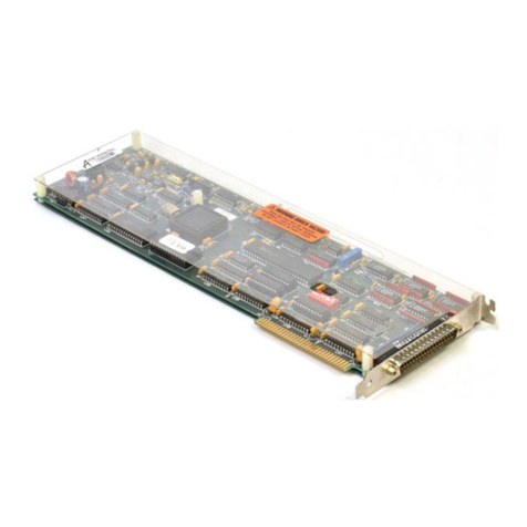
Keithley KM-488-ROM User manual

KM=4881ROM
Keithley Data Acquisition KeitNey MetraByte/Asyst

FCC Class B Compliance
NOTE: This equipment has been tested
and
found to comply with the limits for a Class B
Digital Device, pursuant to Part 15 of the FCC Rules. Theselimits are designed to provide
reasonable protection against harmful interference in a residential installation. This
equipment generates,uses,and can radiate radio frequency energy and, if not installed in
accordancewith the instructions, may causeharmful interference to radio communications.
However, there is no guarantee that interference will not occur in a particular installation. If
this equipment doesnot causeharmful interference to radio or television reception, which can
be determined by turning the equipment off and on, the user is encouraged to try to correct
the interferenceby one or more of the following measures:
l
Reorient or relocatethe receiving antenna.
l
Increasethe separation between theequipment and receiver.
l
Connect the equipment into
an
outlet on acircuit different from that to which the receiver
isconnected.
l
Consult the dealer or anexperiencedradio/tv technician for help.
NOTE:
The useof a non-shielded interfacecablewith the referenceddeviceis prohibited.

User Guide
for the
KM-488-ROM
IEEE-488 Interface
Board
R~vislon A - March $99,
Copyrlghl Kelthley Data AC ulsltlon 1991
aPart Number: 244 9
KElTHLEY DATA ACQUISITION - Kelthley MetraSytelAsyst
440 Myles Standish Blvd., Taunton, MA 02790
TEL. 609/99%?0W. FAX MW990-0179
- 11,-

warrantyInformation
All products manufactured by Keithley Data Acquisition are warranted
against defectivematerials and worksmanship for aperiod of one year
from the date of delivery to the original purchaser. Any product that is
found to bedefectivewithin the warranty period will, at theoption of
the manufacturer, be repaired or replaced. This warranty doesnot apply
to products damaged by improper use.
warning
Keithley Data Acquisition assumesno liability for damages
consequent to the use of this product. This product is not designed
with components of alevel of reliability suitable for use in life
support or critical applications.
Disclaimer
Information furnished by Keithley Data Acquisition is believed to be
accurateand reliable. However, Keithley Data Acquisition assumesno
responsibility for the useof suchinformation nor for any infringements
of patentsor other rights of third parties that may result from its use. No
licenseisgranted by implication or otherwise under any patent rights of
Keithley Data Acquisition.
Copyright
All rights reserved. No part of this publication may be reproduced,
stored in a retrieval system,or transmitted in any form by any means,
electronic, mechanical,photoreproductive, recording, or otherwise
without the expressprior written permission of the Keithley Data
Acquisition.
Note:
Keithley MetraByteWis atrademark of Keithley Instruments.
Basi? is atrademark of Dartmouth College.
IBM@is a registered trademark of International BusinessMachines
Corporation.
PC,XT, AT, PS/Z,and Micro Channel Architecture@aretrademarks of
International BusinessMachinesCorporation.
Microsoft@is aregistered trademark of Microsoft Corporation.
Turbo C@isa registered trademark of Borland International.
-iv-

Contents
CHAPTER 1 - INTRODUCTION
1.1
1.2
1.3
1.4
Overview ................................... .1-l
Specifications ................................ 1 1 1 1 .I-2
Ordering Information ................................. . l-3
HowToUseThisManual.. ............................. .l-3
CHAPTER 2 - INSTALLATION
2.1
2.2
2.3
2.4
2.5
2.6
2.7
2.6
General ........................................
Unpacking & Inspecting
.2-i
Software Installation . 1 1 1 1 1 1 1 1 1 1 1 1 1 1 1 1 1 1 1 1 1 1 1 1 1 1 1 . ’ . .2-l
.2-l
Switches 3 Jumpers ............................. : : : : .2-2
Board Installation ...................................
Configuration Of The EEPROM .2-7
Reloading The
EEPROM
........................ : : : : : : : : : : : : : : : : .. .2-a
2-10
Multiple Board Installation Notes ........................... 2-10
CHAPTER 3 - INTRODUCTION TO CALLABLE ROUTINES
3.1
3.2
3.3
3.4
3.5
3.6
3.7
3.6
3.9
Initializing The KM-486-ROM. ............................ .3-3
Selecting The Receive & Transmit Terminators
Transmitting Commands&Data. ........... : : : : : : : : : : : : : : : : .. .3-3
.3-5
Reading Data ..... ... ..
Transmitting/Receiving Data Via
DMA
................. : : : : : : : : : : : : : : : : 3-11
3-14
Checking Device Status
..
3-15
Low-Level Routines. ...............................
................................. 3-17
Board Configuration
Routines ............................ 3-16
Multiple Board Programming Notes ......................... 3-19
CHAPTER4 - PROGRAMMING IN BASICA OR GWBASIC
4.1
4.2
4.3
General ........................................ .4-i
Description Format For Routines. .4-3
Routines. . .... .. ........................ : : : : : : : : : : : : : : : : .. .4-3
CHAPTER 5 - PROGRAMMING IN QUICKBASIC
5.1
5.2 General . . . . . . . . . . . . . . . . . . . . . . . . . . . . . . . . . . . . . .5-i
5.3 Description Format For Routines. . . . . . . . . . . . . . . . . . .5-3
Routines. . . . . . . . . . . . . . . . . . . . . . . . . . . .5-3
CHAPTER 6 - PROGRAMMING IN TURBO PASCAL
6.1
6.2
6.3
General . . . . . . . . . , . . . , . . . . . . . . . . . . . . . . . . . . . .6-l
Description Format For Routines. . . . . .
Routines. . . . . . . . . . . . . . . . : : : : : : : : : : : : : : : : : ’ . .6-2
. .6-3

Contents
CHAPTER 7 - PROGRAMMING IN C
7.1 General. ........................................ 7-l
7.2 Description Format For Routines ........................... 7-3
7.3 Routines ........................................ 7-3
CHAPTER6 - FACTORYRETURNS
APPENDICES
Appendix A - ASCII Code Chart
Appendix B - IEEE Tutorial
Appendix C - IEEE Multiline Commands
Appendix D - Device Capability Codes
Appendix E - Printer & Serial Port Redirection
n DD
- vi -

Chapter 1
INTRODUCTION
1.1 OVERVIEW
The KM4?8-ROM is an IEEE488 interfaceboard that allows programs written on IBM
PC/XT/ATs, IBM I’S225/3Os,or compatibles
to communicate
with an IEEE488 bus. This
Board complies with the 1978IEEE488 standard and is thus compatible with other IEEE488
products. Up to fourteen other devicesmay beconnectedto the IEEE488 bus, including
instruments, printers, and other computers. The KM48-ROM
comprises a board,
software,
and documentation.
Figure l-l is ablock diagram of the KM-488-ROM board.
Figure l-l. KM-4&WROh4Block Dlagram
The Kh4488-ROM design includes a Wait StateGenerator to adjust bus timing, allowing
performance within operating specificationsof the GLIB controller chip on the fastestPCs.
This Board canalsogenerateprogrammed interrupts on any of sixinterrupt request lines and
DMA transferson Channels 1,2, and 3. Selectionof messageterminators and timeouts is
modifiable to allow communication with GPIBdevicesusing non-standard charactersand
timeouts.
INTRODUCTION 1 - 1

1.2
The KM-488-ROM alsofeaturesan 8-KBEEPROM(Electrically ErasableProgrammable Read
Only Memory) containing firmware routines callable from aBASICA program. These
routines perform the IEEE-488transfer functions. KM-488ROM software libraries allow
accessto routines from programs in QuickBASIC, Microsoft C,and TURBO PASCAL.
Examplesfor eachlanguage are included.
SPECIFICATIONS
Dimensions:
DMA Level:
Interrupt URQ)Capability:
Data Transfer Rate(Governedby the
slowest device):
IEEEController Chip:
Power Consumption:
Operating Temperature:
StorageTemperature:
Humidity:
Wait States:
Net Weight:
ROM BaseAddress:
I/O BaseAddress:
DeviceInterfaceCapabilities
Supported:
OneShort PCSlot size.
Channels1,2,3, or None (JumperSelectable).
Levels2through 7or None (JumperSelectable).
> 300Kb per second.
NEC7210.
< 500mAmps.
0 to 50 T.
-4to 158‘F (-20to +70“0.
0 to 90%noncondensing.
1,2,3, or 4 (Switch Selectable).
.31
lb (.14kg).
Switch Selectable.
Switch Selectable.
SHl, AHI, T5,TE5,L.3,LE3,SRl, RLl, PPl, PP2,
DCl, DTl, Cl-5, E1/2. (SeeAppendix D for
clarification.)
1-2 KM-488~ROM USER GUIDE

1.3 ORDERING INFORMATION
PARTNUMBER DESCRIPTION
KM-488-ROM Includes the KM-488-ROM IEEE-488InterfaceBoard,
Software (on 5.25”disks), and appropriate
documentation.
KM-488-ROM/3.5 Includes the KM-488-ROM IEEE488 Interface Board,
Software (on 3.5”disks), and appropriate
documentation.
CGPIB-I 1meter IEEE-488cable.
CGPIB-2 2 meter IEEE-488cable.
CGPIB-4 4 meter IEEE-488cable.
1.4 HOW TO USE THIS MANUAL
This manual provides the information necessaryto install and program the KM-488-ROM.
The manual assumesyou are familiar with the language in which you aredeveloping your
application program; it alsoassumesyou are familiar with the IEEE-488protocol.
Chapter 2, Installation, details how to unpack, inspect,configure, and install the KM-488
ROM and how to copy the accompanying software. Additionally, Chapter 2describeshow to
install the KM48EROM software and to configure the EEPROMand reload EEPROM
software. There arealsonoteson using multiple boards in one system.
Chapter 3, Zntroductfanfothe
CaRableRoutines,
provides abrief functional description of each
KM488-ROM Interface Routine.
Chapter 4, Programmingthe
KM-488-ROM,
provides a detailed description of eachKM-488-
ROM InterfaceRoutine and how it iscalled from eachof the supported languages: BASICA,
QuickBASIC, C,and TURBO PASCAL.
Chapter 5, FactoryReturns, givesinstructions for returning the board to the factory.
The appendicescontain additional useful information. Appendix A contains an ASCII
EquivalenceChart. This giveshex and
decimal
equivalents for the ASCII 128Character set.
Appendix Bis an IEEE-488tutorial. Appendix C provides an explanation of the Device
Capability Identification codes. Appendix D provides across-referencechart of IEEE
Multiline Commands. Appendix Edescribeshow to usethe KM488-DD Printer Port Re-
director.
INTRODUCTION 1 - 3

0
l-4 KM-488-ROMUSERGUIDE

Chapter 2
INSTALLATION
2.1 GENERAL
Installation begins with procedures for unpacking and inspection followed by
recommendations and instructions for software. Next is a sectionon switch and jumper
settings. Board installation isthe next step,followed by EEPROMconfiguration.
2.2 UNPACKING 81INSPECTING
After removing the wrapped Board from its outer shipping carton, proceed asfollows:
1. Beforeunwrapping the Board,placeone hand firmly on abare-metal portion of the
computer chassisto discharge staticelectricity from yourself and the Board (the computer
must beturned Off but grounded).
2. Carefully removethe Board fromits anti-static wrapping material. You may wish to save
the wrapping material for possiblefuture use;if so,storeit in a safeplace.
3. Inspect the Board for signsof damage. If any damageis apparent, return the Board to the
factory.
4. Check the remaining contentsof your packageagainst the packing list to be sureyour
order is complete. Report any missing items to the factory immediately.
5. When you are satisfiedwith preliminary inspection, you areready to configure the Board.
Referto the next sectionfor configuration options.
2.3 SOFTWARE INSTALLATION
Backing Up The Distribution Software
As soonaspossible,make aback-up copy of your Distribution Software. With one (or
more,asneeded) formatted disketteson hand, placeyour Distribution Sofhvarediskette in
your PC’sA Drive and log to that drive by typing A: . Then, makeyour backup using the
DOS
COPY
or
DISKCOPY
command, asdescribedin your DOSreferencemanual
(DISKCOPY ispreferred becauseit copiesdiskette identification, too).
installing The Distribution Software
Install the KM-488-ROM Distribution Software on your computer’s hard drive using the DOS
COPY command.
INSTALLATION 2 - 1

NOTE: If you areusing BASICA and the factory default settings,you may run the KM-
4%ROM board without installing any software. Instead,proceed to Section2.4.
To install the software:
1. Turn on your PCand its display. You should seethe standard DOS-levelprompt.
NOTE: If you install exampleprograms written in multiple languages,you may want to
createadirectory for eachlanguage. (This is the way the Distribution Software is
organized.)
2. The following instructions createadirectory named
KM488R. Type md \Rld488R
3. Changeto the KM488Rdirectory by typing cd \KM488R
4. Placea KM-4&%ROM Diskette into the floppy drive (assumethis is Drive a:)and type
copy a:*.*
Repeatthis stepfor eachdisk and/or subdirectory, until copying is complete.
Distribution Software Contents
Your Distribution Software contains the file
FILESDOC
,an ASCII text file readablewith any
text editor or with the DO!?
TYPE
command. FlLES.DOClists and briefly describesall files
in the Distribution Software.
The README.DOC File
To learn of last-minute changes,be sure to read the ASCII file
READMEDOC
2.4 SWITCHES & JUMPERS
Factory Settings
The KMG%-ROM contains three DIP switches and two jumper banks (seeFigure 2-l). These
switches and jumpers are factory-configured to work with most PC configurations. Table 2-l
lists the factory selections.
Table 2-1. Factory Switch & Jumper Settlngs
SWITCH/JUMPER FACTORY SE’ITING
I/O BaseAddress: 2b8h.
ROM BaseAddress: CCOOhROM Enabled.
I/O Wait State: 1Wait State;SystemController Enabled; EEPROM
Write Disabled.
Interrupt (IRQ) Level: Disabled.
DMA Level: Disabled.
2-2 KM-488~ROM USER GUIDE

For assistancewith setting the switchesor thejumpers, run the INSTALL program. This
program illustrates the correctswitch settingsfor your selections. To run the INSTALL
program, make sureyou arein theappropriate directory and type INSTALL at the DOS
prompt. Then, follow program directions.
Figure 2-1. Switch and Jumper Locatlons
Switches
There arethree DIP switch blocks on the KM48-ROM board, asfollows: Wait State(Sl), I/O
BaseAddress (S2),and ROM BaseAddress 63). The switches are factory-set to work with
mostPCconfigurations (seeTable 2-l for settings).
NOTE: If you areusing BASICA and changethe I/O BaseAddress DIP switch settings,be
sure to run the configuration program, CONFIG. SeeSection2.7.
I/O Base Address Switch
Setting an I/O BaseAddress enablesthe KM-488-ROM to communicate with the PC. You set
an I/O BaseAddress for the Board by setting the sevenpositions of Switch S2for the assigned
address. Setting aswitch position to ON puts the corresponding addressline ata logic 0
(low).
The KM-488-ROM requires aseriesof 8 I/O port addressesthat begin with the I/O Base
Address. Therefore,be sureto selectan I/O BaseAddress on an B-byteboundary that does
not conflict with other devicesin your computer (refer to your PCmanual for the I/O address
list to determine availablespaces).
Figure 2-2shows examplesof I/O BaseAddress settings. Note that the factory-set Base
Address is 288hex; the I/O ports occupy the addressrange 288 - 2BfHex.
INSTALLATION 2-3

FIgore 2-2. Examples of l/O Base Address SeftlngS
ROM Base Address Switch
This switch determines whether the ROM memory is to beenabled and, if so,where within
the first 1MB of PCmemory it is to belocated. Enablethe ROM if you are programming in
BASICA. The ROM BaseAddress Switch 63) is an B-position DIP switch.
Sevenof the S3positions (1- 7)to selectthe ROM BaseAddress. Position 8enables/disables
the ROM. Setting a position at ON puts the corresponding addressline to alogic 0.
To enableor disable the ROM, set53Position 8 asshown in Figure 2-3.
This position should be ON only if the KM-W-ROM is used with
BASICA software.
Flgure 2-3. Enabllng the ROM ~%B,EO %&LED
Somealternative ROM BaseAddress switch settingsare shown in Figure 2-1. The default
BaseAddress is CC00hex. Besure to selectan 8KB addressspacethat is within the first 1MB
of PCmemory and not occupied.
Flgure 2-4. ROM Base Address Selectlon
If you are
unsure
which addressto assignto the EEPROM,usethe MEMMAP program
provided with the KM-488-ROM. This program scansyour computer’s memory and
determines what memory areasare available. To invoke the MEMMAI’ program, switch to
the appropriate directory and type m . Choosean unoccupied addressspace.
2-4 KM-488-ROM USER GUIDE

Wait State Switch
Switch 1 (Sll configures Wait Statesand the SystemController ON= 0
Mode, and it enablesMemory Write Protection. Sl is a4-position
DIP switch (seeFigure 2-5). Setting aposition to ON puts the
corresponding addressline at signal low (logical 01.Two positions
(1and 21selectthe wait states.
Flgure 2-5. WeltState Switch.
Configure the SystemController function using Position 3and the EEPROMprotection using
Position 4.
I/O Waif States
The KM-B&ROM design includes a switch-selectablewait-state generator. A selectableWait
Stateinsures optimum performance and reliable operation at the differing bus clocksfound in
PCs. The default number of Wait States(11should becorrect for most PCs. vowever, if,youf
data isgarbled or your program crashes,you may need to adjust
the number of Wait States. Somegeneral guidelines are presented
in Table2-2. Selectthe number of Wait Statesby setting Positions
1and 2 (marked Wait State)on the DIP switch. You may program ‘03 911’1
, w*,,STATE , w*l,STITFS
the KM468-ROM to generateone,two, three,or four Wait States
during
I/O. Note that the number of memory Wait Statesis
automatically setto avalue which is onelessthan the I/O Wait
States. To selecta number other than the default, setthe switches
to oneof the positions shown in Figure 2-6.
iE~Yg~
2WNTsTME9 4WITSTATES
Figure 2-6. t/O
Walt
State Seiectlons
Table 2-2. Welt States
BUSCLOCK FREQUENCY NUMBER OF WAIT STATES
<=5MHz
1(default).
5MHz <ticq <8MHz
2.
8MHz <freq < 10MHz
3.
10MHz <freq
4.
System Controller
This switch determines whether or not the KM488-ROM will actasaSystemController. If
the KM-488-ROM isa SystemController, it hasthe ability to assertthe IFC or REN lines.
Position 3 cmthe Wait StateDIP Switch determines whether
3 ON
the KM-438-ROM isacting asaDevice/Controller or aSystem
Controller. Valid selectionsare shown in Figure 2-7. ON i ON = 1
Figure 2-7. Device Mode Selection II 1’
DEVICE OR SYSTEM
CONTROLLER CONTROLLER
INSTALLATION 2 - 5

Memory Write Enable
Positlone4 on the Wait StateDIP Switch enablesor disables
writes to the EEPROMon the KM488-ROM. Valid selections
are shown in Figure 2-8.
Flgure2-8. EEPROM Enable Selection EEPROMWR,TE EEPROMWRITE
ENABLED DlSABLED
This switch should normally beat DISABLE. It should beat ENABLED only when initializing
or configuring the EEPROMBASICA support software.
Jumpers
The KM-ltlE-ROM contains two jumper blocks. Theseblocks selectthe Interrupt Level and
DMA Level.
Selecting an Interrupt Level
The KM-@&ROM is capableof interrupting the PC. The Interrupt Level (IRQ) Jumper (Jll
defines the Interrupt Level. Valid Interrupt Level selections(2through 7 and none) and the
jumper positions are shown in Figure 2-9.
Figure 2-9. Interrupt Level (Ml) Jumpers
Selecting a DMA Level
DMA (Direct Memory Access)is a PCfacility for speedingup data transfer from aperipheral
to the computer. Selectan appropriate DMA levelusing the DMA LevelJumpers. Referto
2-6 KM-488-ROM USER GUIDE

Figure 2-10for jumper positions.
F/gum 2-10. DMA Level Jumpers
2.5 BOARD INSTALLATION
To install the KM-488-ROM in a PC,proceedasfollows:
1. Turn Off power to the PCand all attachedequipment.
WARNING!
ANY ATTEMPT TO INSERT OR REMOVE ANY ADAPTER BOARD
WITH COMPUTER POWER ON COULD DAMAGE YOUR
COMPUTER!
2. Removethe cover of the PC.
3. Choosean availableoption slot. Loosenand remove the retainer screw at the top of the
blank adapter plate. Then slide the plate up and out to remove.
4. Beforetouching the Board, placeonehand on any metallic part of the PCchassis(but not
on any components) to dischargeany staticelectricity from your body.
5. Make sure the Board switcheshavebeenproperly set(refer to the configuration sections).
6. Align the Board connector with the desired accessoryslot and with the corresponding
rear-panel slot. Gently pressthe Board into the socketand securewith the retainer screw
for the rear-panel adapter-plate.
7. Replacethe computer cover.
8. Plug in all cords and cables. Turn the power to the computer back on. You are now ready
to makeany necessarysystemconnections.
INSTALLATION 2 - 7

If you aredeveloping KM488-ROM application programs in C, TURBOPASCAL or
QuickBASIC, the installation processis now complete. However, if you are developing
programs in BASICA and havechanged the factory default settings,you must to run the
EEI’ROM configuration program CONFIG.
2.6 CONFIGURATION OF THE EEPROM
When KM488-ROM application programs useBASICA, the programs read interface
functions directly from the on-board EEPROM. Thus, the EEPROMmust beproperly
configured, which may beaccomplishedusing the CONFIG program. This program allows
you to changesuchparametersof the EEPROMconfiguration asI/O BaseAddress, l/O
Timeout, DMA Timeout, and Transmit/Receive Terminators.
Beforechanging the EEPROMconfiguration, you may want to read the descriptions of the
DMA, RCV,and XMIT routines in Chapter 3. Also makesure that the ROM BaseAddress
switch hasthe ROM Write function enabled. (SeeSection2.4.)
Invoking The CONFIG Program
Invoke the CONFIG program asfollows:
1. Install the Distribution Software (seeSection2.3)and the KM488-ROM board (seeSection
2.5).
2. Switch to the appropriate directory. At the DOSprompt, type CONFIG
The PCmonitor will show a screenlabelled
K&-488-ROM CONFIGURATION. The
settings
will reflectany changeswhich were madeby running the INSTALL program.
The following PCfunction keys arenow active:
[E-II
[ml
[F31
I Shift II F3I
[AltI[F31
[F81
HELP Invoke Help at any time by pressing [ Fl ]
SHOW NEXT. In multiple board systems,pressing [ Fl I shows the
configuration of the next KM488-ROM.
LOAD . Pressingthis key loads the file KM488ROM.BlN to the EEPROM.
This function is useful when you want to load the factory defaults back
into the KM488-ROM’s EEPROM.
LOAD NEW MEMORY. Pressingthis key combination allows you to
load the contentsof the KM488-ROM’S EEPROMto anew segmentof
DOSmemory. The value you enter heremust agreewith the address
selectedby the ROM BaseAddress Switch. If you havetrouble identifying
an unoccupied space,run the MEMMAP program (seeSection2.4).
EDIT I/O ADDRESS. This key combination permits you to edit the I/O
Address field only. This
is
theaddressfor accessto the KM488-ROM. It
is important that you selectan l/O BaseAddress on an S-byteboundary
that
doesnot conflict with other devicesin your computer. The I/O Base
Address must fall within the range 200hto 3F8h.
EDIT. This key allows editing of the configuration parameters(seethe
next sectionfor parameter descriptions). When editing is complete, press
1MO1. When the prompt SavechangestoKM-488-ROM memory?Y/N
appears,enter the appropriate response.
2-8 KM-488-ROM USER GUIDE

[ FlOI EXIT. Pressingthis key exitsthe editing process. Otherwise, pressing
[ FlOI exitsto the DOSprompt.
Onceyou havecompleted writing to the EEPROM,be sure to disable the EEPROMWrite
function (seeSection2.4).
NmEz Besure to resetthe EEPROMWrite Switch when you complete writing to the
EEI’ROM. Many software programs aredesigned to searchfor freeaddressspace
within the computer and may interpret the EEPROMassuch.
Editing The Configuration Parameter Fields
Onceyou haveinvoked the EDIT function, you will be ableto edit the configuration
parameters. To exit from the EDIT function at any time, press I FlO
1.
To move between
fields, use [ ? I and [ J I . Onceyou makeyour selectionfor a given parameter, press
[ Enter 1 Theseparametersinclude the following:
DMA Timeout
I/O Timeout If the time elapsedbetween the transfer of individual bytes
exceedsthe specifiedI/O Timeout period, an I/O Timeout Error
will occur. This parameter setsthe maximum amount of time (in
milliseconds) which is to elapse. Enter avalue between 0 and
65535milliseconds for the I/O timeout. The default value is
10010Ins.
A DMA Timeout Error is generated when the time to transfer
(via DMA) an entire messageexceedsthe setDMA Timeout
value. Valid entries for the DMA Timeout parameter are
between 0and 65535milliseconds. ‘Ihe default value is 10010
Ins.
Transmit Terminators Transmit Terminators (alsoreferred to asOutput Terminators)
areappended to data sentfrom the KM-488-ROM to another
IEEE-488device. The terminators signal the end of the data
transfer. The Transmit Terminator sequenceconsistsof one or
two ASCII characterswith EOI optionally asserted,when the last
terminator characteris sent. Up to four different Transmit
Terminator sequencesmay be selected.
To selecta terminator sequence,
1. Referring to the ASCII EquivalenceChart in Appendix A,
enter the HEX VALUE @Oh- FFh)of the first terminator byte.
Press [ Enter I .
2. RepeatStep1for the secondterminator byte. If asecond
terminator byte is not required, enter spaces.Press [ Enter ] .
3. Press 1SpaceBar
1
to enableEOI(EO1)or disable EOI
(NOEOI). Press [ Enter I .
Repeatthesethree stepsfor eachof the remaining Transmit
Terminator Sequences.
Thedefault Transmit Terminator Sequencesare asfollows:
Terminator 0 LF EOI
Terminator 1 CR LF EOI
Terminator 2 CR EOI
Terminator 3 LF CR EOI
INSTALLATION 2 - 9

ReceiveTerminators The KM488-ROM usestheseitems (alsoreferred to asInput
Terminators.) to detectthe end of adata transfer receivedfrom
another device. The ReceiveTerminator sequenceconsistsof
one ASCII characterwith EOIoptionally asserted. If the chosen
terminator characteris detectedin theincoming data, reception
will terminate. Note that any data byte receivedwith EOI
assertedwill always terminate reception, regardlessof the
selectedterminator.
Up to four different ReceiveTerminator sequencesare available
for selection,asfollows:
Terminator 0 LF EOI
Terminator I CREOI
Terminator 2 , (comma)EOI
Terminator 3 ; (semi-colon)EOI
To changethe terminator character,usethe procedure
previously outlined for Transmit Terminators.
2.7 RELOADING THE EEPROM
Under someconditions (for example,if the EEPROMcontentshavebeendestroyed), you will
haveto reload the EEPROMwith the contentsof the Kh4488ROM.BINfile. To perform this
requirement, run the CONFIG program, asdescribed in the previous section.
Beforeyou reload the EEPROM,besureits Write/Enable switch isenabled (seeSection2.4).
The proceed asfollows:
1. Invoke the CONFIG program. Switch to the appropriate directory and at the DOS
prompt, type CONFIG.
2. Press [ F3I.
When you completed the EEPROMreload, be sure to disable the EEPROMWrite Enable
switch (seeSection2.4).
2.8 MULTIPLE BOARD INSTALLATION NOTES
The KM-483-ROM software allows installation of up to four boards in a given system.
Typically, situations with excessivecablelengths or more than 14instruments require
multiple boards.
When using multiple Kh4-488-ROMs,setthe I/O Port BaseAddress to adifferent value on
eachof theboards. Routines within the software library allow you to determine which board
to useby specifying the BaseAddress of theI/O port on that board.
When using BASICA, eachboard requires its own copy of software. This meansthat you
must selectadifferent EEI’ROM memory addressand I/O BaseAddress for eachboard.
TheseBaseAddress rangesCANNOT overlap other addressrangeswithin the system.
2-10
KM-4WROM USER GUIDE
Table of contents
Other Keithley Computer Hardware manuals

Keithley
Keithley IE-488 User manual

Keithley
Keithley PDISO-8 User manual

Keithley
Keithley PIO-24 User manual

Keithley
Keithley DAS-1800ST Series User manual

Keithley
Keithley 7063 User manual

Keithley
Keithley 7020-D User manual

Keithley
Keithley KM-488-DD User manual

Keithley
Keithley DAS-1700 Series User manual

Keithley
Keithley DAS-TC User manual

Keithley
Keithley 7012-S User manual