NWUPCM-1P User Manual
Copyright 2013 NUWAVE TECHNOLOGIES,INC.
4.11 Three Phase Operation
Three NWUPCM-1s can be used to control three poles of a three phase load for inside
delta, or grounded WYE configurations. The Module should be wired as shown in the
wiring diagrams.
4.12 Wiring Multiple Units in Single Phase or Three Phase Applications
If more than one NWUPCM-1 is to be used from a non-isolated or common command
signals:
1. A common power supply or transformer can be shared. If the input selected is 0-
10V or 0-5V, the inputs should be wired in parallel.
2. If multiple units must be powered from one power transformer and 4-20mA input is
selected, one module should be set for 4-20mA and the remaining modules should
be set for 1-5V and wired in parallel.
3. If the command is 4-20mA, and the command inputs are to be wired in series, a
separate power transformer or supply for each module is required to isolate the
inputs.
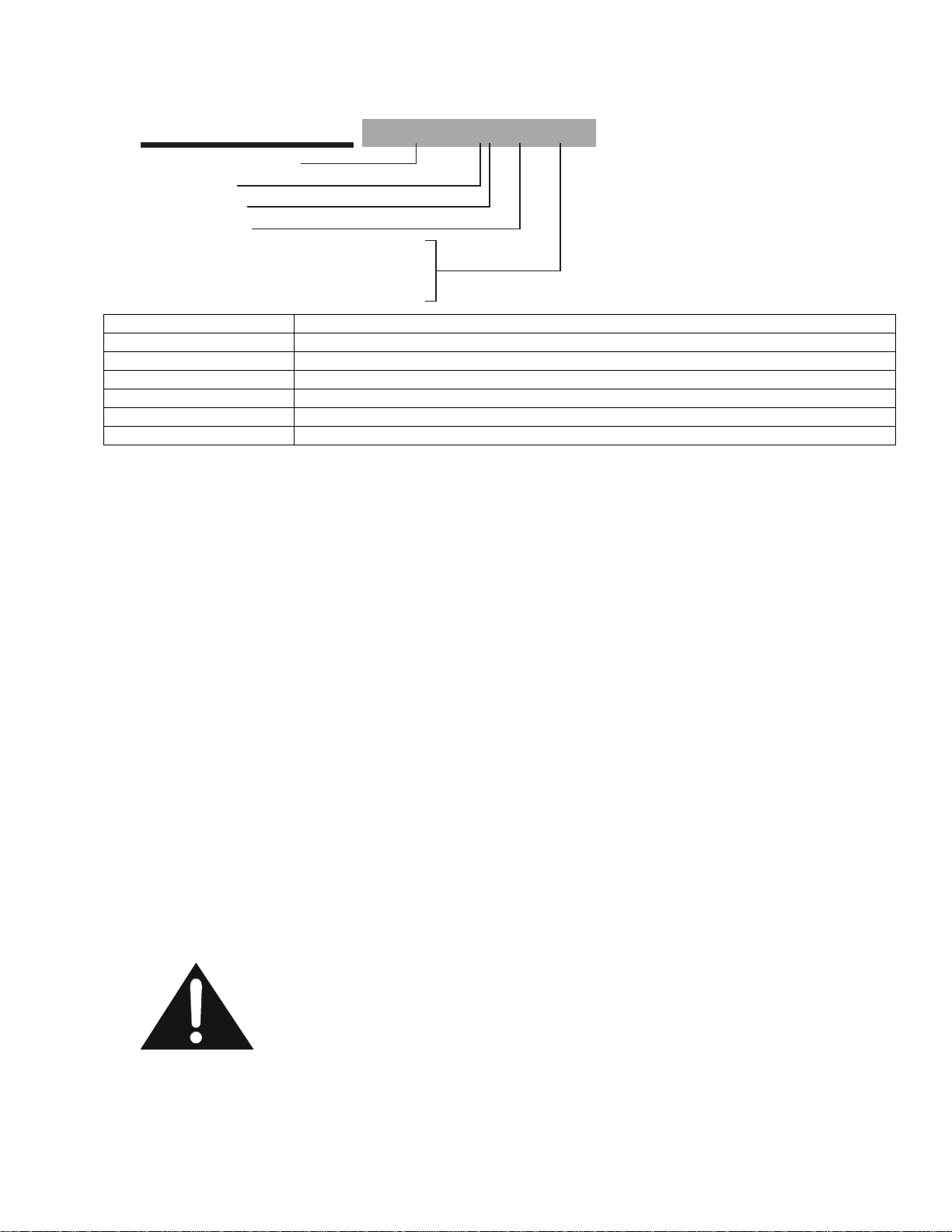
4.12.1 Connecting Power & Commands In Parallel
When multiple NWUPCM-1 power inputs and commands are wired in parallel, all of the
0V terminals must be connected together follows:
Power: Command:
0V-----0V-----0V-----> 0V-----0V-----0V----->
24V---24V---24V----> IN------IN-----IN------>
No crossing of the power input feed or command signal is permitted. If for some reason
the power should become crossed, it will cause a direct short in the system. If properly
fused, the fuse will blow and the NWUPCM-1 will not be damaged. If the command
inputs are wired improperly, damage to the NWUPCM-1 can result.
5. Electrical Specifications
Command Inputs 4-20mA, 0-10V, 0-5V, Pot, PWM
Input Impedance 10K (0-10V), 250(4-20mA), 100K(0-5V)
Control Output SSR Drive, DC pulse, nominally 10V at 15mA
Response Time <50mS
PWM Input Frequency 500Hz-15KHz
PWM Input Level 5 VDC (non isolated) or 24VDC (isolated)
Output Linearity +/-3%
External Potentiometer Res. 10K-25K
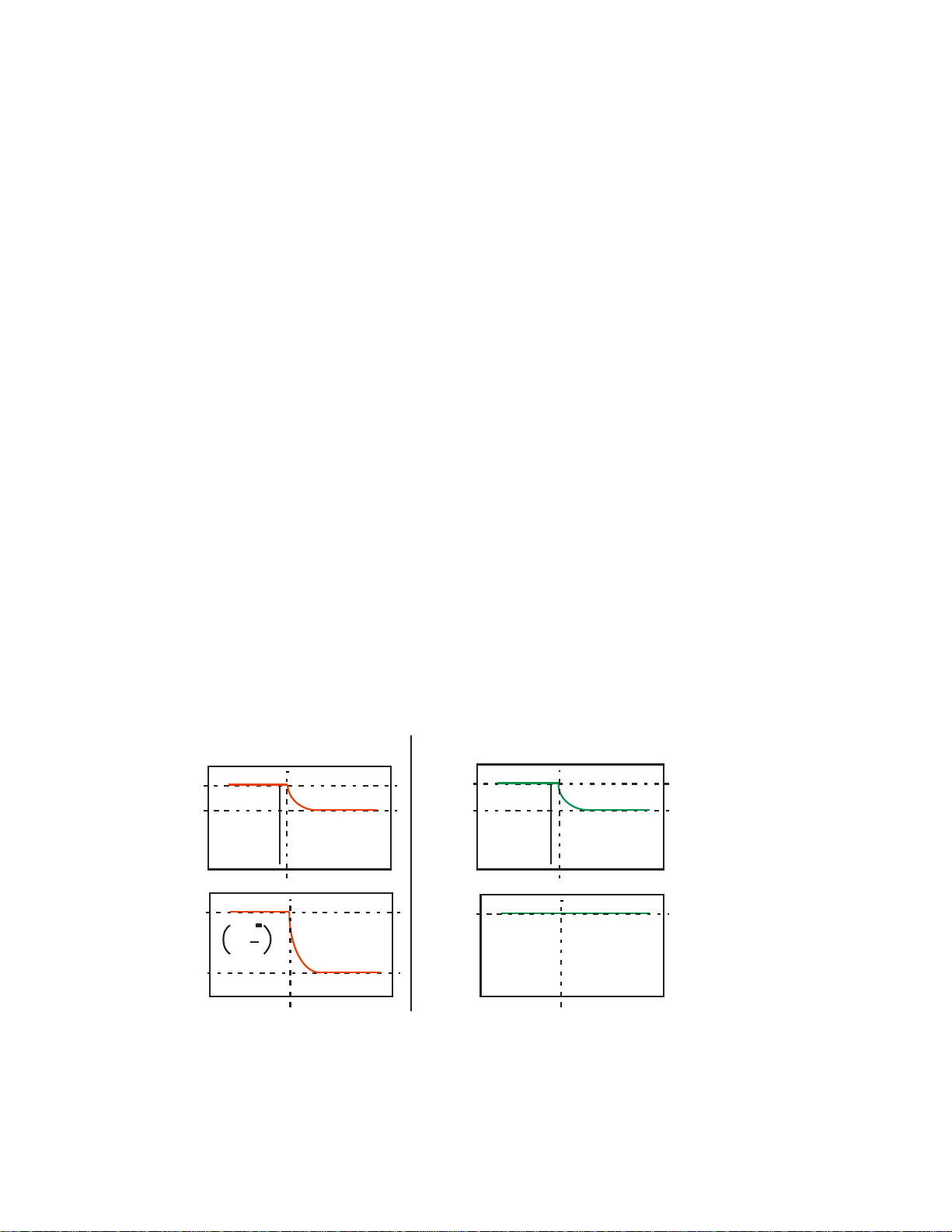
Line Voltage Comp. Range +15%/-15% up to 100% output
Regulation +/-3%
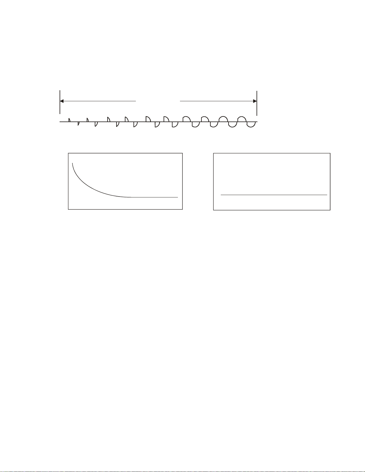
Soft Start Period 5 seconds to reach 100% output
Voltage Limit Range 25-100% of max load voltage.
Ambient Temperature Range 0 to 50 °C
Power Supply 24VAC +10/-10%, <100mA Current Draw.
Line Frequency Range 30 to 90Hz
Line Voltage Range 100-600VAC (External MOV must be installed across
SCRs to limit peak voltages to ~ 850VDC)
SCR Gate Drive Characteristics 16KHz Burst for 1.35mS every half cycle. Initial pulse
peak current of 600mA, maintain pulses, 300mA, 10uS
pulse width per pulse, rise time of 100nS.