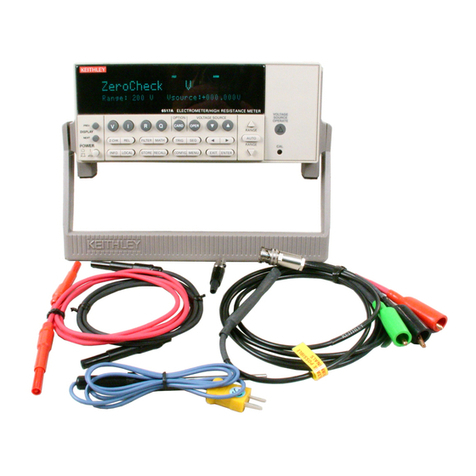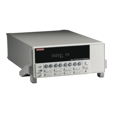
MODELS 61013, 610BR ELECTROMETERS
TABLEOF CONTENTS
Section Page
1. GENERAL DESCRIPTION ........ 1
l-l. General ........... 1
l-2. Features. .......... 1
l-3. Differences Between the Models
6108 and 610BR. ....... 1
l-4. Specifications. ....... 2
l-5. Applications. ........ 3
l-6. Accessories ......... 4
l-7. Equipment Shipped ...... 4
Section ?:I'22
4-6. Calibration Procedures. . . . 31
4-J. Grid Current Check. 33
4-a. DC Amplifier Adjustment 31
4-9. High-Megohm Resistor Veri-
fication. . . 35
4-10. Calibration of Ohms Ranges. 35
4-11. Meter Zero Calibration. . 3j
4-12. Accuracy Check. . . . . . 35
4-13. Drift Check . 36
5. ACCESSORIES . . . . . . 43
2. OPERATION ............. 5
2-1. Front Panel Controls and
Terminals .......... 5
2-2. Rear Panel Controls and
Terminals .......... 6
2-3. Input Connections ...... 6
2~4. Preliminary Procedures. ... 8
2-5. Voltage Measurements ...... 9
2-6. Current Measurements. .... 10
2-7. Resistance Measurements ... 13
2-8. Charge Measurements ..... 15
2-9. Recorder Outputs. ...... 15
Z-10. Unity-Gain Output ...... 17
Z-11. current source. ....... 17
2-12. Static Charge Measurements. . 17
Z-13. Capacitance Measurements. .. 18
2-14. Application Notes ...... 19
5-l. Model 6101A Shielded Test
Lead. . . . . . . . . 43
5-2. Model 61018 Gripping Probe. 43
5-3. Model 6102A Voltage Divider
Probe . . . . . . . . . 43
5-4.. Model 6103A Voltage Divider
Probe . . . . . . . . . 43
5-5. Model 6104 Test Shield. . . 44
5-6. Model 6105 Resistivity
Adapter . . . . . , . . . 44
5-7. Models 2501 and 2503 Static
Detector Heads. . . . . . . . 45
5-8. Model 6106 Electrometer
Connection Kit. . . . . . . . 46
5-9. Model 6107 pH Electrode
Adapter . . . . . . . . . . . 4i
5-10. Model 370 Recorder. . . . . . 48
3. CIRCUIT DESCRIPTION ........ 21
3-l. General ........... 21
3-2. Voltmeter Operation ..... 21
3-3. Voltmeter circuit ...... 22
3-4. Ammeter Operation ...... 24
3-5. Ohmmeter Operation. ..... 24
3-6. Coulombmeter Operation. ... 25
3-7. Power Supply. ........ 26
4. UAINTENANCE ............ 29
4-l. General ........... 29
4-2. Parts Replacement ...... 29
4-3. Troubleshooting ....... 29
4-4. Procedures to Guide Trouble-
shooting. .......... 30
4-5. 234-Volt Ooerarion. ..... 32
6. REPLACEABLE PARTS . . . . . . . 51
6-l. Replaceable Parts List. . . . 51
6-2. How to Order Parts. . . . . . 51
Models 6108, 610BR Replaceable
Parts List. . . . . . . . 52
Model 6108 Schematic Diagram
177953. . . , . . . . . . . 59
Green Repair and
Calibration Forms . . 61
* Change Notice Last Page
* Yellow Change Notice sheet is included
only for instrument modifications affect-
ing the Instruction Xanual.
O268R 1
