03
Field assembly & commissioning
smart slider - Field assembly & commissioning
03. Safety guidelines & procedure
Installation manual
To avoid serious personal injury, all instructions in this manual must be read carefully and followed up.
For questions or topics that are not or not sufficiently described in this manual, please contact the manufacturer or
contact your dealer
General
This manual describes the installation and adjustment of your smart slider system.
Adding or omitting parts can adversely affect the operation and thus the safety of your smart slider system.
Subject to changes.
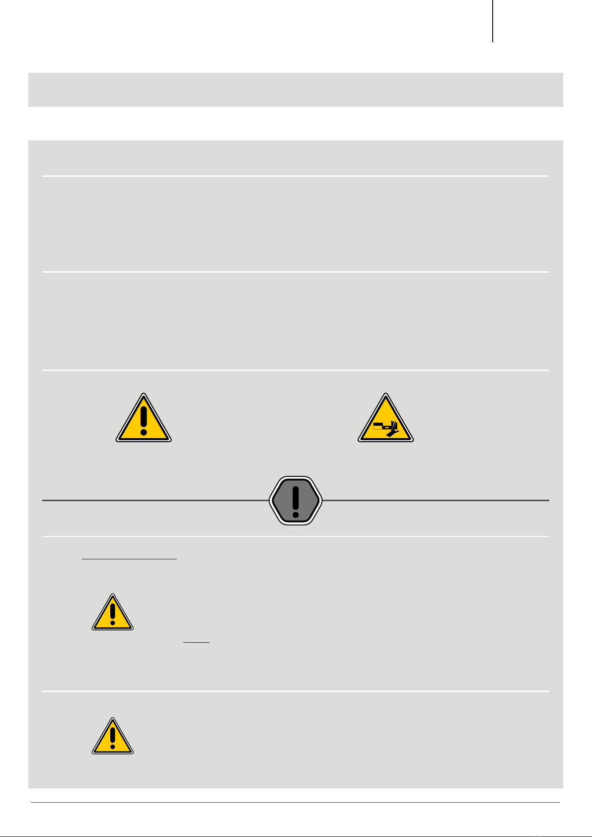
Symbols of warning
- General symbol of danger - Risk of physical pinching
- Symbol of attention
- Read the note very carefully if
this symbol is mentioned.
Procedure
FIRST THINGS FIRST...
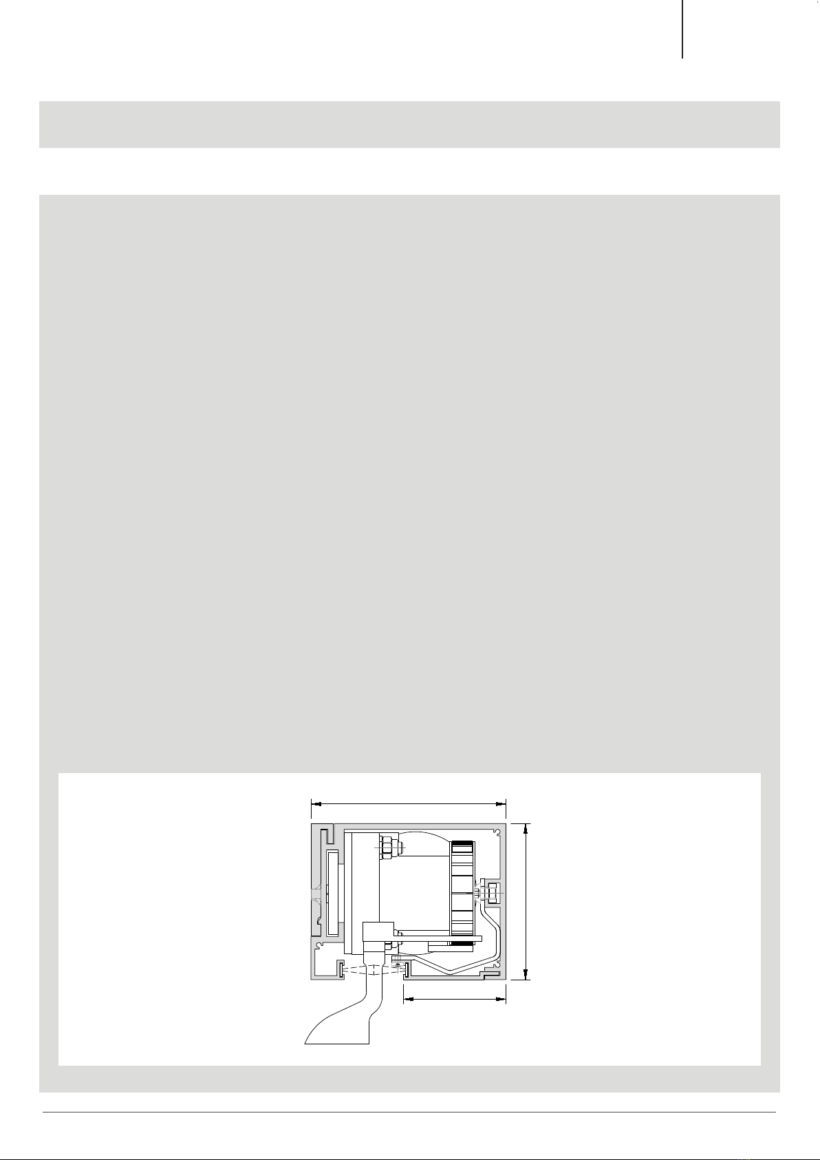
• Mount the drive beam correctly according to the assembly instructions (see page 10/33)
• Couple the window with the flight bar.
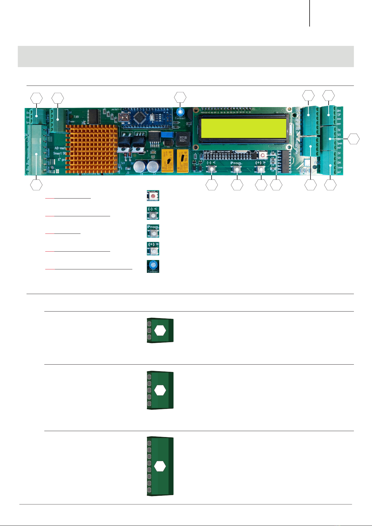
• Insert the powerplug, then an LED will light up under the LCD-display of the control
PCB.
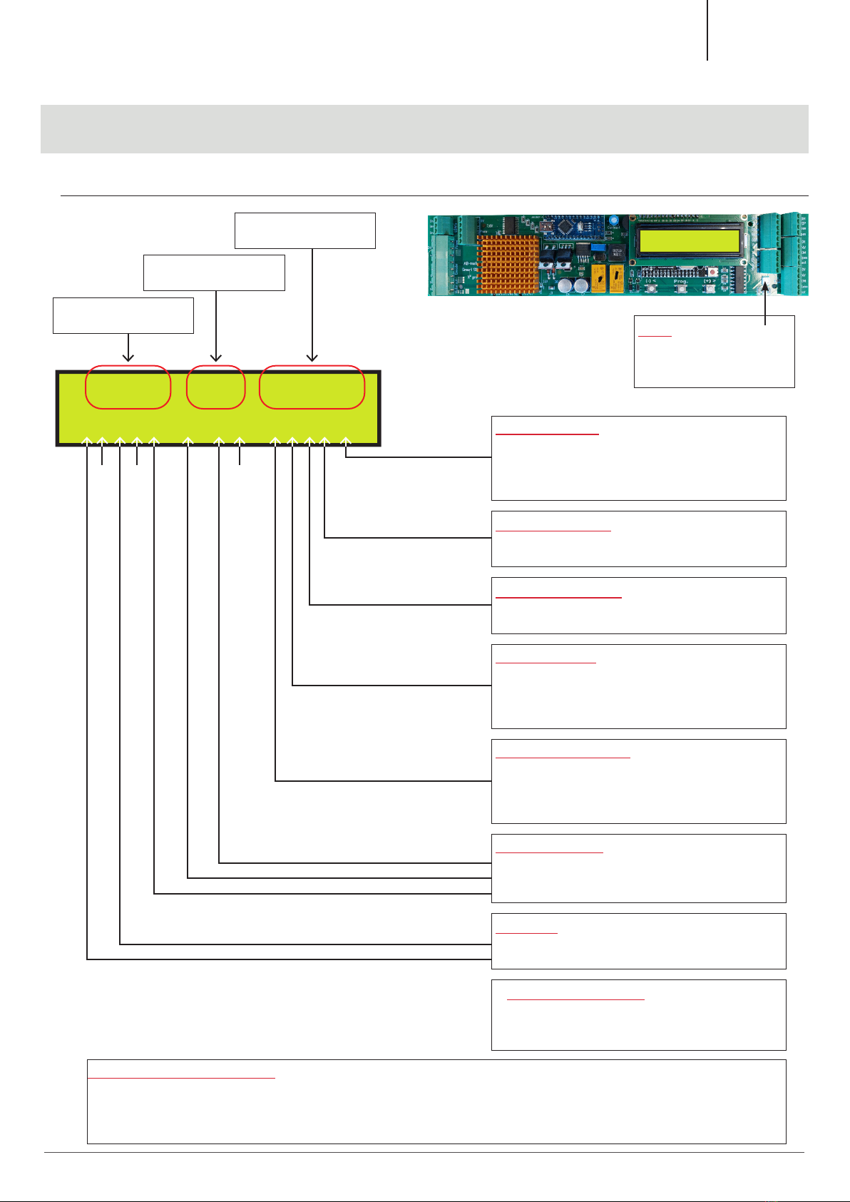
• Now we are ready to complete the basic settings.
• NOTE: All the basic settings are pre-programmed but adjustable to ensure a quick start
Opening movement
• The system must initially know whether the opening movement moves to the right or the
left (seen from the smart slide mounting side)
• Check this on the LCD-display (see page 07/33 “system direction”), this is very crucial in
the rest course of the programming.
6
Keller minimal windows®| 997-00210 | 07-2022
Keller minimal windows®