Kelley HK User manual

User’s Manual
Installation, Operations,
Maintenance and Parts
Part No. 6004754F
Do not install, operate or service this product unless you
have read and understand the Safety Practices, Warnings,
and Installation and Operating Instructions contained in
this User’s Manual. Failure to do so could result in death
or serious injury.
This manual applies to dock
levelers manufactured beginning
October 1, 2008 with the serial
numbers 10251301 and higher.
Hydraulic Dock Leveler
Model HK and HK-S
with Three Button Control

©2009 4Front Engineered Solutions, Inc.
2 6004754F — HK and HK-S Hydraulic Dock Leveler, 3 Button — SafeTFrame™January 2009
Welcome and thank you for choosing this dock leveler from KELLEY®.
This User’s Manual contains information that you need to safely install, operate and maintain the dock leveler. It
also contains a complete parts list and information about ordering replacement parts. Please keep and read this
User’s Manual before using your new dock leveler.
Their use is explained below:
Indicates an imminently hazardous situation which, if
not avoided, will result in death or serious injury.
Indicates a potentially hazardous situation which,
if not avoided, could result in death or serious
injury.
Indicates a potentially hazardous situation which,
if not avoided may result in minor or moderate
injury.
Caution used without the safety alert symbol
indicates a potentially hazardous situation which, if
not avoided, may result in property damage.
This is the safety alert symbol. It is used
to alert you to potential personal injury
hazards. Obey all safety messages that
follow this symbol to avoid possible death or injury.
Introduction.................................................................2
Safety Signal Words...................................................2
Safety Practices..........................................................3
............................................4
................................................5
Installation ..................................................................6
Wiring Diagrams – Standard Control Box.................15
Wiring Diagrams With Optional
................................................20
Operation – With Standard Control Box ...................25
TABLE OF CONTENTS
SAFETY SIGNAL WORDS
Control Box...............................................................28
Preventive Maintenance...........................................31
...................................32
.............................................34
Hydraulic Diagram....................................................38
...................................................39
Parts List...................................................................40
Warranty Information ................................................62
Distributor Information ..............................................64
INTRODUCTION

©2009 4Front Engineered Solutions, Inc.
January 2009 6004754F — HK and HK-S Hydraulic Dock Leveler, 3 Button — SafeTFrame™3
SAFETY PRACTICES
Read these safety practices before installing, operating
or servicing the dock leveler. Failure to follow the safety
practices could result in death or serious injury.
If you do not understand the instructions, ask your supervisor
to explain them to you or call your local Kelley®distributor.
OPERATION
Use restricted to trained operators.
Follow procedures on placard posted near dock leveler.
Do not use this unit to service trailers outside its intended
working range which is 12 inches above and 12 inches below
dock. (18" above and 12" below dock on 10' models)
Do not operate the dock leveler with equipment, material or
people on the ramp or lip.
Do not operate the dock leveler when anyone is in front of it
unless they are securing the maintenance strut.
Stay clear of the dock leveler when it is moving.
Do not
use hands to position dock leveler ramp or lip in vehicle or to
store dock leveler.
Do not use the dock leveler if it looks broken or does not
seem to work right. Tell your supervisor it needs repair right
away.
Do not stand in the driveway between the dock leveler and
a backing vehicle.
Chock vehicle wheels or lock vehicle in place with a
vehicle restraining device and set brakes before loading or
unloading.
Stay clear of leveler unless lip supported by the vehicle bed
or the ramp is supported by both front dock level supports;
unsupported leveler can lower unexpectedly.
Store dock leveler at dock level after below dock end
loading.
Move all equipment, material or people off dock leveler and
store dock leveler at dock level before allowing the vehicle
to pull out.
Do not use a fork truck or other material handling equipment
to lower the ramp.
Before chocking wheels or engaging vehicle restraint, dump
air from air ride suspensions and set parking brakes.
Ensure lip avoids contact with vehicle sides and cargo. If lip
does not lower to vehicle bed, reposition vehicle.
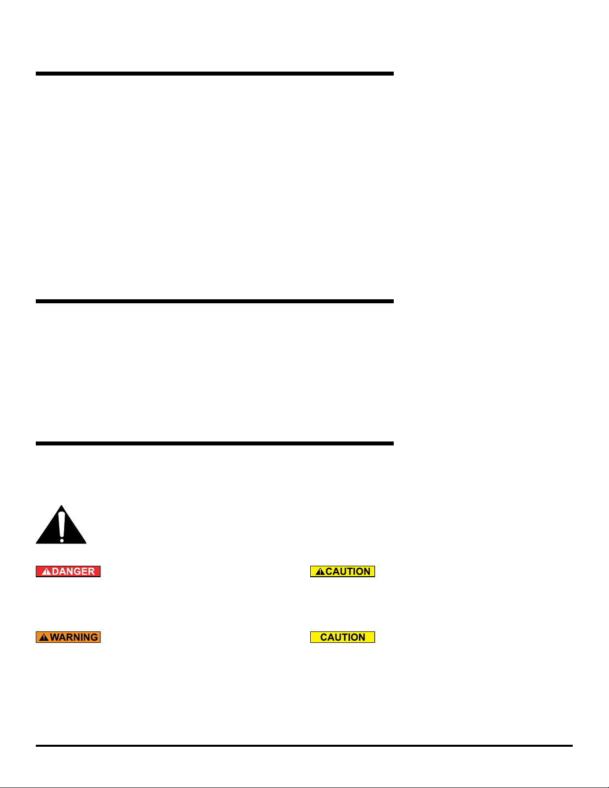
INSTALLATION, MAINTENANCE AND SERVICE
pit and in the driveway in front of the pit while installing,
maintaining or repairing the dock leveler.
Do not operate the dock leveler when anyone is in front of it
unless they are securing the maintenance strut.
maintenance or repair under the dock leveler.
Disconnect the power and properly tag or lock off before
climbing into the dock leveler pit or doing any maintenance
or repair under the dock leveler.
Disconnect the power and properly tag or lock off before
doing any electrical work.
If it is necessary to make troubleshooting checks inside the
box. Touching wires or other parts inside the control box
could result in electrical shock, death or serious injury.
If you have any problems or questions using or operating
the dock leveler, contact your local Kelley distributor for
assistance.

©2009 4Front Engineered Solutions, Inc.
4 6004754F — HK and HK-S Hydraulic Dock Leveler, 3 Button — SafeTFrame™January 2009
OWNER’S RESPONSIBILITIES
The owner’s responsibilities include the following:
The owner should recognize the inherent danger of the
interface between dock and transport vehicle. The owner
should, therefore, train and instruct operators in the safe use
of dock leveling devices.
When a transport vehicle is positioned as closely as
practicable to a dock leveling device, there shall be at least
4" of overlap between the front edge of the lip and the edge
Nameplates, cautions, instructions and posted warnings shall
not be obscured from the view of operating or maintenance
personnel for whom such warnings are intended.
Manufacturer’s recommended periodic maintenance and
inspection procedures in effect at date of shipment shall be
followed, and written records of the performance of these
procedures should be kept.
Dock leveling devices that are structurally damaged or
have experienced a sudden loss of support while under
load, such as might occur when a transport vehicle is pulled
out from under the dock leveling device, shall be removed
from service, inspected by the manufacturer’s authorized
representative, and repaired as needed before being placed
back in service.
The owner shall see that all nameplates, caution and
instruction markings or labels are in place and legible and
that the appropriate operating and maintenance manuals
are provided to users.
shall be made only with written permission of the original
manufacturer.
When industrial vehicles are driven on and off transport
vehicles during the loading and unloading operation, the
brakes on the transport vehicle shall be applied and wheel
chocks or positive restraints that provide the equivalent
protection of wheel chocks engaged.
The dock leveler should never be used outside its vertical
working range or vertical lifting range or outside the
manufacturer’s labeled rated capacity. It must also be
compatible with the loading equipment and other conditions
relating to the dock.

©2009 4Front Engineered Solutions, Inc.
January 2009 6004754F — HK and HK-S Hydraulic Dock Leveler, 3 Button — SafeTFrame™5
RAMP AND LIP GRADES
6'Leveler 8'Leveler 10'Leveler
VEHICLE BED
POSITION
from DOCK,
(in.) RAMP LIP RAMP LIP RAMP LIP
A
B
O
V
E
D
O
C
K
18.0
16.0
14.0
12.0
10.0
8.0
6.0
4.0
2.0
--
--
--
20.5
17.6
14.7
11.9
9.1
6.3
--
--
--
8.0
5.0
2.2
-0.7
-3.5
-6.3
--
--
--
15.3
13.1
11.0
8.9
6.8
4.7
--
--
--
2.7
0.6
-1.6
-3.7
-5.8
-7.9
17.3
15.6
13.9
12.2
10.5
8.8
7.1
5.4
3.8
4.8
3.0
1.3
-0.4
-2.1
-3.8
-5.5
-7.1
-8.8
0.0 3.5 -9.1 2.6 -10.0 2.1 -10.5
B
E
L
O
W
D
O
C
K
-2.0
-4.0
-6.0
-8.0
-10.0
-12.0
0.7
-2.1
-4.9
-7.7
-10.5
-13.3
-11.9
-14.6
-17.4
-20.2
-23.0
-25.9
0.5
-1.6
-3.6
-5.7
-7.8
-9.9
-12.0
-14.1
-16.2
-18.3
-20.4
-22.5
0.4
-1.2
-2.9
-4.6
-6.3
-7.9
-12.1
-13.8
-15.5
-17.1
-18.8
-20.5
RAMP and LIP grades, % for each Dock Leveler length RAMP and LIP grades, % for each Dock Leveler length
6' Leveler 8' Leveler 10' Leveler
VEHICLE BED
POSITION
from DOCK,
(in.) RAMP LIP RAMP LIP RAMP LIP
A
B
O
V
E
D
O
C
K
18.0
16.0
14.0
12.0
10.0
8.0
6.0
4.0
2.0
--
--
--
19.4
16.5
13.7
10.8
8.0
5.2
--
--
--
11.6
8.7
5.8
3.0
0.2
-2.6
--
--
--
14.5
12.3
10.2
8.1
6.0
3.9
--
--
--
6.6
4.5
2.4
0.2
-1.8
-3.9
16.7
15.0
13.2
11.5
9.8
8.2
6.5
4.8
3.1
8.8
7.1
5.4
3.7
2.0
0.3
-1.4
-3.1
-4.7
0.0 2.4 -5.4 1.8 -6.0 1.5 -6.4
B
E
L
O
W
D
O
C
K
-2.0
-4.0
-6.0
-8.0
-10.0
-12.0
-0.3
-3.1
-5.9
-8.7
-11.5
-14.4
-8.2
-11.0
-13.8
-16.6
-19.4
-22.2
-0.3
-2.3
-4.4
-6.5
-8.6
-10.7
-8.1
-10.2
-12.3
-14.4
-16.5
-18.6
-0.2
-1.9
-3.5
-5.2
-6.9
--
-8.1
-9.7
-11.4
-13.1
-14.7
--
4˚ lip bend, 16" lip.
Ramp grade
Lip grade
7˚ lip bend, 16" lip (optional special order)
Fig. 1

©2009 4Front Engineered Solutions, Inc.
6 6004754F — HK and HK-S Hydraulic Dock Leveler, 3 Button — SafeTFrame™January 2009
Push-button
control station
48"
10"
12"-13"
Box located as
shown
Pit
center
line
INSTALLATION
PIT CHECK
1. Check entire dock leveler pit for proper construction
Check to be sure that the pit walls are square and plumb.
be clean and free of any excess debris. Chip excess
be smooth and free of excessive lumps. Check electrical
service running to the pit to assure it agrees with the
correct location and voltage for the junction box. Inspect
the pit and remove all loose trash and construction
debris. Verify the pit matches pit details for your leveler.
See the installation troubleshooting on page 14 if the pit
LEVELER CHECK PRIOR TO INSTALLATION
1. Visually check that the 4 rear hinge pins and retaining
clips are in place.
2. Visually check that the lip shaft collars or shaft retainers
are in place on both lip rods.
3. Verify that both the lip support and the maintenance strut
have safety hitch pins on chains.
4. Visually check that the foot assemblies are in place.
PREPARE SITE
Place barricades around pit on dock oor and drive while
installing, maintaining or repairing dock leveler.
Power to control box must be from fused disconnect
supplied by others. For correct fuse size refer to wiring
diagrams on pages 15-24 of this manual. Before doing any
electrical work, make certain the power is disconnected
and properly tagged or locked off. All electrical work
must be done by a qualied technician and must
meet all applicable codes. If it is necessary to make
troubleshooting checks inside the control box with the
power on, USE EXTREME CAUTION. Do not place ngers
or uninsulated tools inside the control box. Touching
wires or other parts inside the control box could cause
electrical shock, resulting in death or serious injury.
1. The control station, user’s manual and dock bumpers
are attached to the subframe of the dock leveler. The
maintenance strut has a plastic tie wrap holding it to the
subframe, remove these it before placing the leveler into
the pit. Make sure the customer gets the user’s manual
and is properly trained.
2. Mount and wire push-button control station (See Fig.
2) and pit mounted receptacle (See Fig. 3). See wiring
diagram located on the inside cover of the control box or
wiring diagrams on pages 15-24 of this manual for wiring
information. Follow the wiring instructions to set control
connections.
3. If conduit must be installed (replacing an existing
conduit requirements on the pit detail publication 5567
and powered dock leveler wiring diagrams and typical
installation drawings, and powered dock leveler wiring
diagram on page 15-24 for electrical requirements.
Follow all applicable electrical codes and standards.
Fig. 2
Fig. 3

©2009 4Front Engineered Solutions, Inc.
January 2009 6004754F — HK and HK-S Hydraulic Dock Leveler, 3 Button — SafeTFrame™7
INSTALLATION, continued
Before installing the dock leveler, read and follow the
Safety Practices on page 3. Failure to follow the Safety
Practices could result in death or serious injury.
INSTALLATION OF DOCK LEVELER
6' and 8' long levelers using a 19" frame can be converted to
a 24" pit by adding a 4" riser conversion kit Kelley Part No.
6004654. Install the new riser leveling feet. The riser blocks
should be welded to the front frame supports prior to placing
in the pit.
1. Prior to lifting leveler make sure the shipping tie down
bolts seen in Fig. 14 are in place. Install two 3/4”-10UNC
load centering eye bolts into the front and rear of the top
plate and hoist leveler into pit. The dock leveler should
not be lifted in any other manner when place into the pit.
See Fig. 4.
Inadequate lifting equipment or practices can cause a
load to fall unexpectedly. Make sure the lifting chain or
other lifting devices are in good condition and have a
rated capacity of at least 3500 lbs for the lifting angle
used. Never allow anyone to stand on or near the dock
leveler when it is lifted or placed into the pit. Stand clear
of the dock leveler when it is placed into the pit. Failure
to follow this warning can allow the dock leveler to fall,
tip, or swing into people, resulting in death or serious
injury.
Route power cord clear of edges and resting surfaces
so that it is not damaged during lifting and placement.
Plug end may be routed up through the rear hinge until
needed.
INSERTING THE LEVELER INTO THE PIT
2. Position dock leveler in pit about 7" away from the
rear pit wall. Connect cord from motor, and plugs from
switches to junction box at rear pit wall. Place the free
length of cord inside of frame area, free of interference
and wiring diagrams on page 15-24.
Fig. 4
3/4" - 10 UNC
load centering
eyebolt
Fig. 5

©2009 4Front Engineered Solutions, Inc.
8 6004754F — HK and HK-S Hydraulic Dock Leveler, 3 Button — SafeTFrame™January 2009
INSTALLATION, continued
NOTE:
around the leveling feet 1"-6" from the rear wall. Use chisel
to level out area if necessary.
3. Move the dock leveler back to the rear pit curb angle.
See Fig. 6. With the rear leveler angle touching the rear
pit angle, square up the sides of the pit to the sides of
the leveler. The gap should be even on both sides. The
rear frame angle should be within 1/4" on either sides of
the pit curb angle.
NOTE:
The rear frame angle should be about 1/2" lower than the pit
curb angle before leveling. This is normal. See Fig. 7.
LEVELING THE REAR FRAME
4. Using a 1/2" square drive (1/2" ratchet or impact tool)
work from one side to the other, turn each of the leveling
screws on the rear angle, counter clockwise until the top
surface of the rear angle is level with the rear pit curb
rear curb angle. See Fig 8.
The rear edge of the dock leveler should be level or
slightly (1/16" maximum) below dock level.
The top surface of the dock leveler should be level and
a smooth transition with the dock oor curb steel. The
front end should be level and parallel with the rear frame
angle for proper operation. Unequal Shimming of the front
supports may be required to obtain a level front edge.
Turn off all electrical power to the leveler if it has been
previously connected. Welding with dock levelers power
connected can damage the electrical components. A
ground must be attached to the leveler frame. Failure to
do so can result in product damage.
contact with the rear angle. The sides of the leveler
should have a 1/2" gap and parallel with the sides of
the pit. Tack weld the rear angle to rear curb angle in 4
places min 3/8" at the center and at both ends. See Fig.
9 and 10.
NOTE:
Do not weld out the rear angle until after setting the front
supports.
Fig. 6
Fig. 7
1/2"

©2009 4Front Engineered Solutions, Inc.
January 2009 6004754F — HK and HK-S Hydraulic Dock Leveler, 3 Button — SafeTFrame™9
Frame
uprights Rear hinge
assembly
2-1/2"
5"
2-1/2"
5"
5"
5"
2-1/2"
5"
2-1/2"
5"
Bevel groove weld locations
Pit
rear
curb
angle
Rear pit
curb angle
Pit side curb angle
Ramp
Rear
frame
angle
1/2" 1/2"
INSTALLATION, continued
LEVELING THE FRONT FRAME
at the lower end of the hinged lip assembly. See Fig.
14.
Before welding the dock leveler supports to the front
curb angle make sure that the dock leveler support legs
line up with the "V" pocket in the dock leveler support
angle. Move dock levelers support right or left for the
necessary alignment.
7. Tack
weld the front dock leveler supports to the front curb
angle with 3/16" welds as shown in Fig. 12.
8. With the lip pendant insert 24" long 1/2" extensions
between lip and lip rod onto dock leveler support leveling
screw. See Fig. 12. Using a 1/2" drive (1/2" ratchet or
impact tool) turn each leveling screw counter-clockwise
See Fig. 11.
9. Weld the rear frame angle to the rear curb angle using
1/4" bevel joints in the transition plate as your guide. See
Fig. 10.
counter-clockwise to 25-40 ft. lbs.
Fig. 9
Fig. 10
Raises
rear
angle
Leg
adjustment
Fig. 8

©2009 4Front Engineered Solutions, Inc.
10 6004754F — HK and HK-S Hydraulic Dock Leveler, 3 Button — SafeTFrame™January 2009
Cylinder
mounting pad
3/4"
anchor
bolt
(supplied
by others) Stagger and weld
6" x 16" shims
INSTALLATION, continued
hydraulics to position leveler on maintenance strut before
cylinder support riser is in place. Use a suitable lifting
device to place leveler on maintenance strut per step
12 below, then position and weld in the cylinder support
bracket. If electrical power is available, reconnect power
and use the electrical controls to raise the ramp and lip to
their full above dock position. See operating instructions
on front cover of control box. If electrical power in not
available, raise ramp using a chain or other suitable
lifting device.
Hydraulic pressure or mechanical support must be
maintained on the ramp to hold it in the raised position
until the maintenance strut is in place. DO NOT WORK
UNDER THE DOCK LEVELER RAMP OR LIP UNLESS THE
MAINTENANCE STRUT AND LIP LOCK ARE IN PLACE
AND PINNED.
button control station or a suitable lifting device, raise
the deck and secure with maintenance strut.
until the dock leveler reaches its highest position
and hold dock leveler in its highest position.
b. The second person positions the maintenance strut
into the bracket located on the underside of the ramp
assembly and pins it in place with hairpin clip. See
Fig. 15 and the instruction label on maintenance
strut.
c. The second person then locks the lip in extended
position with the lip lock provided on the deck ramp.
Pin the lip lock in place with hairpin clip. See Fig. 15
and instruction label located on the under side of the
dock leveler ramp.
maintenance position.
13. 6x16" shims of the proper thickness are to be placed
under the ramp cylinder mounting pad and welded out
as shown in Fig. 13.
Fig. 12
Flush with floor at this point
Door jamb
Fig. 11
Fig. 13
1/2" sq. drive
adjustment bolt
CCW rotation
to raise
3/16" weld
(both sides)
3/16" weld
3" long (min.)
(both sides)
3/16" weld
(both sides)
3/16" weld
3" long (min.)
(both sides)
3/16" weld
3" long (min.)
3/16" weld
3" long (min.)
3/16" weld
Curb steel
Curb steel

©2009 4Front Engineered Solutions, Inc.
January 2009 6004754F — HK and HK-S Hydraulic Dock Leveler, 3 Button — SafeTFrame™11
Fig. 14
INSTALLATION, continued
Remove
shipping cotter
pins
Manual support of the lip must be maintained until the lip
lock is in place. The lip is free to move downward when
it is released unless the lip lock is pinned in place. DO
NOT WORK UNDER THE DOCK LEVELER RAMP OR LIP
UNLESS THE MAINTENANCE STRUT AND LIP LOCK ARE
IN PLACE AND PINNED.
Welding with the dock levelers power connected can
damage electrical components. If the dock leveler has
been previously connected, turn off power to control
box and unplug all electrical cords from receptacles in
rear pit wall before welding. Failure to do so can result
in product damage.
14. Finish welding both of the adjusted dock leveler supports
in all locations shown in Fig. 12.
if necessary.
Improper installation of anchoring devices or installation
into aged or unsound concrete could result in death or
serious injury.
16. Drill and install 3/4" diameter anchor bolts (min. 3" deep)
in ramp cylinder mounting pad. Weld shims to pad as
noted in Fig 13.
on both sides of dock leveler. See Fig. 16.
lifting hooks from the sides of the ramp.
Instructions on pages 25 through 30 before operating
the dock leveler.
Maintenance
strut bracket
Insert hairpin
clip through
maintenance
strut pin
Maintenance
strut pin
Maintenance
strut
Lip
Ramp Insert
hairpin clip
into lip lock
Lip
lock
Fig. 15
Fig. 16
Shipping tie
down bolt

©2009 4Front Engineered Solutions, Inc.
12 6004754F — HK and HK-S Hydraulic Dock Leveler, 3 Button — SafeTFrame™January 2009
3"
1" Dia.
4"
J bolts (3) per bumper
furnished by Kelley
Company, Inc. locate
and weld to curb
angle at time of
bumper installation.
Molded "L" bumpers
INSTALLATION, continued
Improper installation of anchoring devices or installation
into aged or unsound concrete could result in death or
serious injury.
The dock face must be ush with curb angle to assure
proper bumper mounting.
20. Mount dock bumpers to face of dock. Downhill welds are
unacceptable. See Fig. 17 or 18.
21. Plug or wire in electrical cords and connect power to
dock leveler.
Manually support the lip when storing the lip lock. Stand
clear of the lip when removing support. The lip is free to
move downward when support is removed. Anyone in the
path of the lip when it moves downward can be struck.
Keep your hands, ngers and head away from the lip
when it is released. They could be struck by the lip or
caught between the lip and other parts of the dock leveler
resulting in death or serious injury.
DO NOT REMOVE MAINTENANCE STRUT WITHOUT
HYDRAULIC PRESSURE OR A MECHANICAL LIFTING
DEVICE SUPPORTING RAMP. Raise ramp with
hydraulic pressure or mechanical device before storing
maintenance strut. Stand clear of ramp and lip when
hydraulic pressure or mechanical lift is applied or
removed. Ramp and lip are free to move downward
when support is removed. Removing support without
hydraulic pressure could allow ramp to drop RAPIDLY. If
the dock leveler was raised using a mechanical device,
it should be lowered using the same device.
22. Lift up on the hinged lip and store the lip lock under the
ramp.
23. Two people are needed to store the maintenance strut.
a. One person must push and hold the raise button
until dock leveler reaches its highest position and
hold dock leveler in its highest position.
b. The second person unpins the maintenance strut
from the bracket on the ramp and stores it on the
subframe. See Fig. 15 and the instruction label on
maintenance strut.
Vertical
bumper
mounting
angle
Laminated bumpers
3/8" side of pit
to side of bumper
mounting plate
1/4"
Laminations must be
installed vertically
Full length of bumper
mounting plate.
downhill welds are
unacceptable.
1/4"
To
curb
angle
3/4" dia.
anchor bolt.
field installed.
supplied by
others.
Fig. 17
Fig. 18

©2009 4Front Engineered Solutions, Inc.
January 2009 6004754F — HK and HK-S Hydraulic Dock Leveler, 3 Button — SafeTFrame™13
Warning and operating
instruction placard
OPERATIONS
INSTALLATION, continued
Fig. 19
Cap plug
Rear angle
Fig. 20
c.
The raise button may now be released. The ramp
will lower when the button is released.
24. Permanently mount the laminated dock leveler
wall near the dock leveler control. See Fig. 19. Make
sure the customer gets the user’s manual and is properly
trained.
25. Operate the dock leveler four times through the complete
cycle to check operation. (See Operation section, page
25.)
NOTE:
If you have any problems or questions using or operating
the dock leveler, contact your supervisor or local Kelley®
distributor for assistance.
26. Optional (where applicable), install rear angle cap plugs
(part number 6004488) into adjustment socket holes.
20.

©2009 4Front Engineered Solutions, Inc.
14 6004754F — HK and HK-S Hydraulic Dock Leveler, 3 Button — SafeTFrame™January 2009
PROBLEM POSSIBLE CAUSE SOLUTION
a) Pit is out of square with the sides.
b) One side and rear angle is out of
square.
d) Pit is too deep.
spaced with the rear frame angle
touching the rear curb angle in one
place. Fill the gap between the rear
curb angle and rear frame angle using
shims in weld noted in Fig. 10. See
Fig 20.
edges. The gap on the sides should
be even in the most narrow section
(1/2" Max. per side). See Fig. 22.
c) If large deformations exist in the
out the rough surface using a chisel
or grinder to take out the large
obstructions. The rear leveling legs
can be installed on out of plane
surfaces up to 1/8" at each leg. See
Fig. 23.
d) Weld 4" x 4" shims to the bottom of
the adjustable legs as shown in Fig 4.
INSTALLATION, continued
INSTALLATION TROUBLESHOOTING
The following procedures apply after the leveler is level in
the pit.
Fig. 22
1/8" max
allowable step
no greater than
1" x 3" in size
6"
contact
zone
Fig. 23Fig. 21
Shim and weld flush
Equal
gap
1/2" max.

©2009 4Front Engineered Solutions, Inc.
January 2009 6004754F — HK and HK-S Hydraulic Dock Leveler, 3 Button — SafeTFrame™15
WIRING DIAGRAMS — STANDARD
Before doing any electrical work, make certain the power
is disconnected and properly tagged or locked off. All
electrical work must be done by a qualied technician
and meet all applicable codes. If it is necessary to make
troubleshooting checks inside the control box with
the power on, USE EXTREME CAUTION. Do not place
your ngers or uninsulated tools inside the control box.
Touching wires or other parts inside the control box
could result in electrical shock, death or serious injury.
115/208/230, 1PH, 50/60 Hz

©2009 4Front Engineered Solutions, Inc.
16 6004754F — HK and HK-S Hydraulic Dock Leveler, 3 Button — SafeTFrame™January 2009
WIRING DIAGRAMS — STANDARD, continued
220V, 1PH, 50 Hz

©2009 4Front Engineered Solutions, Inc.
January 2009 6004754F — HK and HK-S Hydraulic Dock Leveler, 3 Button — SafeTFrame™17
WIRING DIAGRAMS — STANDARD, continued
200-480V, 3PH, 50/60 Hz

©2009 4Front Engineered Solutions, Inc.
18 6004754F — HK and HK-S Hydraulic Dock Leveler, 3 Button — SafeTFrame™January 2009
WIRING DIAGRAMS — STANDARD, continued
380V, 3PH, 50 Hz

©2009 4Front Engineered Solutions, Inc.
January 2009 6004754F — HK and HK-S Hydraulic Dock Leveler, 3 Button — SafeTFrame™19
WIRING DIAGRAMS — STANDARD, continued
575V, 3PH, 60 Hz

©2009 4Front Engineered Solutions, Inc.
20 6004754F — HK and HK-S Hydraulic Dock Leveler, 3 Button — SafeTFrame™January 2009
WIRING DIAGRAMS — WITH OPTIONAL A.R.T.D.
115/208/230V, 1PH, 50/60 Hz
This manual suits for next models
1
Table of contents
Other Kelley Lifting System manuals
Popular Lifting System manuals by other brands

Battle-axe
Battle-axe ZF-35-D Operation manual

Challenger Lifts
Challenger Lifts EnviroLift EV1020 Installation, operation & maintenance manual

Vestil
Vestil LM-HP Series quick start guide

Braun
Braun NL Millennium Series Service manual

ASE
ASE 2000 owner's manual

Mohawk
Mohawk V-085-C-X Operation and maintenance manual

Beacon
Beacon BCART-1500D-DC-CTD instruction manual

Dhollandia
Dhollandia DH-AI Series Operation manual

AussieCarHoists
AussieCarHoists YL5000 user manual

Aqua Creek Products
Aqua Creek Products F-714RTC quick start guide

Hi-Force
Hi-Force OM-SLV-01 Series Operating instruction

Vestil
Vestil D-NS-100-LD manual