OPERATING PROCEDURE
1. Unpacking the Lift
Remove the lift from the shipping pallet by
cutting the bands and rocking the lift back
on the 8” transportation wheels. Carefully
roll the lift back off of the pallet onto a
smooth, level surface. Place the lift back
into it’s upright stored position.
The lift has been shipped with the Mast
Hold Down
Strap en-
gaged. The
purpose of
the Mast
Hold Down,
is to keep the
mast sec-
tions from
extending
during transportation. To use your lift, dis-
connect the Safety Latch attached to the
carriage.
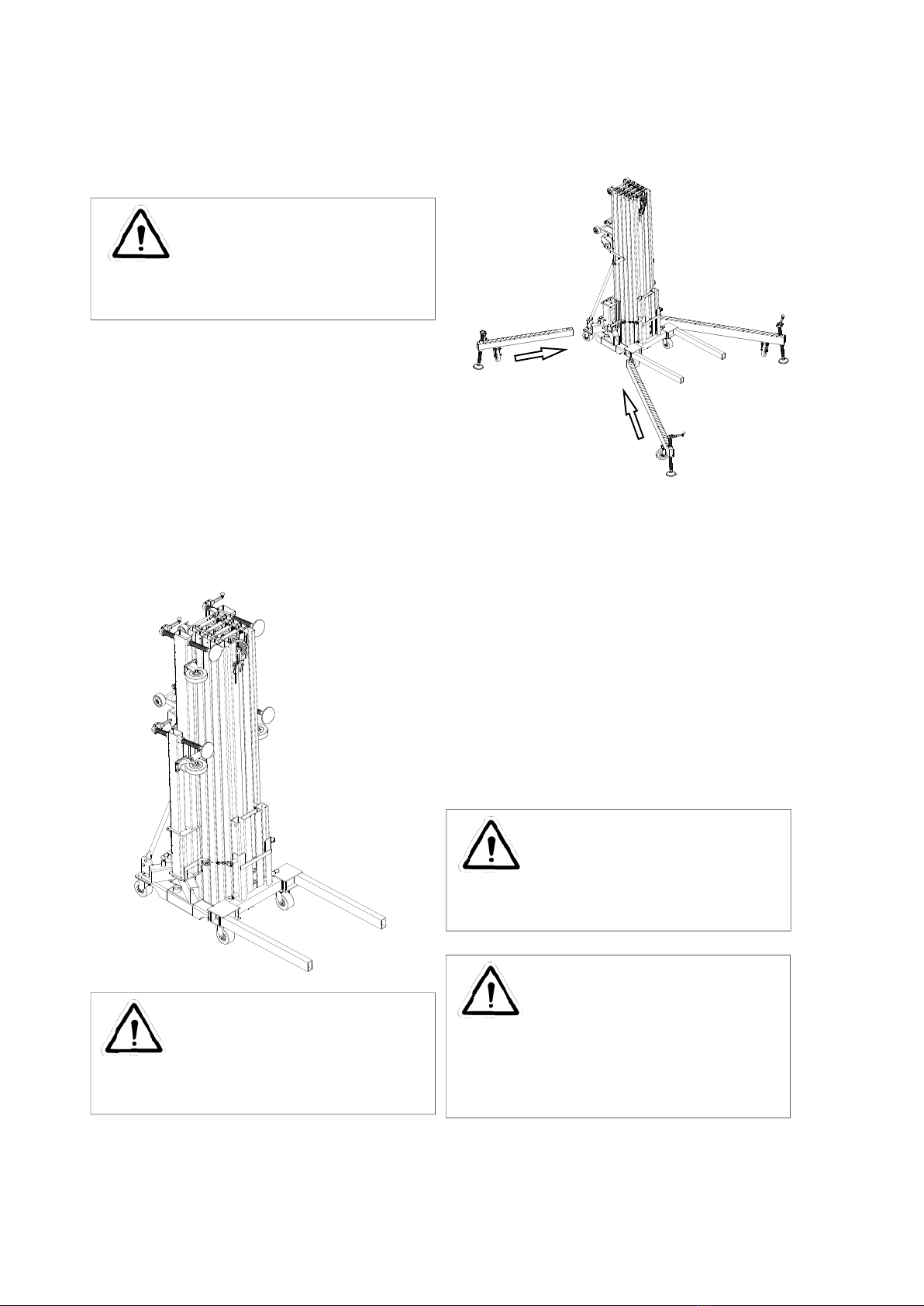
2. Moving Lift to Work Area
(No Load)
The lift is normally moved to the job site by
rolling on its four caster wheels. Note: Do
not pull by the load lifting cable.
IMPORTANT Before tilting unit to reclined
position, the carriage must be in the down
position and the mast hold down strap must
be engaged.
To Tilt the unit into position for transport;
from a squatting position, grasp the legs
just past the front casters and while keep-
ing your back straight, lift upwards to a
standing position while someone supports
the unit from behind. The unit is now ready
to transport.
3. Moving Lift in Work Area
(With Load)
Although it is best to move the unit to the
job site unloaded, light loads may be trans-
ported as long as the stabilizer legs are in-
stalled and the unit is rolled on the eight
caster wheels and on a level surface. Al-
ways have the load in the lowest possible
position before moving the unit.
7
CAUTION
Always use proper lifting techniques.
CAUTION
If a load is being transported,
it should be secured to the fork
to avoid shifting.
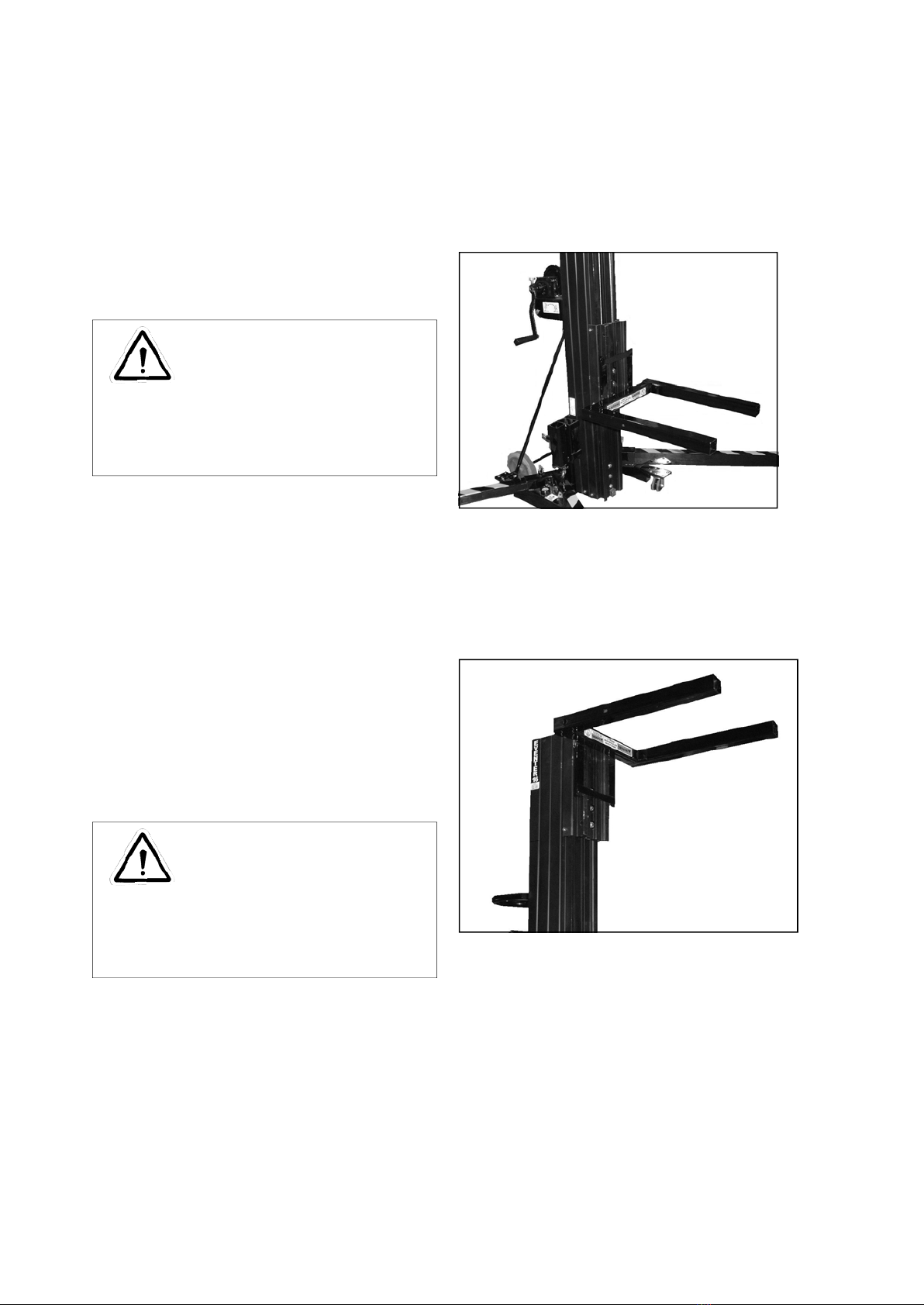
The winch handles
have been placed in
the stored position.
To place the winch
handles in the oper-
ating position, pull up
on the locking pin
and slide the handle
off of the winch
shaft. Rotate the
handle assembly
around so that the
black plastic grip is
facing away from the
winch. While pulling
up on the locking
pin, slide the handle
back on to the winch
shaft. Repeat this
procedure for the
other handle.
When properly in-
stalled, the winch han-
dles should be
mounted 180 degrees
apart, as shown in the
picture. Do not attempt to raise or
lower a load with the handles
mounted in any other manner.