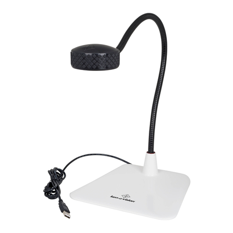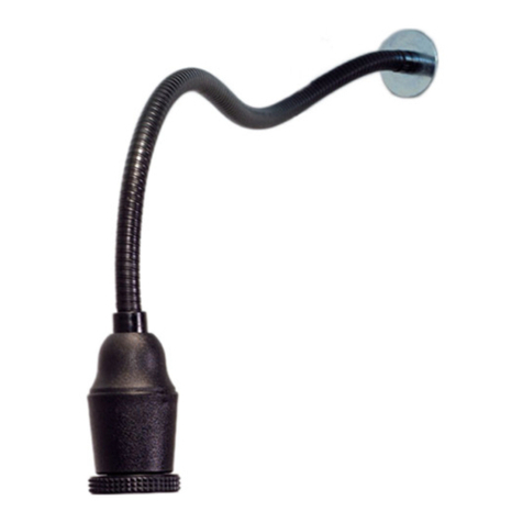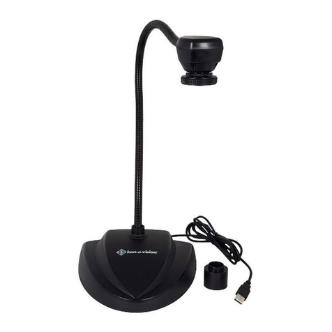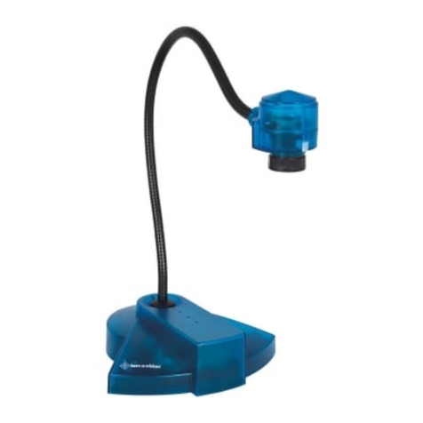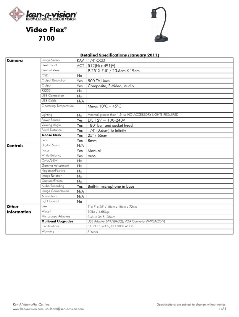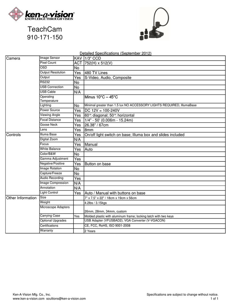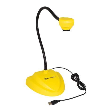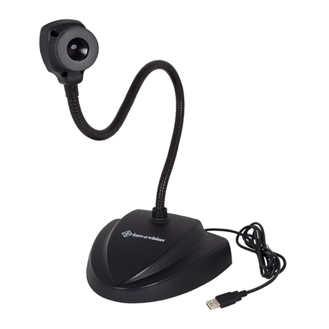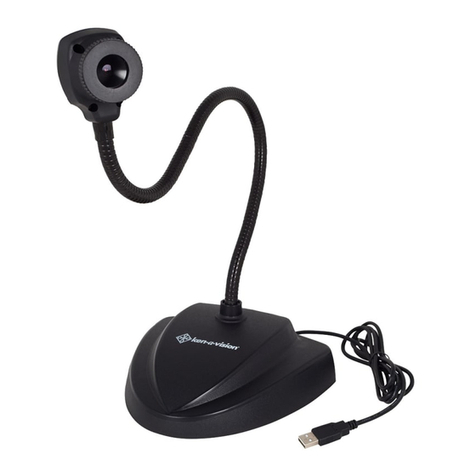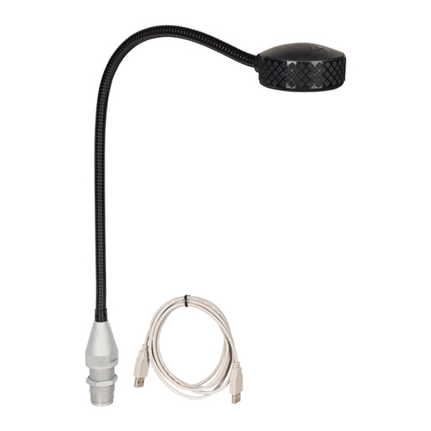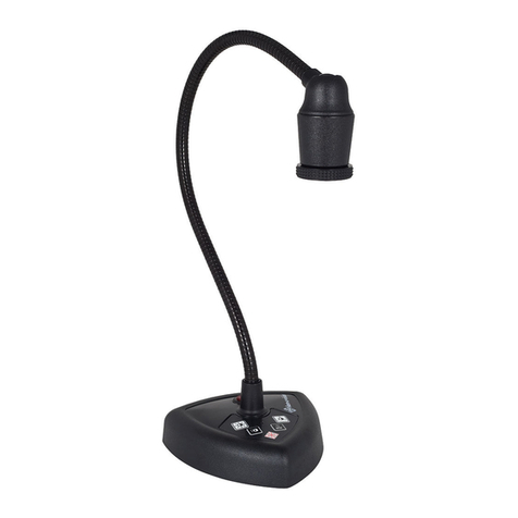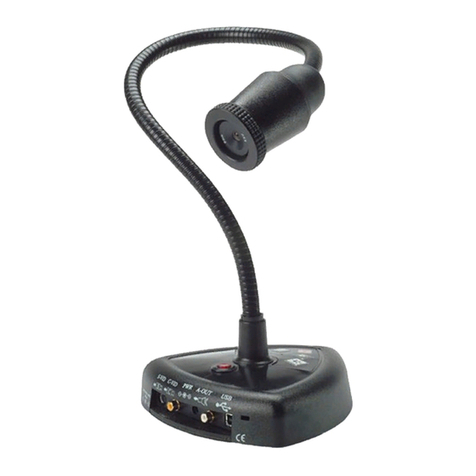
UsingyourVideoImagingDevice
1.RemovetheCamerafromtheshippingcarton.
2. ConnecttheVideoand Powercables.
3. Turn on theOn/OffButton
It’sreadytogo, Noassemblyrequired!
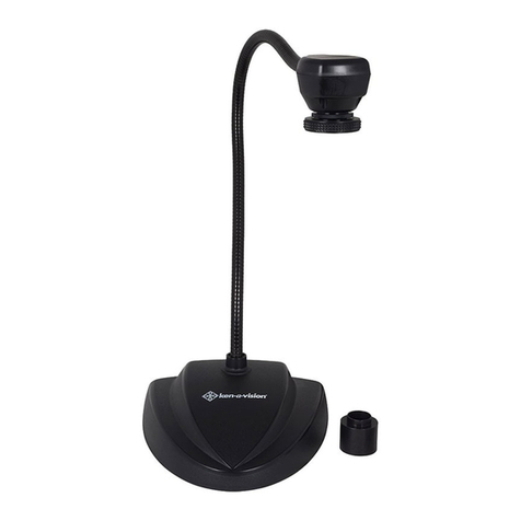
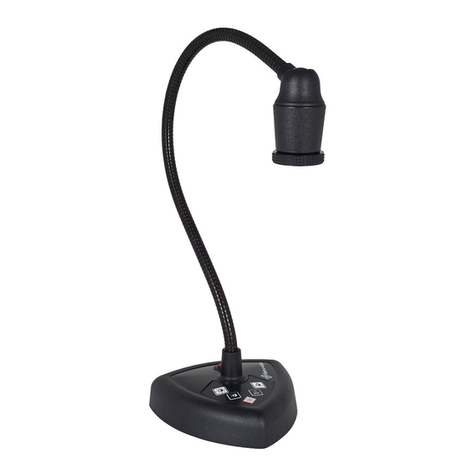
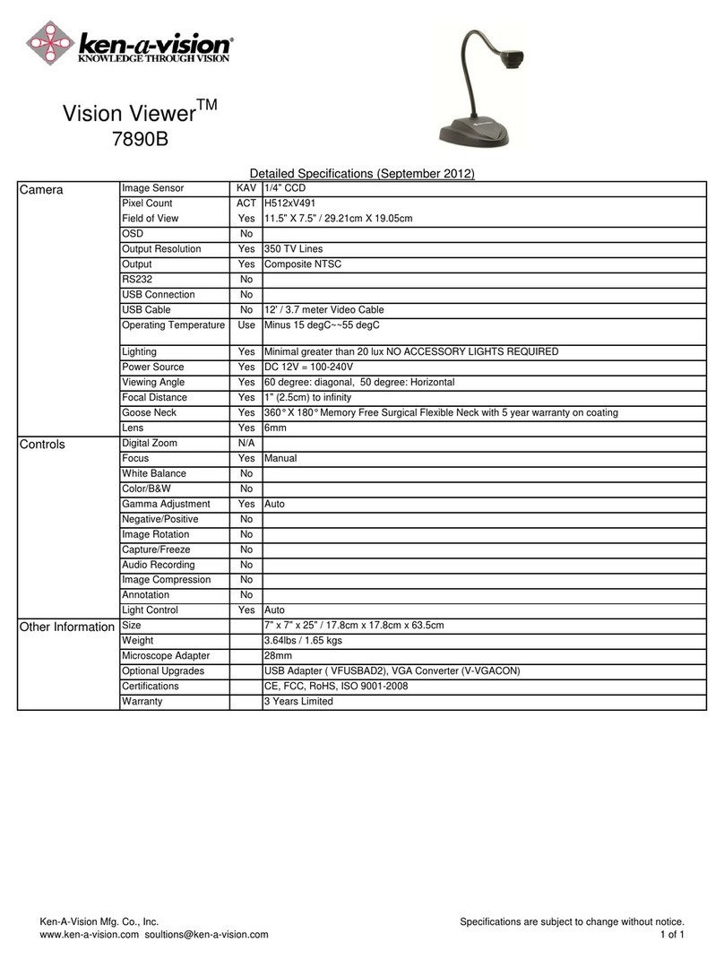
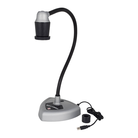
7890B includes: 7890Uincludes:
NTSC/PAL AttachedUSBCable
PowerSupply 28mmEyepieceAdapter
Video/Power CableAttachedCD-ROMSoftware
28mmEyepieceAdapterSoftwareInstructionManual
CONNECTINGTHECABLES:
Connecttheattachedvideocableintothe"VideoIn"connector oftheTV/Monitor,
VCR,orVideoProjector(7890B Model).
NOTE: Consult yourowner'smanualwhen usingany ofthese componentsforoperating
procedurestoaccept avideosignal.
CONNECTINGTHEPOWERSUPPLY:(7890BOnly)
Simplyplugtheendof thepowersupplyintothepowerconnectorlocatedattheend
of theattachedcable.Next,connecttheotherend toa110 or 220 -Voltelectrical
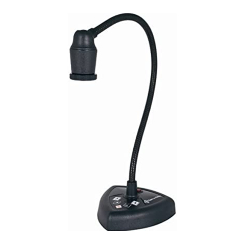
outlet.The"On/Off"buttonislocatedon thebackof your camera,powerisindicat-
edbyanilluminatedREDlightnexttotheon/offbutton.
n
DoNotuse other powersupplies(eveniftheyfit).Theywillproduceimpropervoltageor
reversed polarities. Thiswill seriouslydamage yourCameraand voidyourWarranty.Should
youneed areplacement powersupply, contactKen-A-Vision oryourdealer. Whenusinginter-
nationally,besuretousethecorrect voltage. (110v or220v -powersupply).
CONNECTIONTHEUSBCable:(7890UOnly)
ConnecttheattachedUSBcableintotheUSBportofyour computer.
TV/Monitor ConnectvideocablefromtheCameraintothe“VideoIn”
connectoroftheTV/Monitor. If no“Video-in”isavailable,you mayneedanRF
ModulatororaVCRrecorder.
Seeowner’smanualofTV/Monitorforoperatingprocedures.
VCR (Recorder) ConnectvideocablefromtheCamera(NSSCmodelonly)intothe
“Video-In”connectorontheVCR.ConnectVCRcablesfromyourVCRtoTV.
Seeowner’smanualofVCR foroperatingprocedures.
VideoProjector ConnectvideocablefromtheCameraintothe“Video-In”connectoronthe
videoprojector.
Seeowner’smanualofvideoprojectorforoperatingprocedures.
Computers ToconnecttheCameratoacomputer,thecomputermusthaveaUSBport. Connect
theotherendoftheaffixedUSBcable(7890Umodelonly)totheUSBport inyour
computer.
Seetheowner’smanualofthecomputerfortheoperatingprocedures.
Seethesoftwaremanualforsoftwareinstructions.
FOCUSINGDIRECTIONS:
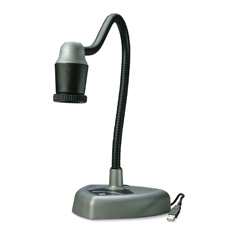
Thefocusing ring locatedon thecameraheadisarubberknurledfocusing system with6mm lens. Simply
turnthefocusing ringuntil youhaveobtainedacrispclearimage.
NOTE:Thelensispermanentlyattachedand mayNOTberemoved.Usecarewhenreachingtheoptimal
focal distance andavoidturning thefocusring toextremeineitherdirection.
CONNECTINGTHE MICROSCOPEEYEPIECE ADAPTER:
TheVision Viewerincludes(1)28mmmicroscopeeyepiece adapterthatallowsyourVisionViewertobe
coupledwithmicroscopesorotherobjectswitheyepieces.The28mm adapterincludedwillfitmost com-
poundmicroscopes.
NOTE:Beforeinstallingthemicroscopeeyepieceadapter,measurethesize oftheoutsidediameterofthe
microscopeeyepiece. (Youmustfirstremovetheeyepiece ifoneisattachedtotheeyepiece).
1.Fullyextendthelens.Gentlyrotatethelenscounter-clock-wiseuntil it isextendedout,formaximum
magnification.
2.Attachthemicroscopeeyepieceadatper.Toinstalltheeyepiece adapter,gentlysliptheadapteroverthe
microscopeeyepiece.
3.AttachtheVisionViewertotheeyepiece adapter.Next,gentlyslidetheVisionViewercameraheadonto
theeyepiece adapter,aligning thegroovearound thelenson thecamerawithedgeoftheeyepiece adapter.
UsingyourVisionViewer7890U
TOLOADTHEUSBSOFTWARE
InsertthesuppliedsoftwareintoyourCDRomdriveand followtheinstructions.
Note:USEONLYGENUINEVISIONVIEWER PARTSANDACCESSORIES.THEYARE MADESPECIFICALLY FOR
THEVISIONVIEWER. FAILUREDUETOUSEOFNON-VISIONVIEWER PARTSWILL VOIDTHE
WARRANTY!
Focusing Ring
PowerIndicator PowerConnector
VideoConnector
On/Off Button
5
3
3
3
