manuals.online logo
Brands
  1. Home
  2. •
  3. Brands
  4. •
  5. Ken A Vision
  6. •
  7. Laboratory Equipment
  8. •
  9. Ken A Vision Video Flex 5400 User manual

Ken A Vision Video Flex 5400 User manual

3. Turn power o , and unplug power supply cord.
4. Then, turn power back on. At this point the same circumstances
should occur as item "2" above.
D. Finish
1. A ter veri y working status o the camera system, plug back in
power supply DC plug. Route all the cables to outside o outer
panel, and then put outer panel back in.
2. It may be okay to leave power supply input plugged to the Fume
Hood AC line system.
Warranty
To activate the ive year limited warranty on your new Video Flex®, either go on line
to www.ken-a-vision.com/warranty.htm or call 816-353-4787 and talk to one o our
customer service representatives.
Technical Support
Having trouble? Visit out support page at
www.ken-a-vision.com/support.htm
Video Flex®Fume Hood
Installation Manual
Part No. 5400
INS-5400.706
/DXPDQ/DQH6XLWH$+LFNVYLOOH1HZ<RUN
7HO)D[
ZZZPLFURVFRSHLQWHUQDWLRQDOFRPLQIR#Q\VFRSHVFRP
1HZ<RUN0LFURVFRSH&RPSDQ\,QF
INSTALLATION
A. Items in the package
1. Video Flex®Camera
2. A black box with 4 Velcro strip attached.
3. ACCESSORIES:
a. 120VAC 60Hz input, 12VDC 500mA output
ower supply.
b. Video Flex USB cable 6 ft (1.8 m).
c. Composite 12 ft video cable (3.66 m).
d. Applied VisionTM Software CD.
e. Ken-A-Vision Capture the Macintosh Solution
Information
B. Installation in to the Fume Hood
1. Remove Right outer panel of the Fume Hood - see
Fume Hood instruction manual how to remove outer
panel on the right side.
2. Locate a pre drilled ½" hole on the side panel on right
side of the Fume Hood.
3. Insert flat metal washer in the bottom of Video Flex
neck.
4. Insert bottom portion of Video Flex neck (threaded
portion) into pre-drilled ½" hole. The Video Flex head
must be inside of Fume Hood. Then, insert star
washer into threaded neck on outside of the panel.
5. Insert a pipe nut, and tight. Be sure to position Video
Flex®camera eye in the forward direction before
tighten a pipe nut.
6. Camera cable inside of Video Flex neck should come out
approximately 7 - 8 inches from the end of threaded area
of flex neck.
7. Locate optimum position to mount black box. Should
consider camera cable length reached enough. Ideal
location is the Left-above from the camera cable exit.
8. Detach pre-attached two Velcro strips from the black
box. eel-off white backing paper and attach into the
place pre-located. Then place black box on top of the
Velcro on the panel and press evenly for secure
mounting.
C. Testing
1. rior to testing, please lug in the following items into the
black box:
a. lug in video cable and the other end to the
monitor.
b. lug in USB cable and the other end to the
computer USB jack.
c. lug in camera cable into male connector on the
black box.
d. lug in 12 v DC power supply into DC power jack.
2. ress power switch on. At this point the following should
occur;
a. ower button should lit.
b. Round Red LED should lit.
c. Video image should show on the monitor and
should be able to focus by adjust focusing knob.
d. The same video image should show on the
computer monitor (if you have installed ken-a-vision
software in your computer).

Other Ken A Vision Laboratory Equipment manuals

Ken A Vision T-1922 User manual

Ken A Vision

Ken A Vision T-1922 User manual

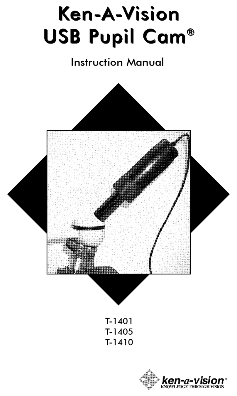
Ken A Vision T-1401 User manual

Ken A Vision

Ken A Vision T-1401 User manual

Popular Laboratory Equipment manuals by other brands

Waters ACQUITY UPLC Overview and maintenance guide

Waters

Waters ACQUITY UPLC Overview and maintenance guide

Heathrow Scientific eCOUNT instruction manual

Heathrow Scientific

Heathrow Scientific eCOUNT instruction manual

Dectris EIGER2 X 500K user manual

Dectris

Dectris EIGER2 X 500K user manual

Medic Therapeutics MT-MINIUVWAND-001 manual

Medic Therapeutics

Medic Therapeutics MT-MINIUVWAND-001 manual

Scientifica LBM-7 manual

Scientifica

Scientifica LBM-7 manual

Helmer UltraCW II Operation manual

Helmer

Helmer UltraCW II Operation manual

DLab D3024 user manual

DLab

DLab D3024 user manual

Gilson ASPEC GX-271 user guide

Gilson

Gilson ASPEC GX-271 user guide

Miele PG 8593 operating instructions

Miele

Miele PG 8593 operating instructions

Yamato DF410 instruction manual

Yamato

Yamato DF410 instruction manual

Hach BODTrak Instrument manual

Hach

Hach BODTrak Instrument manual

Malvern Nano Series Quick Start & Self Installation Guide

Malvern

Malvern Nano Series Quick Start & Self Installation Guide

Alere DDS 2 user guide

Alere

Alere DDS 2 user guide

Himedia COLONY COUNTER LA660 quick start guide

Himedia

Himedia COLONY COUNTER LA660 quick start guide

BioLAB BLVR-202 Operation manual

BioLAB

BioLAB BLVR-202 Operation manual

Pasco Scientific WA-9612 Instruction manual and experiment guide

Pasco Scientific

Pasco Scientific WA-9612 Instruction manual and experiment guide

Thermo Scientific SL40 instruction manual

Thermo Scientific

Thermo Scientific SL40 instruction manual

USA Lab RE-501 manual

USA Lab

USA Lab RE-501 manual

manuals.online logo
manuals.online logoBrands
  • About & Mission
  • Contact us
  • Privacy Policy
  • Terms and Conditions

Copyright 2025 Manuals.Online. All Rights Reserved.