kenall MEDMASTER ENVELA MRSDL4L Series User manual

www.kenall.com |P: 800-4-Kenall |F: 262-891-9701 |10200 55th Street Kenosha, Wisconsin 53144, USA
This product complies with the Buy American Act: manufactured in the United State swith more than 50% of the component cost of US origin It may be covered by patents
found at www.kenall.com/patents.Content of specication sheets is subject to change; please consult www.kenall.com for current product details. ©2019 Kenall Mfg.Co.
1
INSTALLATION INSTRUCTIONS
F-4826-090418
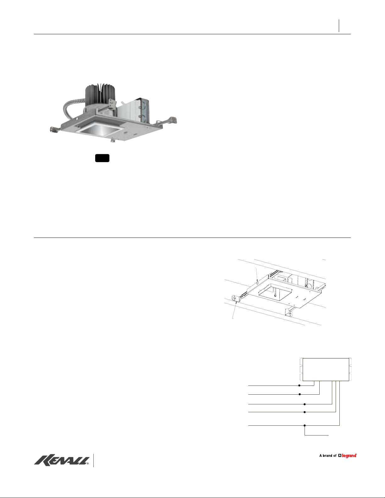
MRSDL4L / M2SRDL4L SERIES
MEDMASTER ENVELA® REGRESSED DOWNLIGHT
NEW CONSTRUCTION- DRYWALL CEILING – RECOMMENDED CEILING CUTOUT- 4.125" SQUARE
FIGURE 1
Patient Room & Surgical Suite Luminaires
THE ENVELA DOWNLIGHT CONTAINS SENSITIVE ELECTRONICS. TAKE CARE TO AVOID DAMAGE BY IMPROPER HANDLING OR STATIC
ELECTRICITY DISCHARGE (ESD). EITHER TYPE OF DAMAGE COULD RENDER THE SYSTEM INOPERABLE OR CAUSE LATENT FAILURE.
LED
Note- 28L or 28T xtures must be installed minimum
24" center to center, 12" from wall and have 1/2"
clearance above the trim.
1. Loosen locking screws to extend hanger bars. See
Figure 1.
2. Align bottom of hanger bar tabs to bottom of joist.
3. Secure luminaire hanger bars using nails or screws.
4. Position luminaire as required and lock position by
tightening locking screws.
5. Remove junction box cover.
6. Remove appropriate 1/2" knockout(s) and connect
to electrical service.
7. Wire per wiring diagram using approved wire
connectors. See Figure 2.
8. Replace junction box cover.
LOCKING SCREW
ALIGN TO BOTTOM OF JOIST
COPPER GROUND WIRE
LED
DRIVER
GREEN
CONNECT GROUND WIRE TO GREEN
AND COPPER GROUND WIRES
WHITE
CONNECT COMMON SUPPLY WIRE TO WHITE WIRE
BLACK
CONNECT HOT SUPPLY WIRE (120-277V) TO BLACK WIRE
GREY
CONNECT (-)10V FROM DIMMER TO GREY WIRE (OPT)
VIOLET
CONNECT (+)10V FROM DIMMER TO VIOLET WIRE (OPT)
FIGURE 2
IMPORTANT SAFEGUARDS
When using electrical equipment, basic safety precautions
should always be followed, including the following:
THIS PRODUCT MUST BE INSTALLED IN ACCORDANCE
WITH THE APPLICABLE INSTALLATION CODE BY A PERSON
FAMILIAR WITH THE CONSTRUCTION AND OPERATION OF
THE PRODUCT AND THE HAZARDS INVOLVED.
CE PRODUIT DOIT ÊTRE INSTALLÉ SELON LE CODE
D’INSTALLATION PERTINENT, PAR UNE PERSONNE QUI
CONNAÎT BIEN LE PRODUIT ET SON FONCTIONNEMENT
AINSI QUE LES RISQUES INHÉRENTS.
DISCONNECT POWER TO ALL CIRCUITS BEFORE WIRING FIXTURE.
INSTALL IN ACCORDANCE WITH ALL NATIONAL, STATE, AND
LOCAL CODES. DO NOT CONNECT TO AN UNGROUNDED
SUPPLY. READ ALL FIXTURE MARKINGS AND LABELS TO
ENSURE CORRECT INSTALLATION OF FIXTURE. SUPPLEMENTAL
INSTRUCTIONS MAY BE LOCATED ON THE FIXTURE, IN ADDITION
TO THIS INSTRUCTION SHEET, REGARDING ORIENTATION, OR
MOUNTING RESTRICTIONS.
SAVE THESE INSTRUCTIONS

www.kenall.com |P: 800-4-Kenall |F: 262-891-9701 |10200 55th Street Kenosha, Wisconsin 53144, USA
This product complies with the Buy American Act: manufactured in the United State swith more than 50% of the component cost of US origin It may be covered by patents
found at www.kenall.com/patents.Content of specication sheets is subject to change; please consult www.kenall.com for current product details. ©2019 Kenall Mfg.Co.
2
INSTALLATION INSTRUCTIONS
F-4826-090418
FIGURE 3
FIGURE 4
GRID CEILING – RECOMMENDED CEILING CUTOUT- 4.125" × 4.125” SQUARE OPENING
1. Loosen locking screws to extend hanger bars.
See Figure 3.
2. Position luminaire as required and lock position by
tightening locking screws.
3. Attach luminaire securely to grid using brackets,
screws and nuts provided or wiring to grid members.
See Figure 4
4. Remove junction box cover.
5. Remove appropriate 1/2" knockout(s) and connect
to electrical service.
6. Wire per wiring diagram using approved wire
connectors. See Figure 2.
7. Replace junction box cover.
TRIM CONNECTION AND INSTALLATION
To clean reector use only a soft micro ber lens cloth
or alcohol wipe.
1. With nished ceiling or tile in place, loosen
adjustment screws (see Figure 5) and position ring
even with ceiling. Re-tighten screws securely.
2. Connect electrical plugs and fasten conduit adapter
to trim housing using the screw provided
(see Figure 6).
3. Install trim into ceiling opening with retention
springs aligned to slots in the adjustment ring.
Compressing springs as necessary. Press rmly
to ceiling.
4. Check to ensure the gasket between the trim ring
and ceiling is compressed.
TRIM REMOVAL
1. To remove trim, pull rmly on ange.
LOCKING SCREW
LOOSEN SCREWS
POSITION RING
EVEN WITH CEILING
FIGURE 5

www.kenall.com |P: 800-4-Kenall |F: 262-891-9701 |10200 55th Street Kenosha, Wisconsin 53144, USA
This product complies with the Buy American Act: manufactured in the United State swith more than 50% of the component cost of US origin It may be covered by patents
found at www.kenall.com/patents.Content of specication sheets is subject to change; please consult www.kenall.com for current product details. ©2019 Kenall Mfg.Co.
3
INSTALLATION INSTRUCTIONS
F-4826-090418
FIGURE 6
SERVICE
CAUTION- BEFORE BEGINNING ANY SERVICE,
DISCONNECT POWER TO THE FIXTURE.
DRIVER REPLACEMENT
1. For room side access, remove trim from ceiling by
pulling downward rmly on the ange.
2. Disconnect conduit adapter by loosening the screw.
(See Figure 6)
3. Disconnect connector and remove trim housing to a
safe location.
4. Remove (4) screws and remove adjustment ring.
5. Lift spring to remove LED driver/cover assembly.
6. Disconnect leads and reconnect to new driver. Refer
to Figure 2 for wiring diagram.
7. Install new driver/cover. Place cover tab into slot in
frame and pivot until snapped under spring.
8. Re-install adjustment ring and adjust ush to ceiling.
9. Re-install trim housing following instructions in
“Trim Connection and Installation” section.
MODULE REPLACEMENT
1. For room side access, remove trim from ceiling by
pulling downward rmly on the ange.
2. Disconnect conduit adapter by loosening the screw.
(See Figure 6)
3. Disconnect connector and remove trim housing to a
safe location.
4. Remove heatsink from lower housing by removing
(3) screws and lifting off.
5. Remove (3) screws, reector plate and insulators
as shown in Figure 7. LED module may then be
removed and replaced.
6. Apply heatsink paste to back of new module.
7. Feed the connector through the opening in the
housing and position the insulators and reector
plate.
8. Secure the LED module, insulators and reector
plate to the housing by re-installing the (3) screws.
See Figure 7.
9. Re-assemble the heatsink to the lower housing by
replacing the (3) screws.
10. Re-install trim housing following instructions in
"Trim Connection and Installation" section.
FIGURE 7

www.kenall.com |P: 800-4-Kenall |F: 262-891-9701 |10200 55th Street Kenosha, Wisconsin 53144, USA
This product complies with the Buy American Act: manufactured in the United State swith more than 50% of the component cost of US origin It may be covered by patents
found at www.kenall.com/patents.Content of specication sheets is subject to change; please consult www.kenall.com for current product details. ©2019 Kenall Mfg.Co.
4
INSTALLATION INSTRUCTIONS
F-4826-090418
For technical assistance, call 1-800-4KENALL (1-800-453-6255).
WARRANTY
CUSTOMER SERVICE
For warranty information visit www.kenall.com/Resources/Certied-Performance-Warranties
This manual suits for next models
1
Table of contents