Kenmore 405.35016510 User manual

Use & Care Guide
Manual de Uso y Cuidado
English/Español
Kenmore®
16"/18" Wall Fan
3 Speeds, Oscillation Switch , Safety Metal Guard
16"/18" Ventilador De Pared
3 Velocidades, Oscilación Interruptor, SeguridadMetálica Rejilla
Model/Modelo: 405.35016510/405.35018510
Customer Assistance /Asistencia al Cliente
1-866-646-4332
Sears Brands Management Corporation
Hoffman Estates, IL 60179 U.S.A.
www.kenmore.com
www.sears.com
www.kmart.com
®

CAUTION
Read and follow all instructions before operating fan. Do not use fan if any part
are damaged or missing.
WARNING
1. This appliance is not intended for use by young children or infirm persons
without supervision.
2. Young children should be supervised to ensure that they do not play with the
appliance.
3. This appliance has a polarized plug (one blade is wider than the other). To
reduce the risk of electrical shock, this plug is intended to fit in a polarized
outlet only one way. If the plug does not fit fully into the outlet, reverse the
plug. If the plug still does not fit, contact a qualified electrician. Do not
attempt to bypass this safety feature.
4. If the supply cord is damaged ,it must be replaced by manufacturer or its
service agent or a similarly qualified person in order to avoid a hazard.
5. To reduce the risk of fire or electrical shock, do no use this fan with any solid
state speed control device.
6. Changes or modifications to this unit not expressly approved by the party
responsible for compliance could void the user’s authority to operate the
equipment.
RULES FOR SAFE OPERATION
1. Never insert fingers, pencils, or any other object through the housing when the
fan is running.
2. Disconnect fan when moving from one location to another.
3. Disconnect fan when removing grilles for cleaning.
4. Do not leave the fan running unattended.
5. Be sure the fan is on a stable, flat surface when in operation.
6. The rules about cords and plugs are as follows:
(1) This product uses overload protection (fuse). A blown fuse indicates an
overload or short-circuit situation. If the fuse burns out, unplug the
product from the outlet. Replace the fuse as per the user servicing
instructions (follow product marking for proper fuse rating) and check
the products.If the replacement fuse blows, a short-circuit may be present
and the product should be discarded or call Customer Assistance at
1-866-646-4332 to arrange for possible repair.
(2) Do not operate any fan with a damaged cord or plug. Discard fan or call
Customer Assistance at 1-866-646-4332 to arrange for possible repair.
(3) Do not run cord under carpeting. Do not cover cord with throw rugs,
runners, or similar coverings. Do not route cord under furniture or
appliances. Arrange cord away from traffic area and where it will
not be tripped over.
1
READ AND SAVE THESE INSTRUCTIONS

Blade Set
PART NAMES
GUARD & FAN BLADE ASSEMBLY
1. Unscrew and remove the spinner clockwise (or obtain
from parts bag), and the plastic nut counterclockwise
(Fig. 2). You may have to hold the shaft in place with
one hand to unscrew the spinner with the other. Mount
the rear guard against the motor face so that the pin
at the motor face bottom fits through the tear drop
hole in the rear guard mounting ring. When correctly mounted the set of two
tabs on each side of the motor face will also fit through their designated holes
in the mounting ring, and the rear guard will rest flat and evenly on the motor
face. Screw the plastic nut back onto the motor face to secure the rear
guard in place. Fig. 1
2. Mount the blade set onto the motor shaft through the center hole in the blade
set. Insert the retaining pin on the motor shaft into the slots in the Blade set
core. Turn the spinner counterclockwise onto the shaft to tighten the blade set
into place. Fig. 3
3. Open the five latch clips on the rear guard. Align the logo on the front guard
so that it will read horizontally. Insert the edge of the front guard into the
fixed clip at the bottom of the rear guard. Use the five latch clips to secure the
two guards together. Fig. 4
2
INSTALLATION
The fan must be installed into a wall stud or into a stable
wooden upright standing vertically from the floor.
CAUTION: To prevent the fan from falling down, be sure
to install it into a wall stud. Do not install it only into a
wall surface not backed with a stud.
Fig.2 Fig.3 Fig.4
Fig.1
Hardware
kit
3 Screws
Wall
mounting
bracket
Retaining
Nut

3
The fan requires little maintenance. Do not try to fix it by yourself. Refer it to
qualified service personnel if service is needed,or call Customer Assistance at
866-646-4332.
1. Before cleaning fan, always unplug it from the electrical outlet.
2. To ensure adequate air circulation to the motor, use a vacuum to keep vents
at the rear of the motor housing free from dust, fluff, etc. Do not disassemble
fan to remove dust or fluff.
CAUTION: To avoid injury from electrical shock, unplug the fan before using a
vacuum cleaner to clean the vents.
3. Wipe the exterior parts with a soft cloth soaking a mild detergent.
Do not use any abrasive detergent or solvents to avoid scratching the surface.
Do not use gasoline or paint thinner as a cleaner.
4. Do not allow water or any other liquid into the motor housing or interior parts.
MAINTENANCE INSTRUCTIONS
FUSE REPLACEMENT
1. Grasp the plug and remove it from the receptacle or other outlet device.
Do not unplug by pulling on the cord.
Installing the stand
Mount the stand on the bracket by inserting the
bracket catch into the slot on the stand.
Fix the stand to the bracket with the retaining nut.
NOTE: If the retaining nut does not pass through the
hole in the bracket, push the stand downwards until
it is fully mounted onto the bracket.
SPEED ADJUSTMENT
Adjust to the desired speed by pulling switch cord (A).
The control dial will click to a different position with
each pull of the cord.
Off---Off Low---Low Med---Medium High---High
OSCILLATION CONTROL
Pull switch cord B to start and stop fan oscillation.
To adjust vertical air direction, lightly push on the front
guard to tilt either up or down.
Installing the mounting bracket
Fix the supplied mounting bracket firmly to the wall
using the three screws.
NOTE: The bracket should be positioned at least
14 inches from the ceiling and at least 12 inches
from adjoining wall.
IMPORTANT: Make sure the Mounting Bracket is
installed into a wall stud. Otherwise, use wall
anchors to provide proper support.
Speed Adjustment
Oscillation Control
Wall stud

2. Open the fuse cover. Slide open the fuse access
cover on top of power plug towards blades.
3. Remove the fuse carefully. Push the fuse from the
other side or turn the fuse holder over to remove the fuse.
WARNING: Risk of fire. Replace the fuse only with 2.5 A, 125
Volt fuse.
4. Close the fuse cover. Slide closed the fuse access cover on top of the
power plug.
WARNING: Risk of fire. Do not replace power plug. It contains a safety
device (fuse) that should not be removed. Discard product if the power plug
is damaged.
NOTICE:
1. After replacing fuse, do not at first operate at full speed. Doing so may cause
product malfunction or damage.
2. If the fan doesn't seem to operate properly after fuse replacement, check to
make sure that the fuse was inserted correctly.
CLEANING
1. Be sure to unplug fan from the electrical supply source before cleaning.
2. Clean plastic fan parts with a cloth or sponge moistened in a solution of mild
soap and water. Thoroughly remove soap film with a damp cloth. Wait for
surfaces to completely dry before running fan.
3. Be sure not to allow water or other liquid to enter the inside of the motor.
PRINTED IN CHINA
4

5
PRECAUCIÓN
Lea y siga todas las instrucciones antes de operar el ventilador. No lo utilice si
alguna pieza está dañada o pérdida.
ADVERTENCIA
1. Este aparato no está diseñado para uso por los niños pequeños o personas
enfermas sin supervisión.
2. Los niños pequeños deben ser supervisados para asegurarse de que no
jueguen con el aparato.
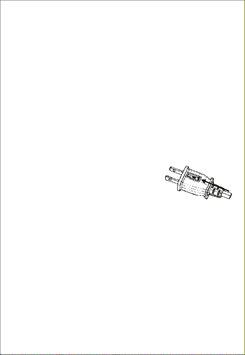
3. Este aparato cuenta con un enchufe polarizado (una pala más ancha que la
otra). Para reducir el riesgo de descargas eléctricas, este enchufe está
diseñado para encaje en un tomacorriente polarizado en una sola dirección.
Si el enchufe no se encaja plenamente en el tomacorriente, invierta el enchufe.
Si todavía no se encaja, contacte con un electricista calificado. No intente
omitir esta función de seguridad.
4. Si el cable de alimentación está dañado, debe ser reemplazado por el
fabricante o su agente de servicio o una persona calificada de modo
semejante, para evitar peligros.
5. Para reducir el riesgo de incendios o descargas eléctricas, no utilice este
ventilador con ningún aparato de control de velocidad de estado sólido.
6. Los cambios o modificaciones a esta unidad no expresamente aprobados
por la parte responsable de la conformidad podrían invalidar la autoridad
del usuario para operar el equipo.
LEA Y GUARDE ESTAS INSTRUCCIONES
REGLAS SOBRE LA SEGURIDAD DE OPERACIÓN
1. Nunca inserte los dedos, lápices, o cualquier otro objeto a través de la carcasa
cuando el ventilador está en funcionamiento.
2. Desconecte el ventilador al moverlo de un lugar a otro.
3. Desconecte el ventilador al retirar las rejillas para la limpieza.
4. No deje el ventilador en funcionamiento sin atención.
5. Asegúrese de que el ventilador se encuentre en una superficie estable y llana
cuando está en funcionamiento.
6. Las reglas sobre cables y enchufes se muestran abajo:
(1) Este producto adopta la protección (fusible) contra sobrecarga. Un fusible
fundido indica una situación de sobrecarga o cortocircuito. Si se quema el
fusible, desenchufe el producto desde el tomacorriente. Reemplace el
fusible según las instrucciones de mantenimiento para el usuario (siga lo
marcado en el producto para la especificación del fusible adecuada), y
verifique el producto. Si se funde el fusible, podría aparecer un
cortocircuito y debe descartar el producto o llamar al Servicio de Atención
al Cliente al 1-866-646-4332 para hacer arreglos para la posible
reparación.

6
(2) No opere ningún ventilador con un cable o enchufe dañado. Descarte el
ventilador o llame al Servicio de Atención al Cliente al 1-866-646-4332
para hacer arreglos para la posible reparación.
(3) No haga funcionar el cable bajo la alfombra. No cubra el cable con
alfombrillas, tapetes, o cubiertas similares. No tienda el cable bajo los
muebles o aparatos. Disponga el cable alejado del área de tránsito y donde
no se tropezará.

Motor Guarda trasera Conjunto
de pala
Cono de
rectificación Guarda frontal
Tuerca de plástico
NOMBRES DE PIEZAS
MONTAJE DE LA PALA Y REJILLA
1. Desatornille y retire el cono de rectificación a derecha
(u obténgalo desde la bolsa de piezas) y la tuerca de
plástico a izquierda (Figura 2). Debería sostener el eje
en su lugar con una mano para desatornillar el cono de
rectificación con la otra mano. Monte la guarda trasera
contra la superficie del motor, para que el pasador en
la parte inferior de la superficie del motor se encaje a través del orificio de
gota en el anillo de montaje de la guarda trasera. Una vez correctamente
montado el conjunto de dos lengüetas en cada lado de la superficie del motor,
también se encajará a través de sus orificios designados en el anillo de
montaje, y la guarda trasera reposará de forma plana y lisa sobre la
superficie del motor. Vuelva a atornillar la tuerca de plástico en la superficie
del motor, para sujetar la guarda trasera en su lugar. Figura 1
2. Monte el Conjunto de pala en el eje del motor a través del orificio central
ubicado en el conjunto de Pala. Inserte el pasador de retención ubicado en el
eje del motor en las ranuras ubicadas en el núcleo del Conjunto de pala.
Inserte el cono de rectificación en la punta del eje y gírelo a izquierda para
sujetar el Conjunto de pala en su lugar. Figura 3
3. Abra los tres clips de cierre en la guarda trasera. Alinee el logotipo en la
guarda frontal, para que será leído de forma horizontal. Inserte el borde de
la guarda frontal en el clip fijado a la parte inferior de la guarda trasera.
Utilice los tres clips de cierre para sujetar las das guardas juntas. Figura 4
7
Fig.2 Fig.3 Fig.4
Fig.1
Cono de
rectificación
Cono de
rectificación
Apretar
Apretar
Clip
Conjunto de pala
Pasador de
retención
Ranura
Tuerca de plástico
Aflojar
kit de
hardware
3 Tornillos
Soporte
de pared
Tuerca de
Retención

Instalación del Pedestal
Monte el pedestal en el soporte insertando la garra del
soporte en la ranura ubicada en el pedestal.
Fije el pedestal al soporte con la tuerca de retención.
NOTA: Si la tuerca de retención no pasa a través del
orificio ubicado en el soporte, empuje el pedestal
hacia abajo hasta que esté montado plenamente en
el soporte.
AJUSTE DE VELOCIDAD
Ajuste a la velocidad deseada tirando el cable del
interruptor (A). La perilla de control se encajará en
una posición diferente con cada tirada del cable.
Off---Apagado Low---Baja Med---Media High---Alta
OSCILLATION CONTROL
Tire el cable del interruptor B para activar o desactivar
la oscilación del ventilador.
Para ajustar la dirección del aire vertical, empuje la
guarda frontal ligeramente para inclinar a arriba o
abajo.
Instalación del Soporte de Montaje
Fije el soporte de montaje provisto apretadamente a la
pared utilizando tres tornillos.
NOTA: El soporte debe ser localizado al menos 14
pulgadas desde el techo y al menos 12 pulgadas desde
la pared unida.
IMPORTANTE: Asegúrese de que el Soporte de Montaje
esté instalado en un poste de pared. De lo contrario,
utilice las anclas de pared para proporcionar un soporte
adecuado.
Speed Adjustment
Oscillation Control
8
INSTALACIÓN
El ventilador debe ser instalado en un poste de pared
o un pedestal erguido de madera estable verticalmente
desde el suelo.
PRECAUCIÓN: Para evitar la caída del ventilador,
asegúrese de instalarlo en un poste de pared. No lo
instale en una superficie de pared, solamente, sin apoyo
de un poste.
Techo
Pared
(A) Ajuste de velocidad
(B) Control de oscilación
Poste de
pared
Ranura en el
lado trasero
Ranura en el
lado trasero
Soporte
de montaje
Soporte
de montaje
Tuerca de
retención
Tuerca de
retención
Pedestal
Pedestal

9
REEMPLAZO DEL FUSIBLE
1. Tome el enchufe y retírelo desde el tomacorriente u
otro aparato de salida. No lo desenchufe tirando el
cable.
2. Abra la cubierta de fusibles. Deslice para abrir la cubierta
de acceso a fusibles en la parte superior del enchufe hacia las palas.
3. Retire el fusible cuidadosamente. Empuje el fusible desde el otro lado o dé
vuelta el portafusibles para retirar el fusible.
ADVERTENCIA: Riesgo de incendios. Reemplace con el fusible de 2.5A, 125
Voltios, solamente.
4. Cierre la cubierta de fusibles. Deslice para cerrar la cubierta de acceso a
fusibles en la parte superior del enchufe eléctrico.
ADVERTENCIA: Riesgo de incendios. No reemplace el enchufe eléctrico. Ésto
contiene un aparato de seguridad (fusible) que no se debe retirar. Descarte el
producto si el enchufe eléctrico está dañado.
El ventilador requiere poco mantenimiento. No intente repararlo por sí mismo.
Consulte al personal de reparación calificado si es necesaria la reparación, o
llame al Servicio de Atención al Cliente al 866-646-4332.
1. Antes de limpiar el ventilador, siempre desenchúfelo desde el tomacorriente
eléctrico.
2. Para garantizar una circulación de aire adecuada para el motor, utilice una
aspiradora para proteger los conductos de ventilación en la parte trasera de
la carcasa del motor contra el polvo, pelusa, etc. No desmonte el ventilador
para eliminar el polvo o pelusa.
PRECAUCIÓN: Para evitar lesiones debido a las descargas eléctricas,
desenchufe el ventilador antes de utilizar una aspiradora para limpiar los
conductos de ventilación.
3. Limpie las partes exteriores con un paño suave humedecido en un detergente
no agresivo.
No utilice ningún detergente abrasivo o disolvente para evitar la rascadura
superficial.
No utilice ninguna gasolina o diluyente de pintura como limpiador.
4. No se permite que el agua o cualquier otro líquido entre en la carcasa del
motor o piezas interiores.
INSTRUCCIONES DE MANTENIMIENTO
AVISO:
1. Tras reemplazar el fusible, no opere al comienzo a plena velocidad. Si lo
hace, podría causar el mal funcionamiento o daños al producto.
2. Si parece que el ventilador no funciona adecuadamente tras el reemplazo
del fusible, verifique para asegurarse de que se inserte el fusible
correctamente.

IMPRESO EN CHINA
10
LIMPIEZA
1. Asegúrese de desenchufar el ventilador desde la fuente de alimentación
eléctrica antes de la limpieza.
2. Limpie las piezas de plástico del ventilador con un paño o esponja
humedecido en una solución jabonosa no agresiva y agua. Elimine la
película de jabón por completo con un paño mojado. Espere a que se
sequen las superficies plenamente antes de operar el ventilador.
3. Asegúrese de no permitir que el agua o cualquier otro líquido entre en la
parte interior del motor.

KENMORE LIMITED WARRANTY
FOR ONE YEAR from the date of sale this appliance is warranted against defects in material or
workmanship when it is correctly assembled, operated and maintained according to all supplied
instructions.
WITH PROOF OF SALE, a defective appliance will be replaced free of charge. For warranty
coverage details to obtain free replacement, visit the web page: www. kenmore. com/ warranty
This warranty is void if this appliance is ever used for other than private household purposes.
This warranty gives you specific legal rights, and you may also have other rights which vary from
state to state.
Sears Brands Management Corporation, Hoffman Estates, IL 60179
®
GARANTÍA LIMITADA DE KENMORE
DURANTE UN AÑO a partir de la fecha de venta de este aparato se garantiza contra defectos de
materiales o mano de obra en la premisa de montaje, operación, y mantenimiento adecuados según
todas las instrucciones provistas.
CON EL COMPROBANTE DE VENTA, un aparato defectuoso se reemplazará sin gastos algunos. Para
obtener más detalles sobre la cobertura de la garantía para el reemplazo gratuito, visite la página
web: www.kenmore.com/ warranty. Esta garantía es inválida si este aparato se ha utilizado para
otras finalidades que no sean el propósito doméstico privado. Esta garantía le concede los derecho
legales específicos, y usted también podría tener otros derechos que varían de estado a estado.
Sears Brands Management Corporation, Hoffman Estates, IL 60179
This manual suits for next models
1
Table of contents
Languages:
Other Kenmore Fan manuals

Kenmore
Kenmore 405.35162510 User manual

Kenmore
Kenmore 258.32002310 User manual

Kenmore
Kenmore 405.35182510 User manual

Kenmore
Kenmore 405.34036310 User manual

Kenmore
Kenmore 405.35090510 User manual

Kenmore
Kenmore 405.34030310 User manual

Kenmore
Kenmore 27.32600310 User manual

Kenmore
Kenmore 405.35040510 User manual

Kenmore
Kenmore 127. 32217310 User manual

Kenmore
Kenmore ELITE 233.59966400 Installation guide