manuals.online logo
Brands
  1. Home
  2. •
  3. Brands
  4. •
  5. Kenmore
  6. •
  7. Range
  8. •
  9. Kenmore 79070112705 Firmware update

Kenmore 79070112705 Firmware update

INSTALLATION AND SERVICE MUST BE PERFORMED BY
A QUALIFIED INSTALLER.
IMPORTANT: SAVE FOR LOCAL ELECTRICAL INSPECTOR'S USE.
READ AND SAVE THESE INSTRUCTIONS FOR FUTURE REFERENCE.
This conversion kit must be installed by a qualified service technician in accordance with the
manufacturer's instructions and all applicable codes and requirements ofthe authority having jurisdiction. Failure
to follow instructions may result in fire, explosion or production of carbon monoxide causing property damage,
personal injury or loss of life. The qualified service agency is responsible for the proper installation ofthis kit. The
installation is not proper and complete until the operation ofthe converted appliance is checked as specified in the
manufacturer's instructions supplied with this kit.
Before proceeding with the conversion, shut offthe gas supply before disconnecting electrical power
to the range. Be sure both power supplies are off before installing the conversion kit. Failure to do so could cause
serious bodily injury.
Choose the combination of top burners that are featured on your range to
determine the parts that are included in your kit.
Note: When burners are converted from Natural to LP the BTU rating is as
follows:
5,000 BTU* Natural Gas to 4,500 BTU* LP Gas
9,500 BTU* Natural Gas to 8,000 BTU* LP Gas
12,000 BTU* Natural Gas to 10,000 BTU* LP Gas
14,200 BTU* Natural Gas to 11,000 BTU* LP Gas
Surface Burner Orifice marked 0.68mm 4,500 BTU* (blue)
Surface Burner Orifice marked 0.89mm 8,000 BTU* (no color)
Surface Burner Orifice marked 0.95mm 10,000 BTU* (green)
Surface Burner Orifice marked 1.01mm 11,000 BTU* (red)
Installation Instructions
m
_ i/
.o:3 __
-= == ' :E
316237907 0 1 0
316237906 3 2 4
316237905 1 1 0
316237904 0 0 0
316248100 1 1 1
A
m
1
1
1
1
1
,.O
o
m,,_ _
.i
1
2
0
1
1
*Note: For operation at elevations above 2000 ft., appliance rating
shall be reduced at the rate of 4 percent for each 1000 ft. above sea
level.
NOTE: After replacing the natural gas to Lp orifices, be sure to
keep the original factory installed natural gas orifices for future
range conversion back to natural gas.
How to Convert the Range for use with LP/
Propane Gas
1. Convert the Pressure Regulator
To access the gas regulator, remove the storage drawer or warmer
drawer. If equipped with a storage drawer, open and remove the drawer
completely. For models equipped with warmer drawer, follow the
instructions below to remove warmer drawer.
a. _!_ Electrical Shock Hazard can occur and result in
serious injury or death. Disconnect electrical power to the range
before removing the warmer drawer for servicing.
b. Locate glide lever on each side of drawer, pull up on the left glide lever
and push down on the right glide lever (See Figure 1).
c. Pull the drawer away from the range (See Figure 2).
d. Remove the regulator access cover if equipped. Do not remove
thePressure Regulator or allow it to turn.
e. Remove the dust protector from the cap. Using a 5/8" wrench,
unscrew the cap from the pressure regulator. Do not remove the
spring from the regulator.
f. Turn the cap over so the hollow end faces outward. Place the solid
end of the cap into the loop end of the dust protector (See Figure 3).
g. Replace the cap on the regulator. The letters LP should be visible on
the exposed end of the cap. Snap the dust protector over the
regulator cap.
Tools Required:
3/8", 1/2" and 5/8" Open End Wrench
1/8" Wide Flat Blade Screwdriver
7mm Nutdriver
Pull up with finger
Left Glide
Push down with finger
FIGURE 1
P/N 316248100 (0306) REV C 1
f" \
Pressure
Front access to Regulator: Regulator
Open storage or warmer drawer, located at
or remove tower panel rear of
_models) _,_range
FIGURE 2
FIGURE 3
Hollow End
Towards
Regulator
for Natural Gas
Dust
Protector
Spring _
__ il_ Ca p
Solid End
Towards
Regulator
for LP/Propane Gas
Natural Gas Orifice to LP Orifice Conversion for each type of burner
5,000 BTU Natural Gas
converts to 4,500 BTU LP Gas
Install (blue) orifice .68mm for LP 9,500 BTU Natural Gas
converts to 8,000 BTU LP Gas
Install orifice (no color) .89mm for LP
14,200 BTU Natural Gas
converts to 1! ,000 BTU LP Gas
Install (red) orifice 1.01mm for LP
!2,000 BTU Natural Gas
converts to 10,000 BTU LP Gas
Install (green) orifice .95mm for LP
FIGURE 5
Possible Surface Burner configurations
Your range was supplied
with LP conversion kit
(white label) P/N 316243700
i :::ii i ii¸¸¸il! ii J
Your range was supplied
with LP conversion kit
(red label) P/N 316243701
12k
Your range was supplied
with LP conversion kit
(blue label) P/N 316243702 or
P/N 316243710* (yellow label)
Your range was supplied
with LP conversion kit
(green label) P/N 316243703
FIGURE 4
• _ Surface
Burner
*e
Surface
Burner
Cap
_J
Orifice
Hoh
(_ Surface
Burner
Head
El
FIGURE 6
Removable
Burner
Drip Pan
(on some models)
2. Convert Surface Burners for use with LP/
Propane Gas
r_P"_r_l Unlike the standard gas range, THIS COOKTOP IS
NOT REMOVABLE. Do not attempt to remove this cooktop.
Save the natural gas orifices removed from the appliance for possible
future conversions to natural gas.
For all burner locations:
a. Remove the top grate and burner cap (See Figure 6).
b. Use your hand to remove the burner head.
c. Remove the four factory installed natural gas orifices from the center
of the orifice holders using a 7 mm nutdriver (See Figure 7).
d. Replace the orifice in each of the four orifice holders with kit
supplied LP/Propane gas orifice (refer to the LP Kit chart listed on
page 1; also refer to Figures 4 and 5 for the correct LP orifice
installation at each of the four surface burner locations). Tighten
each orifice until snug. Use caution not to overtighten.
e. Replace the four burner heads (be sure burner head mates correctly
with each surface igniter) then replace the burner caps and grates.
_ Use caution when replacing each burner cap so the
electrode is not damaged.
Burner
Cap_
Inner
Locatin{
Ring
Burner
Head 7ram
Nut
Driver
Holder
/i
Do Not f_
Remove FIGURE 7
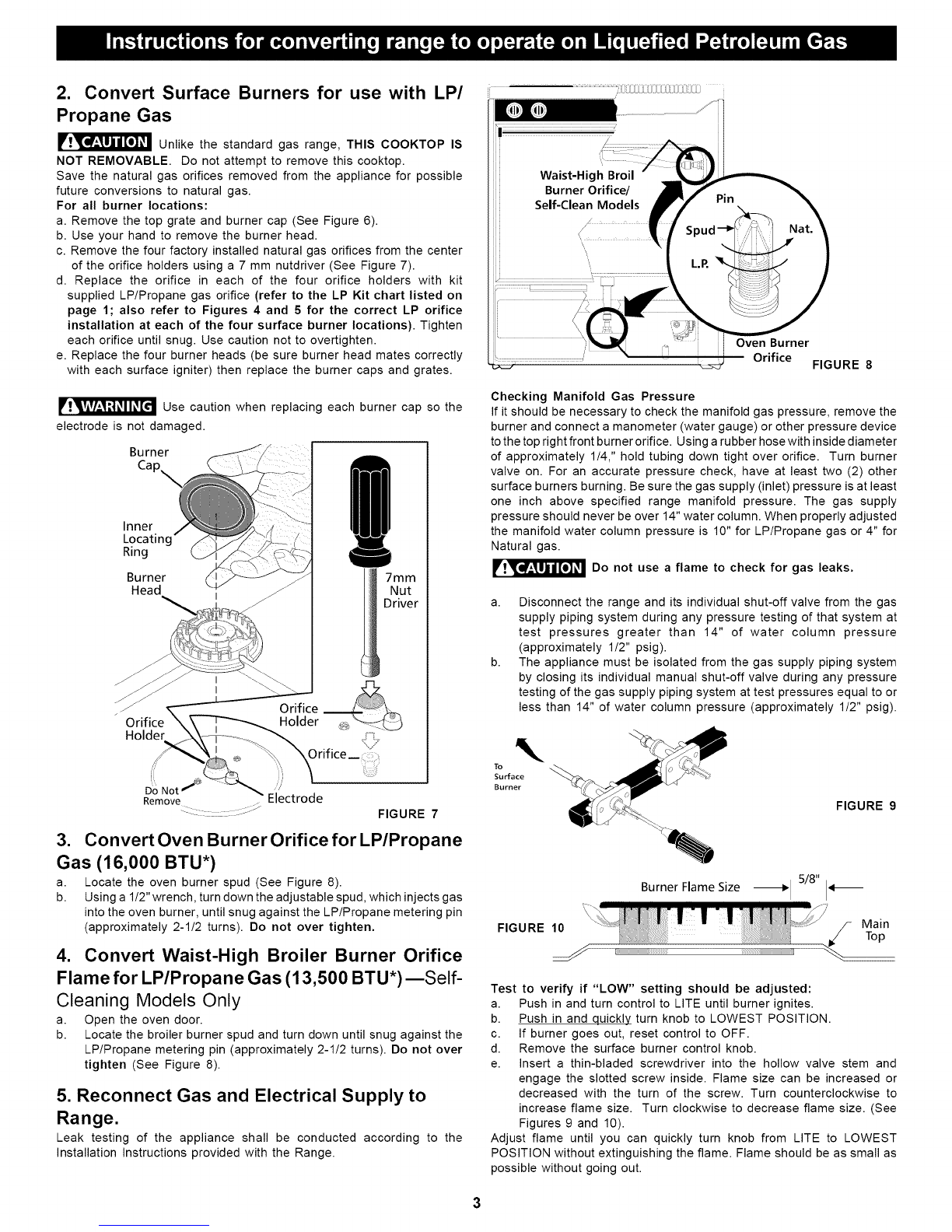
3. Convert Oven Burner Orifice for LP/Propane
Gas (16,000 BTU*)
a. Locate the oven burner spud (See Figure 8).
b. Using a 1/2" wrench, turn down the adjustable spud, which injects gas
into the oven burner, until snug against the LP/Propane metering pin
(approximately 2-1/2 turns). Do not over tighten.
4. Convert Waist-High Broiler Burner Orifice
Flame for LP/Propane Gas (13,500 BTU*)--Self-
Cleaning Models Only
a. Open the oven door.
b. Locate the broiler burner spud and turn down until snug against the
LP/Propane metering pin (approximately 2-1/2 turns). Do not over
tighten (See Figure 8).
5. Reconnect Gas and Electrical Supply to
Range.
Leak testing of the appliance shall be conducted according to the
Installation Instructions provided with the Range.
_,...........................................:i!iiiiiil;ili[iiiii(i;[ii[iiiZiiZiiiiiii(Zi
ii
Oven Burner
Orifice FIGURE 8
Checking Manifold Gas Pressure
If it should be necessary to check the manifold gas pressure, remove the
burner and connect a manometer (water gauge) or other pressure device
to the top right front burner orifice. Using a rubber hose with inside diameter
of approximately 1/4," hold tubing down tight over orifice. Turn burner
valve on. For an accurate pressure check, have at least two (2) other
surface burners burning. Be sure the gas supply (inlet) pressure is at least
one inch above specified range manifold pressure. The gas supply
pressure should never be over 14" water column. When properly adjusted
the manifold water column pressure is 10" for LP/Propane gas or 4" for
Natural gas.
__qJ_ Do not flame to check for leaks.
use a gas
a. Disconnect the range and its individual shut-off valve from the gas
supply piping system during any pressure testing of that system at
test pressures greater than 14" of water column pressure
(approximately 1/2" psig).
b. The appliance must be isolated from the gas supply piping system
by closing its individual manual shut-off valve during any pressure
testing of the gas supply piping system at test pressures equal to or
less than 14" of water column pressure (approximately 1/2" psig).
To
Surface
Burner
FIGURE 10
%
Burner Flame Size
FIGURE 9
Test to verify if "LOW" setting should be adjusted:
a. Push in and turn control to LITE until burner ignites.
b. Push in and quickly turn knob to LOWEST POSITION.
c. If burner goes out, reset control to OFF.
d. Remove the surface burner control knob.
e. Insert a thin-bladed screwdriver into the hollow valve stem and
engage the slotted screw inside. Flame size can be increased or
decreased with the turn of the screw. Turn counterclockwise to
increase flame size. Turn clockwise to decrease flame size. (See
Figures 9 and 10).
Adjust flame until you can quickly turn knob from LITE to LOWEST
POSITION without extinguishing the flame. Flame should be as small as
possible without going out.
7. Air Shutter-Oven Burner
The air shutter for the oven burner may need adjustment, especially if the
unit has been converted for use with LP/Propane gas. The approximate
flame length of the oven burner is 1 inch (distinct inner, blue flame) (See
Figure 11). 1" Flame Burner
11_ Baffle
FIGURE 11
To determine if the oven burner flame is proper:
a. To access the air shutter you must remove the warmer drawer, see
instructions on page 9.
b. Remove the oven bottom by removing the screws at rear of oven
bottom. Lift up the rear of oven bottom and slide toward back of range
to disengage from front of oven front frame.
c. Remove burner baffle by removing nut located on top of baffle and
two screws from front edge of oven front frame. Lift baffle straight
up and out of the oven.
d. Set the oven to bake at 350°F and observe the flame. If the flame is
yellow in color, increase air shutter opening size. If the flame is a
distinct blue color, but lifting away from the burner; reduce the air
shutter opening size.
e. Turn off oven and allow to cool before adjusting air shutter. To adjust
loosen lock-screw (See Figure 12), reposition air shutter, and tighten
lock-screw.
Burner
®
Locking
Screw
FIGURE 12
Air Shutter
Orifice Hood
(Spud)
Retest the burner by repeating step "d" above. When the burner flame is
a distinct blue color burning steady, the air shutter is adjusted correctly.
f. Replace burner baffle and oven bottom.
Lower
Oven Baffle
(Removable) .......
Waist-High Burner
(Self Clean Models)
;_i Air Shutter
J J" t_-
-_kower Oven Bottom
(Removable)
FIGURE 13
8. Air Shutter-Broil Burner
a. Observe the flame to determine ifthe broiler burner flame is properly
adjusted. It should be steady with approximately 1" blue cones and
no yellow or orange flame tips (See Figure 13).
b. If adjustment to the air shutter is necessary, locate the broiler burner
air shutter (See figure 14), loosen shutter lock screw, and adjust to
obtain optimum flame. This will normally be completely open for LP/
Propane gas. If the flame is yellow in color, increase the air shutter
opening size. If the flame is a distinct blue, but lifting away from the
burner, reduce the air shutter opening size. Tighten the shutter set
screw.
Glide
FIGURE 15
Lock Screw
Air Shutter =_
Oven
Burner
Tube
Orifice
Hood
FIGURE 14
9. Replace Storage Drawer or Warmer Drawer
(instructions for warmer drawer):
a. Pull the bearing glides to the front of the chassis glide
(See Figure 15).
b. Align the glide on each side of the drawer with the glide slots on the
range.
c. Push the drawer into the range until levers "click" (approximately 2").
Pull the drawer open again to seat bearing glides into position. If you
do not hear the levers "click" or the bearing glides do not feel
seated remove the drawer and repeat steps "a" through "c",
This will minimize possible damage to the bearing glides.
CONVERSION TO NATURAL GAS
If it becomes necessary to convert the range back to natural gas:
a. Disconnect gas and electrical supply from range.
b. Convert pressure regulator (See step 1), turn cap over so the solid
end of cap faces outward. Place the hollow end of the cap into the
loop end of the dust protector.
c. Remove the four LP orifices using 7mm nutdriver and replace with
the four original factory installed natural gas orifices at their original
locations (See figure 4 for locations).
d. Convert Oven Burner Orifice for Natural Gas by loosening spud
counter-clockwise (approximately 2-1/2 turns; See step 3).
e. Convert Waist-High Broiler Burner Orifice (Self-Cleaning Models
Only) for Natural Gas by loosening spud counter-clockwise
(approximately 2-1/2 turns). (See step 4.)
f. Readjust "LOW" Setting for Surface Burner Valves following
instructions. (See step 6.)
g. Readjust Oven & Broil Burner Air Shutters. (See steps 7 & 8.)
PIN 316248100 (0306) REV C4

This manual suits for next models

18

Other Kenmore Range manuals

Kenmore 790.7523 Series User manual

Kenmore

Kenmore 790.7523 Series User manual

Kenmore 79079014100 User manual

Kenmore

Kenmore 79079014100 User manual

Kenmore 79046353403 User manual

Kenmore

Kenmore 79046353403 User manual

Kenmore Gas double oven range User manual

Kenmore

Kenmore Gas double oven range User manual

Kenmore 970-3356 Series User manual

Kenmore

Kenmore 970-3356 Series User manual

Kenmore 93121 Use Installation instructions

Kenmore

Kenmore 93121 Use Installation instructions

Kenmore 790.9385 Series User manual

Kenmore

Kenmore 790.9385 Series User manual

Kenmore 7010" User manual

Kenmore

Kenmore 7010" User manual

Kenmore ELITE 790.99613 User manual

Kenmore

Kenmore ELITE 790.99613 User manual

Kenmore 911.95875 User manual

Kenmore

Kenmore 911.95875 User manual

Kenmore 79078023300 User manual

Kenmore

Kenmore 79078023300 User manual

Kenmore 790.9245 Series User manual

Kenmore

Kenmore 790.9245 Series User manual

Kenmore Elite 790.9715 series User manual

Kenmore

Kenmore Elite 790.9715 series User manual

Kenmore GAS A GE-SLIDE IN MODEL 790.3103 User manual

Kenmore

Kenmore GAS A GE-SLIDE IN MODEL 790.3103 User manual

Kenmore 790.7131 Series User manual

Kenmore

Kenmore 790.7131 Series User manual

Kenmore 36 " DUAL FUEL RANGE User manual

Kenmore

Kenmore 36 " DUAL FUEL RANGE User manual

Kenmore 9745 - 30 in. Electric Range User manual

Kenmore

Kenmore 9745 - 30 in. Electric Range User manual

Kenmore Drop-in 790.4526 User manual

Kenmore

Kenmore Drop-in 790.4526 User manual

Kenmore 911.62471 User manual

Kenmore

Kenmore 911.62471 User manual

Kenmore 66595274501 User manual

Kenmore

Kenmore 66595274501 User manual

Kenmore 79097602301 User manual

Kenmore

Kenmore 79097602301 User manual

Kenmore 46981 Use Installation instructions

Kenmore

Kenmore 46981 Use Installation instructions

Kenmore 790. 9132 User manual

Kenmore

Kenmore 790. 9132 User manual

Kenmore 790.71191 User manual

Kenmore

Kenmore 790.71191 User manual

Popular Range manuals by other brands

Whirlpool 30" GW399LXU Dimensions

Whirlpool

Whirlpool 30" GW399LXU Dimensions

Bertazzoni PRO304INSX installation guide

Bertazzoni

Bertazzoni PRO304INSX installation guide

Thermador Professional PRO-GRAND PD304 installation instructions

Thermador

Thermador Professional PRO-GRAND PD304 installation instructions

DCS RGTC305SS Use and care guide

DCS

DCS RGTC305SS Use and care guide

Cadco BIR-1C use and care manual

Cadco

Cadco BIR-1C use and care manual

GE JBP64DM Dimensions and installation information

GE

GE JBP64DM Dimensions and installation information

Sharp SSR3065JS installation manual

Sharp

Sharp SSR3065JS installation manual

Whirlpool SF387PEYB4 parts manual

Whirlpool

Whirlpool SF387PEYB4 parts manual

Frigidaire FGF316ASA installation instructions

Frigidaire

Frigidaire FGF316ASA installation instructions

Whirlpool SELF-CLEANING SLIDE-IN GAS RANGES manual 

Whirlpool

Whirlpool SELF-CLEANING SLIDE-IN GAS RANGES manual 

Frigidaire FGGS3075K W/B Specification sheet

Frigidaire

Frigidaire FGGS3075K W/B Specification sheet

Elmira Stove Works 1855 Installation and operating instructions

Elmira Stove Works

Elmira Stove Works 1855 Installation and operating instructions

Inoksan 1KG100L/R instruction manual

Inoksan

Inoksan 1KG100L/R instruction manual

GE JBS55BKBB Dimensions and installation information

GE

GE JBS55BKBB Dimensions and installation information

Amana AGG222VDW user manual

Amana

Amana AGG222VDW user manual

Frigidaire FFEF3050LS Product specifications

Frigidaire

Frigidaire FFEF3050LS Product specifications

Viking D3 Series installation guide

Viking

Viking D3 Series installation guide

GE JS660SLSS owner's manual

GE

GE JS660SLSS owner's manual

manuals.online logo
manuals.online logoBrands
  • About & Mission
  • Contact us
  • Privacy Policy
  • Terms and Conditions

Copyright 2025 Manuals.Online. All Rights Reserved.