manuals.online logo
Brands
  1. Home
  2. •
  3. Brands
  4. •
  5. Kenmore
  6. •
  7. Range
  8. •
  9. Kenmore 79090153406 User manual

Kenmore 79090153406 User manual

1,
INSTALLATION AND SERVICE MUST BE PERFORMED BY A QUAUHED TECHNlaAN.
IMPORTANT: SAVE FOR THE LOCAL ELECTRICAL INSPECTOR'S USE.
READ AND SAVE THESE INSTRUCTIONS FOR FUTURE REFERENCE,
Clearances and Dimensions
a. Provide adequate clearances between tile range and adjacent combustible surfaces.
b. Location--Check location where the range will be installed. Check for proper electrical supply and tile stability of
floor.
c. Dimensions that are shown must be used. Given dimensions provide minimum clearance. Contact surface
must be solid and level.
T
Minimum t Minimurn to
Minimumto 1/16"-t_ _- j 18" cabinetson
wall on either either side
side of range _ _ of range.
I_--- B ------_1
SIDE
VIEW
I_- 13"€_ I
Maximum depth
for cabinets
above range top.
BACK
VIEW
FRONT
VIEW
RANGE
A C
24" 24" 24"
DIMENSIONS
B
25"
A
48"
Maximum
- I ....
45"
36" ± 1/8")
C
\\
bOOg Operl '/ \
* 30" MINIMUM CLEARANCE BETWEENTHETOP OFTHECOOKING SURFACEAND THE BOTTOM OFAN UNPROTECTED
WOOD OR METAL CABINET;OR24" MINIMUM WHEN BOTTOM OFWOOD OR METAL CABINET ISPROTECTEDBY NOT
LESSTHAN I/4" FLAME RETARDANTMILLBOARD COVEREDWITH NOT LESSTHAN NO. 28 MSG SHEETSTEEL,0.015"
STAINLESSSTEEL,0.024" ALUMINUM OR 0.020" COPPER.0" CLEARANCE ISTHE MINIMUM FORTHE REAROF THE
RANGE. FOLLOWALL DIMENSION REQUIREMENTSPROVIDEDABOVE TO PREVENTPROPERTYDAMAGE, POTENTIALFIRE
HAZARD, AND INCORRECTCOUNTERTOPAND CABINET CUTS.
TO ELIMINATE THE RISK OF BURNS OR FIRE BY REACHING OVER HEATED SURFACE UNITS, CABINET STORAGE
SPACE LOCATED ABOVE THE SURFACE UNITS SHOULD BE AVOIDED. IF CABINET STORAGE tSTO BE PROVIDED,
THE RISK CAN BE REDUCED BY INSTALLING A RANGE HOOD THAT PROJECTSHORIZONTALLY A MINIMUM OF 5"
BEYOND THE BOTTOM OF THE CABINETS.
Printed in United States P/N318154301 (0703) Rev.D
2. Install Anti-Tip Bracket(s). (Seeinstructions on
page 4.)
3_ Serial Plate Information
The serial plate is located on the frame and is visible
when the drawer is opened. See the serial plate for
the following information;
A.Model, lot and serial number of range.
B.Kilowatt rating (power requirements).
C.Voltage ratings.
Serial plate location
4. Electrical Connection Requirements
This appliance must be properly installed and grounded
by a qualified technician in accordance with the National
Electrical Code ANS!/NFPA No. 70-qatest edition--and
local electrical code requirements.
This appliance may be connected by means of
permanent "Hard Wiring" or "Power Supply Cord Kit."
When hard wiring, do not leave excess wire in range
compartment. Excess wire in the range compartment
may not allow the access cover to be replaced properly,
and could create a potential electrical hazard if wires
become pinched. Connect only as instructed under
"WIRING INSTRUCTIONS" in sections 6 and 7. When
using flexible conduit or range cable, use flex connector
or range cable strain relief.
NOTE: Only use copper wire in connection to terminal
block.
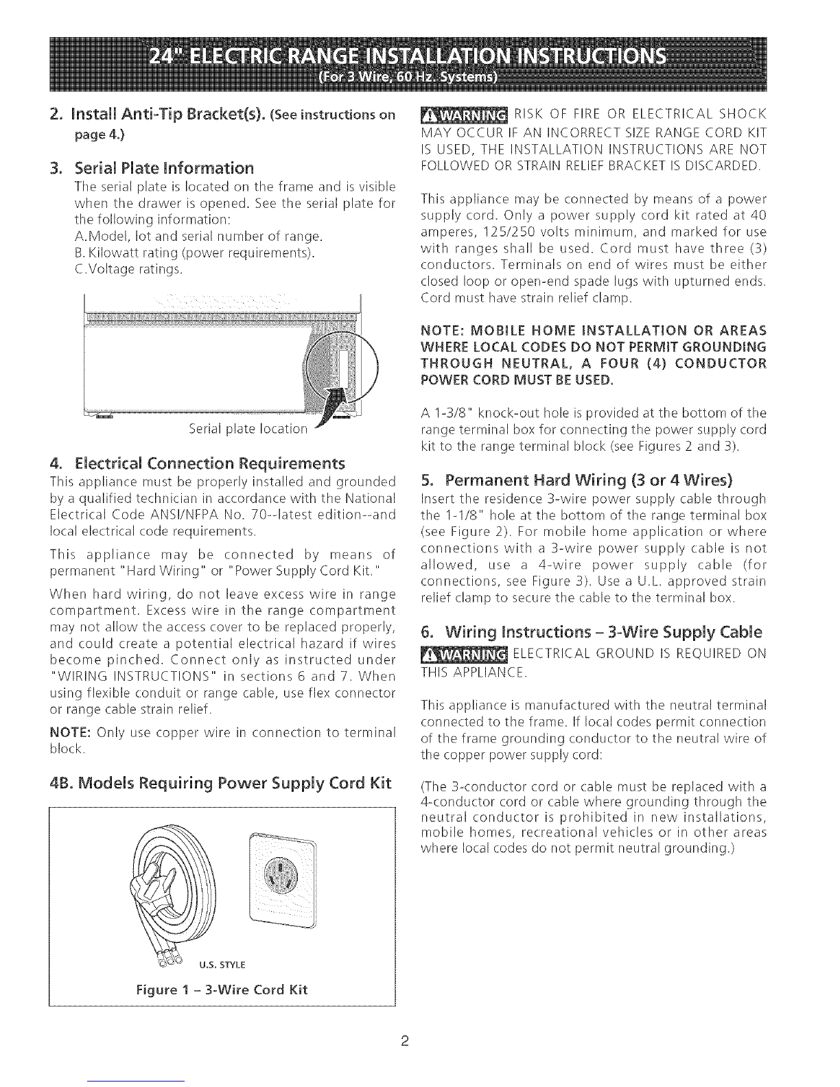
4B. Models Requiring Power Supply Cord Kit
U.S. STYLE
Figure 1 - 3-Wire Cord Kit
RISK OF FIRE OR ELECTRICAL SHOCK
MAY OCCUR IF AN INCORRECT SIZE RANGE CORD KIT
IS USED, THE INSTALLATION INSTRUCTIONS ARE NOT
FOLLOWED OR STRAIN RELIEFBRACKET IS DISCARDED.
This appliance may be connected by means of a power
supply cord. Only a power supply cord kit rated at 40
amperes, 125/250 volts minimum, and marked for use
with ranges shall be used. Cord must have three (3)
conductors. Terminals on end of wires must be either
closed loop or open-end spade lugs with upturned ends.
Cord must have strain relief clamp.
NOTE: MOBILE HOME INSTALLATION OR AREAS
WHERE LOCAL CODES DO NOT PERMIT GROUNDING
THROUGH NEUTRAL, A FOUR (4) CONDUCTOR
POWER CORD MUST BE USED.
A 1-3/8" knock-out hole is provided at the bottom of the
range terminal box for connecting the power supply cord
kit to the range terminal block (see Figures 2 and 3).
5. Permanent Hard Wiring (3 or 4 Wires)
Insert the residence 3-wire power supply (:able through
the I-1/8" hole at the bottom of the range terminal box
(see Figure 2). For mobile home application or where
connections with a 3-wire power supply cable is not
allowed, use a 4-wire power supply cable (for
connections, see Figure 3). Use a U.L. approved strain
relief clamp to secure tile cable to the terminal box.
6. Wiring Instructions - 3°Wire Supply Cable
ELECTRICAL GROUND IS REQUIRED ON
THIS APPLIANCE.
This appliance is manufactured with the neutral terminal
connected to the frame. If local codes permit connection
of the frame grounding conductor to the neutral wire of
the copper power supply cord:
(The 3-conductor cord or (:able must be replaced with a
4-conductor cord or (:able where grounding through the
neutral conductor is prohibited in new installations,
mobile homes, recreational vehicles or in other areas
where local codes do not permit neutral grounding.)
Figure2
A. Remove the 2 screws and remove terminal box
(:over,
B. Remove the 3 loose nuts (after you removed the
rubber band) on the terminal block using 3/8"
nut driver or socket.
C. Attach cable or pigtail to the 3 studs on terminal
block, as local (:odes require. The neutral wire
(white} or center wire must be connected to
center terminal
D. Reinstall terminal box cover.
Do not loosen nuts which secure the
factory installed range wiring to terminal block while
connecting range. Electrical failure or loss of
electrical connection may occur.
GROUNDING INSTRUCTIONS
A ground link is installed on this range which connects
the center terminal of the terminal block (neutral) to the
chassis. The ground link is connected to the range by the
center ground screw. Tile ground link must not be
removed unless national or local codes do not permit use
of tile ground link.
NOTE: If the ground link is removed for any reason, a
separate ground wire must be connected to tile separate
ground screw attached to the range chassis, and to an
adequate ground source.
If used in a mobile home or if local codes do not permit
grounding through the neutral, use ground lead or
ground screw to ground unit in accordance with local
codes. Connect neutral to branch circuit
To Remove Ground Link:
1. Remove ground link
screw using a Phillips
screwdriver. Save screw
for future use.
2. Bend up ground link so
that it does not contact
the range.
Hex nut
Ground
llnk
7. Wiring Instructions - 4=Wire Supply Cable
(Mobile Homes)
Line I
Neutral
(white or
center)
4Wire copper
power supply cord
(40 Arnps) il
TOFUSED ii
D|SCONNECT ii
BOX OR
APPROVED ;;
WIRING DEVICE
FOR COPPER
POWER SUPPLY
.... CORDs
Figure 3
A. Remove the 2 screws and remove terminal box
cover.
B. Remove ground link from terminal box and from
appliance frame. Retain ground screw.
C. Connect ground wire (green) of copper power
supply cord to frame of appliance with ground
screw, using hole in frame where ground strap
was removed (see Figure 3).
D. Connect neutral (white) wire of copper power
supply cord to center silver colored terminal of
terminal box, and connect the other wires to
outer terminals using the 3loose nuts on the
terminal block to terminal box using 3/8" nut
driver or socket.
E. Reinstall terminal box cover.
8. LevelMg the Range
Place a level on a properly installed oven rack. Adjust
tile leveling legs under the bottom corners of the range
until the range is level.
9. AntioTip Bracket Installation Instructions
IMPORTANT SAFETY WARNING
To reduce the risk of tipping of the range, the range
must be secured to the floor by properly installed anti-tip
brackets and screws packed with tile range. Those parts
are located in a plastic bag in the oven. Failure to install
the anti-tip brackets will allow the range to tip over if
excessive weight is placed on an open door or if a child
climbs upon it. Serious injury may result from spilled hot
liquids or from the range itself. Refer to the instructions
on this page for proper installation. If the range is moved
to a different location, the anti-tip brackets must also be
moved and installed with the range.
For the installation intructions refer to the anti-tip
bracket template in a plastic bag in the oven.
4

This manual suits for next models

20

Other Kenmore Range manuals

Kenmore 790. 9132 User manual

Kenmore

Kenmore 790. 9132 User manual

Kenmore 790.4662 User manual

Kenmore

Kenmore 790.4662 User manual

Kenmore 790.9245 Series User manual

Kenmore

Kenmore 790.9245 Series User manual

Kenmore 30" User manual

Kenmore

Kenmore 30" User manual

Kenmore 790.75603 User manual

Kenmore

Kenmore 790.75603 User manual

Kenmore 790.7185 Series User manual

Kenmore

Kenmore 790.7185 Series User manual

Kenmore 790.7050 Series User manual

Kenmore

Kenmore 790.7050 Series User manual

Kenmore 79032623312 Owner's manual

Kenmore

Kenmore 79032623312 Owner's manual

Kenmore 22-70290 User manual

Kenmore

Kenmore 22-70290 User manual

Kenmore 970-6982 Quick reference guide

Kenmore

Kenmore 970-6982 Quick reference guide

Kenmore 790.9654 Series User manual

Kenmore

Kenmore 790.9654 Series User manual

Kenmore 790.9700 Series User manual

Kenmore

Kenmore 790.9700 Series User manual

Kenmore 79090831603 User manual

Kenmore

Kenmore 79090831603 User manual

Kenmore 4558 - 30 in. Electric Drop-In Range User manual

Kenmore

Kenmore 4558 - 30 in. Electric Drop-In Range User manual

Kenmore 790.9507 Series User manual

Kenmore

Kenmore 790.9507 Series User manual

Kenmore 911.95482 User manual

Kenmore

Kenmore 911.95482 User manual

Kenmore 93788 User manual

Kenmore

Kenmore 93788 User manual

Kenmore 66575169300 User manual

Kenmore

Kenmore 66575169300 User manual

Kenmore ELITE 911.99002 Instruction Manual

Kenmore

Kenmore ELITE 911.99002 Instruction Manual

Kenmore 7755 - Elite 30 in. Dual Fuel Range User manual

Kenmore

Kenmore 7755 - Elite 30 in. Dual Fuel Range User manual

Kenmore ELITE 790.9912 Series User manual

Kenmore

Kenmore ELITE 790.9912 Series User manual

Kenmore 61021 User manual

Kenmore

Kenmore 61021 User manual

Kenmore 66572002103 User manual

Kenmore

Kenmore 66572002103 User manual

Kenmore 4559 - 30 in. Electric Drop-In Range User manual

Kenmore

Kenmore 4559 - 30 in. Electric Drop-In Range User manual

Popular Range manuals by other brands

Frigidaire FEF334BGDJ owner's guide

Frigidaire

Frigidaire FEF334BGDJ owner's guide

Smeg SCB60MX8 manual

Smeg

Smeg SCB60MX8 manual

Crosley BEC212ES1 Use & care manual

Crosley

Crosley BEC212ES1 Use & care manual

Dacor Epicure ER36D Planning guide

Dacor

Dacor Epicure ER36D Planning guide

STOVES Sterling R1100E User and installation instructions

STOVES

STOVES Sterling R1100E User and installation instructions

FRICON MPB 90 Maintenance and operation

FRICON

FRICON MPB 90 Maintenance and operation

Viking VDSC367-4G Series Specification sheet

Viking

Viking VDSC367-4G Series Specification sheet

Whirlpool GERC4110PB2 Use & care guide

Whirlpool

Whirlpool GERC4110PB2 Use & care guide

GE Voluson E Series Service manual

GE

GE Voluson E Series Service manual

GE JB750DF2CC owner's manual

GE

GE JB750DF2CC owner's manual

GE Appliances Profile JGB900 Owner's manual and installation instructions

GE

GE Appliances Profile JGB900 Owner's manual and installation instructions

Frigidaire FFES3015LB Product specifications

Frigidaire

Frigidaire FFES3015LB Product specifications

FiveStar TTN260-7BSW installation instructions

FiveStar

FiveStar TTN260-7BSW installation instructions

LG LSIS3018SS owner's manual

LG

LG LSIS3018SS owner's manual

Frigidaire Gallery GLEC36S8E Factory parts catalog

Frigidaire

Frigidaire Gallery GLEC36S8E Factory parts catalog

Samsung NE59M9430 Series user manual

Samsung

Samsung NE59M9430 Series user manual

Molteni Evolution G 200 Specifications

Molteni

Molteni Evolution G 200 Specifications

GE PGB908DEMBB - Profile Series 30" Gas Ran Dimensions and installation information

GE

GE PGB908DEMBB - Profile Series 30" Gas Ran Dimensions and installation information

manuals.online logo
manuals.online logoBrands
  • About & Mission
  • Contact us
  • Privacy Policy
  • Terms and Conditions

Copyright 2025 Manuals.Online. All Rights Reserved.