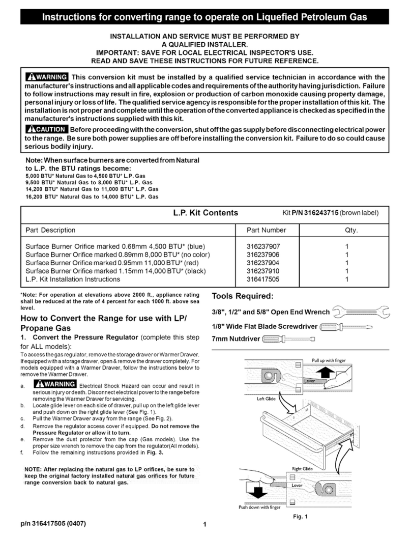
2b. Convert remaining Surface Burners for use with LP/
Propane Gas:
THIS COOKTOP IS NOT REMOVABLE. Do
not attempt to remove the cooktop.
Use caution when replacing each burner cap so
the electrode is not damaged.
a. Remove BRIDGE and SIMMER Burner Caps and SIMMER Burner
Head.
b. Remove4factoryinstallednaturalgasorificesfromtheremainingorifice
holders using a 7 mm nutdriver (See Fig. 13). Note: The BRIDGE Burner
has 3 natural gas orifices to remove.
c. Replace the orifice in each of the 4 orifice holders with kit supplied
LP/Propane gas orifices (refer to the LP Kit chart listed on page 1) Also
refer to Fig. 4 for the correct LP orifice installation at each of the 4 surface
burner locations. Tighten each orifice until snug. Use CAUTION notto
overtighten. The BRIDGE Burner orifice holders are located through the
BRIDGE Burner Head at 3 locations (See Fig.13).
d. Replace all Burner Heads & Burner Caps. Match the letter A located
under center of the SIMMER Burner Cap with the letter A located inside
the SIMMER Burner Head (See Fig. 4). Please note: The 3 BRIDGE
Burner Caps are not marked. Replace the BRIDGE Burner Caps as
illustrated (See Fig. 4).
e. All of the Burner Heads MUST have the Burner Caps correctly installed
to insure proper ignition and gas flame size.
NOTE: The Burner Electrode for the SIMMER Burner must be located
properly in slot of SIMMER Burner Head (See Fig.5).
g. Carefully replaceALL Burner Grates on cooktop.
7turn
Nut
Burner
Head
7rnm
Nut
Driver
.............
Oven Burner
Orifice
Fig. 14
Checking Manifold Gas Pressure
If it should be necessary to check the manifold gas pressure, remove the
burner and connect a manometer (water gauge) or other pressure device
to the top right front burner orifice. Using a rubber hose with inside
diameter of approximately 1/4," hold tubing down tight over orifice. Turn
burner valve on. For an accurate pressure check, have at least two (2)
other surface burners burning. Be sure the gas supply (inlet) pressure
is at least one inch above specified range manifold pressure. The gas
supply pressure should never be over 14" water column. When properly
adjusted the manifold water column pressure is 10" for LP/Propane gas
or 4" for Natural gas.
Do not use a flame to check for gas leaks.
a. Disconnect the range and its individual shut-off valve from the gas
supply piping system during any pressure testing of that system at
test pressures greater than 14" of water column pressure
(approximately 1/2" psig).
b. The appliance must be isolated from the gas supply piping system by
closing its individual manual shut-off valve during any pressure
testing of the gas supply piping system at test pressures equal to or
less than 14" of water column pressure (approximately 1/2" psig).
%
To
Surface
Burner
3_
a.
b.
Left-hand (Bridge) Burner Simmer Burner
Fig. 13
Convert Oven Burner Orifice for LP/Propane Gas
16,000 BTU*
Locate the oven burner spud (See Fig. 14).
Using a1/2" wrench, turn down the adjustable spud, which injects gas
into the oven burner, until snug against the LP/Propane metering pin
(approximately 2-1/2 turns). DO NOT OVER TIGHTEN,
4. Convert Waist-High Broiler Burner Orifice Flame for
LP/Propane Gas (13,500 BTU*) m
a. Open the oven door.
b. Locate the broiler burner spud and turn down until snug againstthe LP/
Propane metering pin (approximately 1 to 1-1/2 turns). Do not over
tighten (See Fig. 14).
5_ Reconnect Gas & Electrical Supply to Range
(complete this step for ALL models):
Leak testing of the appliance shall be conducted according to the
installation instructions provided with the Range.
Fig. 15 _%
Burner Flame Size _1 5/8" i_-
Main
Top
Fig. 16
6. Test to verify if "LOW" setting should be adjusted:
a. Push in & turn control to LITE until burner ignites.
b. Push in & quickly turn knob to LOWEST POSITION.
c. If burner goes out, reset control to OFF.
d. Remove the surface burner control knob.
e. Insert a thin-bladed screwdriver intothe hollowvalve stem and engage
the slotted screw inside. Flame size can be increased or decreased with
the turn of the screw. Turn counterclockwise to increase flame size.
Turn clockwise to decrease flame size. (See Figs. 15 & 16).
Adjust flame until you can quickly turn knob from LITE to LOWEST POSITION
without extinguishing the flame. Flame should be as small as possible
without going out.
