KENT KS-33.5 BR User manual

OWNER'S MANUAL
OPERATION • CARE • SERVICE
BATTERY SWEEPER
KS-33.5 BR
24 VOLT
JULY 1995
083395
https://harrissupplyind.com-ToOrderPartsCall608-268-8080

1
TABLE OF CONTENTS
MACHINE SPECIFICATIONS ............................................................................... 2
SERVICE INFORMATION ..................................................................................... 3
IMPORTANT SAFETY INSTRUCTIONS .............................................................. 3
BATTERY INSTALLATION .................................................................................... 4
WARNING ............................................................................................................. 4
BATTERY CHARGING INSTRUCTIONS .............................................................. 4
INSTRUMENTS AND CONTROLS ....................................................................... 5
HOW TO USE THE MACHINE ............................................................................. 6
ADJUSTMENT OF BRUSHES .............................................................................. 7
HOW TO REPLACE BRUSHES ...........................................................................8
HOW TO CLEAN FILTERS ................................................................................... 9
REPLACEMENT OF CARBON BRUSHES ........................................................ 10
BATTERIES - PERIODIC MAINTENANCE ........................................................ 11
WIRING DIAGRAM ............................................................................................. 12
ILLUSTRATION “A” STEERING COLUMN ASSEMBLY ............................... 13, 14
ILLUSTRATION “B” MAIN BROOM ASSEMBLY .......................................... 15, 16
ILLUSTRATION “C” FLAPS ASSEMBLY ...................................................... 17, 18
ILLUSTRATION “D” FILTERS AND DIRT BOX ASSEMBLY .........................19, 20
ILLUSTRATION “E” POWER DRIVE SYSTEM ASSEMBLY ......................... 21, 22
ILLUSTRATION “F” TRACTION DRIVE SYSTEM ASSEMBLY .................... 23, 24
ILLUSTRATION “G” HOUSING AND PARTS ASSEMBLY ............................ 25, 26
ILLUSTRATION “H” SIDE BROOM AND PARTS ASSEMBLY ...................... 27, 28
ILLUSTRATION “I” BATTERY SYSTEM ASSEMBLY....................................29, 30
https://harrissupplyind.com-ToOrderPartsCall608-268-8080

2
MACHINE SPECIFICATIONS
Model No. ............................................... KS-33.5BR
Type of Sweeper .................................... Rider
Battery System Voltage .......................... 24 Volt
Batteries ................................................. Two 12 Volt, 125AH, P/N 25782
Cleaning Width ....................................... With Side Brush: 33.5 in. (85cm)
Main Brush Only: 23.6 in. (60cm)
Side Brush Diameter .............................. 16.9 in. (43 cm)
Main Brush Length ................................. 23.6 in. (60 cm)
Main Brush Material ............................... Nylon (standard)
Forward Speed ...................................... 0-300 Ft./Min. (5.5 Km./Hr.)
Reverse Speed ...................................... 0-150 Ft./Min. (5.5 Km./Hr.)
Coverage Per Hour @ 300 RPM ........... With Side Brush: 50,250 Ft.ý/Hr. (4,668 mý/Hr.)
With Main Brush Only: 35,400 Ft.ý/Hr. (3,289 mý/Hr.)
Side Broom ............................................ 60 Watt, 24 VDC
Drive Motor (Traction) ............................ 200 Watt, 24 VDC
Filter ....................................................... Three Cartridges - 107 ft.ý(1mý) each
Filter Shaker ........................................... Manual
Dirt Box Capacity ................................... 1,386 in.≈(22,712 cm≈)
Wheels ................................................... Front: (One) Steerable - 7.9 in. (20 cm) dia.
Rear: (Two) Fixed - 6.3 in. (16 cm) dia.
Self-Propelled Directions ....................... Forward and Reverse
Drive Train .............................................. Front Wheel Drive
Speed Control ........................................ Electronic
Features ................................................. Parking Brake
Hour Meter
Remote Side Brush Operation
Remote Front Flap Door
Battery Condition Meter Indicator
Keylock
Battery Charger ...................................... 24/115/60, P/N 031355
Machine Dimensions w/Side Brush ....... Length: 40.1 in. (102 cm)
Body Width: 27.5 in. (70 cm)
Width w/Side Broom: (82 cm)
Height: 41.0 in. (104 cm)
Machine Weight ..................................... With Batteries: 451 lbs. (204.6 Kg)
https://harrissupplyind.com-ToOrderPartsCall608-268-8080

3
SERVICE INFORMATION
To obtain consistent performance over the life of your
Kent equipment, read through these instructions and
save them for future reference. If you require service,
contact the dealer from which the machine was pur-
chased or an authorized service station. Always refer to
your limited warranty for complete service information.
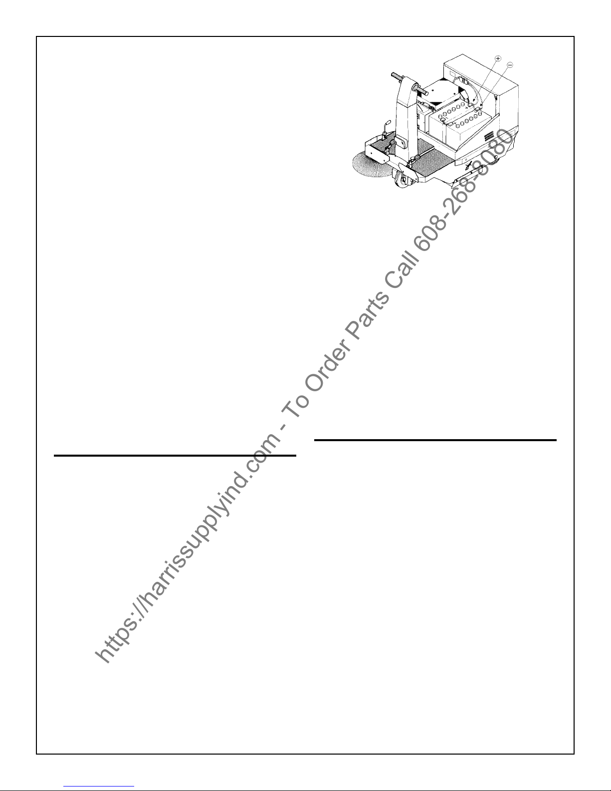
The model, type, and serial number are indicated on
the data plate located on the steel panel, inside the bat-
tery compartment. For prompt and accurate informa-
tion, refer to these numbers when inquiring about ser-
vice.
IMPORTANT SAFETY
INSTRUCTIONS
This manual is a guide for use of the machine and
information concerning the functioning, regulation, and
ordinary maintenance of your new sweeper. Your ma-
chine has been designed and constructed to ensure
maximum performance in a large variety of conditions.
Before delivery, the machine was checked in our fac-
tory to ensure that it will be delivered to you in perfect
condition. To maintain the machine in these conditions
and guarantee functioning without problems, it is very
important that routine maintenance, specified in the
Maintenance section of this manual, be properly per-
formed. Before using the machine, carefully read this
manual and keep it within easy reach for further refer-
ence. Indications of “left” and “right” are referred to in
the direction of movement of the sweeper. If you should
need any further information concerning the sweeper,
contact the dealer from which the machine was pur-
chased or an authorized service station.
This machine must not be used without its protective
equipment. For your own safety, make sure that all pro-
tective devices are closed or correctly in place before
each use of the machine. No safety program is effec-
tive without the total collaboration of the people directly
responsible for the functioning of the machine. The
majority of accidents which occur are a direct result of
the failure to follow the most elementary safety rules.
An alert and cautious operator is the best guarantee
against accidents and is worth more than any preven-
tion program.
SAVE THESE INSTRUCTIONS
READ THIS MANUAL BEFORE
ATTEMPTING TOASSEMBLE OR USE
THIS MACHINE!
SAFETY PRECAUTIONS
FOR THE SAFE OPERATION OF THIS MACHINE,
READ AND UNDERSTAND ALL WARNINGS.
ÿImproper use can cause personal injury.
ÿOperate only when lids, doors, and access panels
are securely closed.
ÿUse care when reversing machine in confined
areas.
ÿWhen servicing the machine, remove the key first
to prevent possible injury.
ÿWhen working with the machine on its side,
remove batteries, clear area of people and
obstructions, and use additional people and
proper procedures when lifting the machine.
ÿYou must have training in the operation of this
machine before using it. READ ALL OF THIS
MANUAL.
ÿDo not operate this machine unless it is com-
pletely assembled. Do not use this machine as a
step or furniture.
ÿBe careful when operating the machine on a
ramp or incline. Always move slowly on a ramp.
Do not turn this machine on a ramp. Do not stop
and leave this machine on a ramp.
ÿTo prevent injury, and damages to the machine,
do not lift the machine or move it to an edge of a
stair or loading dock.
ÿMachines can cause an explosion when operated
near flammable materials and vapors. Do not
use this machine with or near fuels, grain dust,
solvents, thinners, or other flammable materials.
ÿLead acid batteries generate gases that can
cause an explosion. Keep sparks and flames
away from batteries. NO SMOKING! Charge
batteries only in areas with good ventilation.
ÿAlways wear eye protection and protective
clothing when working near batteries. Remove
all jewelry. Do not put tools or other metal
objects across the battery terminals or on the top
surface of a battery.
ÿMaintenance and repairs must be done by
authorized personnel only. Tighten all fasteners.
Keep adjustments according to the specifications
given in this manual for the machine. Keep the
https://harrissupplyind.com-ToOrderPartsCall608-268-8080

4
Figure 1
Connect the batteries as shown; a 1/2 wrench or socket
will be needed. All necessary cable and hardware have
been provided. It is important that all connections made
to the battery are secure.
Periodically check the level of the electrolyte fluid in
each cell and top off when necessary. Add water to
1/4” above the plates. Avoid over filling the cells.
WARNING
When the battery voltage reading on the battery charge
level indicator is 19.0 or less, the batteries must be re-
charged immediately. If this is done, the long life of the
batteries will be ensured. Never use the machine when
only the first green LED is on.
BATTERY CHARGING
INSTRUCTIONS
Follow these instructions for charging the batteries:
1. Disconnect plug connecting batteries.
2. Maintain electrolyte fluid level in batteries.
Check fluid before charging. If needed, fill to 1/
4 inch above the plates, preferably with distilled
water.
3. Insert charging plug into battery receptacle. We
recommend using a battery charger (rectifier) of
the automatic charging control type. To make
this connection possible with any type of battery
charger, each machine is equipped with an
additional connector.
4. Plug power cord into proper AC source.
5. Keep battery cover open while charging.
6. Follow the directions on the charger.
WARNING
Hydrogen gas is formed during the charging opera-
tion and is explosive! Only charge batteries in a well
ventilated area with the lid open. Avoid any open flame
or electrical sparks. Pulling out the charger plug with
the charger on will cause an arc and must be avoided.
electrical parts of the machine dry. For storage,
keep the machine in a building.
ÿMake sure that all labels, decals, warnings,
cautions, and instructions are fastened to the
machine.
ÿDo not turn the steering wheel sharply when the
machine is in motion. The machine is very
responsive to movement of the steering wheel.
Do not make sudden turns.
ÿSweep in straight paths. Do not bump posts. Do
not scrape the sides of the machine.
ÿWhen the machine is in motion, do not reverse
the directional control switch. Switching direction
while in motion puts a very heavy strain on the
motor and drive system.
ÿAlways park on a level surface, turn key off, and
engage parking brake before working on the
machine to keep it from creeping or rolling.
ÿTo prevent damage to the machine and dis-
charges across the tops of the batteries, do not
fill the batteries above the bottom of the tube in
each cell. Wipe any acid from the machine or
the tops of the batteries. Do not add acid to a
battery after installation.
ÿBatteries are heavy. Get help to lift the batteries.
ÿTo prevent an explosion, disconnect the AC plug
from the receptacle before connecting or discon-
necting the DC plug on the charger.
BATTERY INSTALLATION
The machine has been shipped fully assembled and
needs only to have the batteries installed before opera-
tion can begin.
Remove the plastic battery box from the crated bat-
teries and install in machine. Place each of the two
batteries into the plastic battery box in an upright fash-
ion. This box will prevent any damage to the machine
should the battery’s case ever leak. Install each of the
batteries into the machine as illustrated in Figure 1.
https://harrissupplyind.com-ToOrderPartsCall608-268-8080

5
GENERAL INFORMATION AND FUNCTIONAL NOTES
The display 1 incorporates two different instruments: a voltmeter and an hour meter.
Besides giving a reading on the battery level, the voltmeter also includes a device which automatically cuts off all
machine’s functions, except for drive, when battery level is under 19V.
At this point the batteries should be recharged. If this is done the long-life of the batteries is safeguarded (auto-
matic battery chargers should be used). We also recommend checking regularly the level of acid in battery and
topping up if necessary.
The hour meter function is selected by pushing button 4. The display shows first the hours and then the minutes.
After about 10 seconds the hour function is deactivated and the display will return to the battery level reading.
In case of electronic faults, the machine will stop and the display will indicate one of following error codes, each
one corresponding to a different type of fault:
302 = short circuit
306 = overheating of cooling vents
307 = incorrect sequence of key switch/accelerator pedal
308 = potentiometer wire broken
INSTRUMENTS AND CONTROLS
1. Display 8. Side brush lever
2. Main brush warning light 9. Flap raising pedal
3. Light switch 10. Brake blocking device
4. Voltmeter/hour meter selector 11. Brake pedal
5. Brush and vacuum switch 12. Suction blocking control
6. Key switch 13. Filter shaker
7. Drive control
https://harrissupplyind.com-ToOrderPartsCall608-268-8080

6
HOW TO USE THE MACHINE
a) Switch on the machine, turn key 6, wait about 3 seconds until the display indicates battery level.
b) Turn on main brush (button 5).
c) Activate the side brush by lowering lever 8.
d) Check that suction blocking device is not engaged (12).
e) Disengage parking brake (10).
f) At this point turn drive control 7 to make machine move.
g) To pick up light or bulky debris, lift the front rubber flap by pushing down pedal 9 (do not keep pedal down
for too long).
NOTE: The best performance of this machine depends greatly on the state of the filters: they must be
cleaned regularly and every time dirt container is emptied the filter shaker must be used in the
following way:
*cut off suction by means of knob 12.
*pull knob 13 and then let go immediately.
*repeat last operation at least 4-5 times.
h) When work is terminated remember to remove and empty the dirt container.
Warning:
Whenever it is necessary to work on wet floors, remember to deactivate suction by pulling knob 12.
https://harrissupplyind.com-ToOrderPartsCall608-268-8080

7
ADJUSTMENT OF BRUSHES
How to adjust main brush:
(This operation should be carried out on a level floor.)
a) Loosen nuts (Figure C) on both sides of machine and place brush on floor.
b) Lower the brush 1/8 in. by means of the height adjustment nuts on each side of the machine (Figure B).
If the above adjustment has been carried out correctly the brush should leave a 23.6 in. wide clean path on a dirty
floor.
How to adjust side brush:
a) Lower brush by means of lever 1 (Figure A).
b) Loosen the Hand Grip 2 and turn Lever 1 until the brush comes into contact with an area on the floor
corresponding to hypoehetical 11 to 4 o’clock (12 o’clock is equivalent to the direction in which machine is
going).
NOTE: The function of the side brush is to wisk dirt in corners, along walls and in aisles towards the main brush.
https://harrissupplyind.com-ToOrderPartsCall608-268-8080

8
HOW TO REPLACE BRUSHES
Main brush:
a) Remove the dirt container - lower lever (Figure C), keep firm hold on container and remove it by means of
internal handle (Figure D).
b) Remove seat cover and right side hatch (removable).
c) Disengage the brush control belt stretcher by unhooking the spring (Figure B).
d) Lift front of machine up and place a support in the position indicated (Figure A).
e) Remove screws on both sides of machine (Figure E).
f) Remove the right rubber skirt and pull out the brush (Figure F).
Important: Before replacing brush make sure that the bristles are pointing in the right direction and will actually
bring dirt towards the center of the brush.
Side Brush:
a) Remove the dirt container as described above.
b) Lift front of machine up as described above.
c) Remove screw (to loosen turn clockwise) (Figure G).
https://harrissupplyind.com-ToOrderPartsCall608-268-8080

9
HOW TO CLEAN FILTERS
For a thorough cleaning of filters, carry out the following steps:
a) Remove the seat cover and filter cover.
b) Remove hard knobs and pull out the fixing support by pulling back the filter shaker knob (Figure C).
c) Remove filters - first the two on the sides and then the central one (Figure B).
d) Blow with compressed air (max 6 bar) from outside towards inside to avoid possible damage to paper
(Figure A) or clean thoroughly with a tank vacuum and brush.
Before reassembling the filters make sure that they are not torn and that the rubber ring is correctly positioned.
https://harrissupplyind.com-ToOrderPartsCall608-268-8080

10
REPLACEMENT OF CARBON BRUSHES ON ELECTRIC
MOTORS AND FUSES
1) Drive motor (front wheel) (Figure C).
2) Carbon brush protection cap ( N. 2) (Figure C, Pos. 1).
3) Side brush motor (Figure D).
4) Carbon brush protection (N. 2) (Figure D, Pos. 4).
5) Fan/main brush motor (Figure B).
6) Carbon brush protection ring (N. 1) (Figure B, Pos. 6).
7) Carbon brushes (Figure B-C-D, Pos. 7).
8) 3A fuse (headlights) Figure A, Pos. 8).
9) 50A fuse (general) (Figure A, Pos. 9).
To replace carbon brushes:
a) Remove protections.
b) Remove carbon brushes (if worn out) and replace with new ones.
c) Reposition the protections.
Important
The carbon brushes of electric motors should be periodically checked (at least every 200 hours if used on hard
floors and 125 hours if used on carpet) and replaced if worn out. Both the performance and the life of the motors
greatly depend on the state of these components. A worn out brush is 3/8 in. long or less.
https://harrissupplyind.com-ToOrderPartsCall608-268-8080

11
BATTERIES - PERIODIC MAINTENANCE
WARNING: All periodic and extraordinary maintenance must be carried out by competent personnel or by an
authorized Service Center:
NOTES:
The life of the batteries depends on how frequently periodic maintenance is carried out (check of level and
density of electrolyte) and on how much the battery is run down during work: the batteries must not be run down
under the level indicated (min. voltage 19.0) on the volt meter situated on the dashboard.
WARNING:
If used on hard floors:
Check electric motor’s carbon brushes every 200 hours of use.
If used on carpet:
Check electric motor’s carbon brushes every 125 hours of use.
The electric motor’s carbon brushes must be replaced every 500 work hours. A worn out brush is 3/8 in. long
or less.
every every every
CHECK: on delivery 10 hrs. 50 hrs. 100 hrs.
ÿBattery liquid level X X
ÿBattery voltage level X X
ÿBelt tension X X
ÿBrake adjustment X X
ÿElectric system X X
ÿFixing of nuts and screws X
ÿBrush state X
ÿSeals (hopper, filter, and flaps) X X
ÿTest run to check all functions XXXX
GREASE:
ÿDrive chains X
https://harrissupplyind.com-ToOrderPartsCall608-268-8080

© 2002 Printed in USA
Kent/Euroclean
14600 21st Avenue North
Plymouth, MN, 55447-3408
www.eurocleanusa.com
Phone: 800-334-1083
Fax: 866-261-4779
https://harrissupplyind.com-ToOrderPartsCall608-268-8080
Table of contents
Other KENT Floor Machine manuals

KENT
KENT Razor 20 User manual

KENT
KENT SelecTrac 12 User manual

KENT
KENT SelecTrac 17THP User manual

KENT
KENT KA-170 B User manual

KENT
KENT Razor Blade 26D User manual

KENT
KENT Champion 28 User manual

KENT
KENT Blade 28C User manual

KENT
KENT Edge 28B User manual

KENT
KENT Razor Plus 24C User manual

KENT
KENT SelectSpot User manual
Popular Floor Machine manuals by other brands

Edic
Edic GALAXY 2000SX Owner's manual & parts list

Clemas & Co
Clemas & Co HYDROMIST 55 Operator's manual

Kent Euroclean
Kent Euroclean Razor Plus 24D Service manual

Clarke
Clarke Encore S20E Operator's manual

General Equipment
General Equipment RIP-R-STRIPPER FCS16 Operator's manual

Dustbane
Dustbane Hurricane 400 XTT Operation manual