manuals.online logo
Brands
  1. Home
  2. •
  3. Brands
  4. •
  5. Kenwood
  6. •
  7. Recording Equipment
  8. •
  9. Kenwood KGC-6042 User manual

Kenwood KGC-6042 User manual

JOO/\N3>
KGC-6042
GRAPHIC
EQUALIZER
INSTRUCTION
MANUAL
EGALISEUR
GRAPHIQUE
D'EMPLOI
GRAPHIC
EQUALIZER
BEDIENUNGSANLEITUNG
GRAFISCHE
TOONREGELING
GEBRUIKSAANWIJZING
EQUALIZZATORE
GRAFIC
ISTRUZIONI
PER
L’USO
KENWOOD
CORPORATION
©PRINTED
IN
JAPAN
B50-7952-10(K,
E}QMC)
93/12
1110
Gm
ci
|
4
WARNING
TO
PREVENT
ELECTRIC
SHOCK,
FIRE
AND
OTHER
INJURY.
PLEASE
NOTE
THE
FOLLOW-
INGS:
*
The
unit
is
designed
to
be
connected
®
Do
not
place
the
unit,
where
it
will
be
ex-
12
V
DC
and
negative
grounding.
posed
to
direct
sunlight
or
close
to
heat-
ing
device.
e
Do
not
open
enclosure,
such
as
front
panel,
top
or
bottom
cover.
«
Do
not
drop
pieces
of
metal,
needles,
¢
Do
not
place
the
unit
in
areas
of
exces-
coins
and
other
electrically
conductive
sive
dust,
high
numidity
or
on
unstable
materials
into
the
unit.
surfaces.
2
En)
CLEANING
1.
Turn
the
power
off,
before
cleaning
the
unit.
2.
Do
not
use
any
type
of
abrasive
pad,
thin-
ner,
benzine
and
any
such
kind
of
objects.
3.
Wipe
the
front
panel
and
other
exterior
surfaces
of
the
unit
with
a
soft
dry
cloth
or
a
soft
cloth
lightly
moistened
with
a
neutral
detergent.
e
lf
an
abnormal
smell
or
smoke
is
detect-
ed,
immediately
turn
the
power
off.
M@
if
you
have
difficulty
in
installing
the
set
in
your
car,
please
contact
your
KEN-
WOOD
dealer.
(En)
3
aanNe
CONTENTS
Page
@
HOW
TO
USE
THE
CHANNEL
SWITCH..................
ccc
cece
cece
ees
5
©
FQUALIZER
CURVE
ADJUS IMENT
ciicuiccecsiducori
amid
tedericoiietetande
.
6
@®
SUB-WOOFER
ADJUSTMENT
.......
ee
ee
reer
rer
ener
eer
rere
8
®
FADER
ADSUS
TIVIEN
T
siowasecdiccte
mtosacsnaantns
ices
edaiatena
ponder
asnebetens
Sg
SCARE
AND
MAIN
TENANCE
airs
see
secoetninnnnten
wate
va
sudan
vest
oneareueenns
10
@
ACCESSORY
AND
INSTALL
MANNER
..............ccccccaceeeeeeoeeeeneeees
11
BC
ON
INC
WON
ediecorcastensitinca
vik
tedentilantesteasentnaeota
imam
eiateraceianeas:
12
BN
AAO
itaaiaeasdieten
tiga
coterie
bi
asibectiactedtuadiumadbanniea
ane
sen
Sine
13
©
TROUBLESHOO
MING
GUIDE
nix
:Geautntcaerinad
datos
costetseeseeiaseeudeanuees
14
@
SPECIFICA
HONS
ccs
deaeiivatsides
dienes
Sieeiigiieesessdeecesedeedctaesdn
desiccant
15
A
ten)
HOW
TO
USE
THE
CHANNEL
SWITCH
Ee
)
M@
FOR
4-CHANNEL
SYSTEM
Set
the
’’4/2"’
switch
to
‘‘9+2".
{The
sound
is
output
at
the
front
side,
rear
front
as
adjusted
by
2
band
of
parametric
equalizer,
while
at
the
rear
side,
as
ad-
justed
by
9
band
of
graphic
equalizer.)
Mi
FOR
2-CHANNEL
SYSTEM
uo
set
the
4/2”?
switch
to
‘'11°’.
{The
sound
!s
output
both
at
the
front
and
rear
sides,
as
adjusted
by
2
band
of
parametric
equalizer
and
by
9
band
of
graphic
equalizer.)
CAUTION
Turning
ON
the
‘9°
and
‘'2"’
switches,
the
equalization
range
be-
come
+8
dB~
—4
cB.
{En)
5
TU
EQUALIZER
CURVE
ADJUSTMENT
M@TO
EFFECT
THE
9
BAND
EQUALIZER
:
le
he
ap,
|
mind
Press
the
‘’9"’
switch
to
ON.
(The
9
band
equalizer
knob
indicator
is
then
lit
ON
to
output
adjusted
by
the
equalizer.)
—T
ON
MTO
INCREASE
THE
LEVEL
OF
THE
SELECTED
BAND
Move
the
Graphic
equalizer
knob
of
the
band
you
wish
to
adjust
in
the
up-
ward
direction.
(The
level
of
the
frequency
band
cor-
responding
to
the
moved
knob
in-
creases.)
+
12
MAX.:
+12dB
6
(En)
M@
TO
EFFECT
THE
PARAMETRIC
EQUALIZER
Press
the
‘’2’'
switch
to
ON.
(The
parametric
equalizer
knob
indi-
cator
is
then
lit
ON
to
output
sond
ad-
justed
by
the
equalizer.}
Cr
Ty
ON
I
ALUIII
GUI
el
ite),
|
TE
8
a
(EEN
Piola
Ta
‘Li
(s)
|
(
bi
.
-
-*
ee)
e+?
M@
TO
DECREASE
THE
LEVEL
OF
THE
SELECTED
BAND
Move
the
Graphic
equalizer
knob
of
the
band
you
wish
to
adjust
in
the
downward
direction.
(The
level
of
the
frequency
band
cor-
responding
to
the
moved
knob
decreases.)
MAX.:
—12dB
{|
M@
HIGH
FREQUENCY
PARAMETRIC
EQUALIZER
ADJUSTMENT
Set
the
Parametric
frequency
knob
Adjust
the
Parametric
leve!
knob
(HI}
(H!)
to
your
desired
frequency.
so
that
the
frequency
characteristic
feels
likely
to
be
flat
for
your
ears,
:
set
the
Parametric
frequency
knob
Adjust
the
Parametric
level
knob
(LOW)
to
your
desired
frequency.
(LOW)
so
that
the
frequency
charac-
teristic
feels
likely
to
be
flat
for
your
i
v
(En}
7
TT
SUB-WOOFER
ADJUSTMENT
Front/rear
output
characteristic
curve
Press
the
Sub-woofer
switch
to
ON.
Switch
OFF
(Both
the
Level
and
Frequency
knob
indicators
are
then
lit
ON
to
output
the
sub-woofer.)
Switch
ON
=
TT
ON
.
a
:
HUT
KENWOOD
GRAPH
a
cM
OTM
MITT
gC
Cy
|
TERT
[
te)
TTT
rma
|
"lit
|
TEE
3
a
*
7
eo
F
?
Adjust
the
sub-woofer
cut-off
fre-
quency
with
the
Frequency
knob.
Adjust
the
level
of
the
sound
output
from
the
sub-woofers
with
the
Level
knob.
|
:
+
10dB
i
a
30Hz
if
B
ten}
e
With
the
2-channe!
system,
the
normal
output
both
at
the
front
and
rear
sides
is
cut
at
low
with
about
100
Hz.
With
the
4-channel
sys-
tem,
the
normal
output
at
the
rear
side
is
cut
at
low
with
about
100
Hz,
while
at
the
front
side,
it
is
not
cut
at
low.
FADER
ADJUSTMENT
NG
eh
a
ee
@
When
you
wish
to
emphasize
Mi
When
you
wish
tc
emphasize
the
sound
from
the
front
the
sound
from
the
rear
speakers
speakers
Rotate
the
Fader
controller
to
the
left.
Rotate
the
Fader
controller
to
the
aq:
BR
Bere
ob
ee
e
The
sub-woofer
output
is
not
affected
by
the
fader,
(En)
9
os
He
h-
+
CARE
AND
MAINTENANCE
SE
®
The
power
source
of
this
unit
is
exclusively
DC
12
V,
negative
ground.
®
Do
not
place
the
graphic
equalizer
in
a
place
where
the
graphic
equalizer
may
be
exposed
to
direct
sunfight,
heat
or
moisture.
Be
careful
that
meta!
objects
and
water
do
not
enter
the
set.
@
If
you
have
difficulty
in
installing
the
set
in
your
car,
please
contact
your
KENWOOD
dealer.
Cleaning
Clean
with
a
dry
silicone
cloth
or
a
soft
cloth.
The
use
of
thinner,
alcohol
or
other
solvents
may
damage
the
surface
finish.
10
(En)
ACCESSORY
AND
INSTALL
MANNER
Mm
ACCESSORY
Flat
head
screw
(M4
x
6)
Power
con-
nection
cord
Washer
assembly
screw
(M4-~x
8)
Panel
frame
Tapping
screw
(64
x
16)
Side
bracket
Bracket
@
INSTALL
MANNER
1.
Before
installation
and
wiring,
remove
the
{—)
terminal
of
the
battery
to
prevent
shortcir-
cuiting.
.
Connect
the
input
and
output
cords
of
the
system.
.
Connect
the
ground
to
the
meta!
chassis
of
the
car.
.
Connect
the
power
supply
lead
(yellow),
.
Install
the
set
and
after
confirming
the
installation
and
wirings
are
correct,
connect
the
(—)
terminal
of
the
battery.
oI
Ww
AS
¢
Ifa
fuse
is
blown,
first
check
that
the
associated
wires
are
not
short-circuited,
then
replace
the
fuse
with
a
new
one
having
the
same
capacity.
(En)
41
Cassette
receiver
atc.
(optional)
i
it
a}
a)
Ignition
key
Front
right
output
Ae
Een
Front
teft
output
2
Rear
right
output
Power
control
Rear
left
output
Me
rite
ue/Whita)
F
use
Sub-woofer
See
AAEED
right
output
!
Ft
ae
Sub-woofer
é
Power
supply
lead
3h
left
output
(Yellow)
©
=
1
|
=
Ground
lead
(Black)
os
Right
input
i
KGC-6042
rouge
ie
ac
Battery
Left
input
ia
'
(1)
Power
connection
cord
—na—
WU
|
Power
amplifier
(optional)
Sub-woofer
Power
amplifier
1
(optional)
Rear
speaker
Power
amplifier
===)
(optional)
Front
speaker
e
(f
the
RCA
extension
cable
(option-
al}
is
provided
with
a
GND
wire,
then,
fix
it
into
the
threaded
hole
for
GND
on
the
rear
of
the
main
unit,
with
the
(@)
Washer
assem-
“@
bly
screw.
Washer
assembly
screw
12
(En
INSTALLATION
®
When
installing
in
the
car,
choose
the
best
position
with
regard
to
overall
sefety
of
the
system
and
ease
of
operation.
®
As
installation
fixtures,
use
only
the
accessories
supplied.
@
installing
the
unit
in
the
dash
panel:
Convenient
spot
fire
wall
Tapping
screw
Washer
assembly
screw
{M4
x
8)
Console
||
-«
@)
Side
bracket
&)
Flat
head
screw
(M4
x
6}
@)
Panel
frame
@
Tapping
screw
(64x
16}
@
installing
the
unit
below
the
dash
board:
+o
ee
th
ee
eee
eee
Dash
board
(4)
Bracket
Metal
mouning
strap
tapping:aciaw
4h
on
assembly
screw
4
@)
Tapping
screw
{$4
16)
(En)
13
TROUBLESHOOTING
GUIDE
What
often
appears
to
be
a
malfunction
is
often
due
to
user
error
in
operation
or
connection.
When
trouble
occurs
with
your
unit,
please
check
the
following
before
calling
for
service.
Power
cannot
be
|
1.
The
backup
fuse
is
blown.
1.
After
checking
that
no
cords
are
switched
ON,
The
fuse
of
the
connected
head
short-circuited,
replace
the
unit
is
blown.
blown
fuse
with
a
new
one
of
the
specitied
capacity.
2.
Cannect
the
power
connector.
2.
The
equalizer’s
power
connec-
tor
is
not
connected
to
the
pow-
er
supply.
The
Fader
controller
is
turned
fully
|
Turn
the
Fader
controller
to
op-
to
front
or
rear.
timize
the
front/rear
balance.
1.
The
speaker
cord,
system
pow-
|
1.
Conneci
cords
properly
accord-
er,
or
pre-out
connections
are
ing
to
the
instructions
in
the
in-
not
secure,
:
struction
manual.
2.
The
pre-fader
control
of
the
|
2.
Set
the
fader
of
the
head
unit
to
head
unit
is
set
to
the
minimum
the
center
position
and
check
if
position.
sound
is
output.
Low
frequencies
are
not
|
The
Sub-woofer
switch
is
set
to
the
|
Set
the
Sub-woofer
switch
to
the
heard.
ON
position.
OFF
position,
Sound
is
not
heard
from
the
front
or
rear
speakers.
Sound
is
not
output.
14
tens
SPECIFICATIONS
Sa
aa
a
a
a
ae
Specifications
subject
to
change
without
notice.
Equalizer
Section
Equalizer
Center
Frequency
...........
Equalization
Range
..............ceceeeee
Sub-woofer
Cut-off
Frequency.......
Sub-woofer
Output
Gain...........,
Sub-woofer
Cut-off
Slope
.............
Parametric
Equalizer
Frequency....:.
Parametric
Equalization
Range.......
Audio
Section
Input
Impedance
...............c.c.c00e.
Output
Impedance........0.....cceeeaeee
Signal
to
Noise
Ratio
...................
i
Wc
I
Lene
veer
mere
neon
ate
er
me
Frequency
Response
(—3
dB)........
CAN
ia
soeliat
avcteustatrn
tet
pealtec
General
Opexating
Voltage...............2-.2.0002
Current
Consumption
(MAX)
.........
Dimensions
(WxHxD)...
ee,
WV
CIQU
iis.
foe
ibe
oi
asdisn
nn
ea
anlaties
40
Hz,
120
Hz,
250
Hz,
500
Hz,
1
kHz,
2
kHz,
4
kHz,
8
kHz,
16
kHz
—12~+12dB
30
~
150
Hz
(variable)
—«o-~+10dB
12
dB/oct
30~
800
Hz,
800
Hz~16
kHz
(variable}
—1j]2~+12
dB
.
10
kQ
600
0
100
dB
0.01
%
20
Hz~
60
kHz
0
dB
14.4
V
(11~16
V)
O.2A
178
x
25x
150
mm
(7x
1x
5-7/8
in)
0.8
kg
(1.8
Ib)
(En}
15

Other manuals for KGC-6042

2

Other Kenwood Recording Equipment manuals
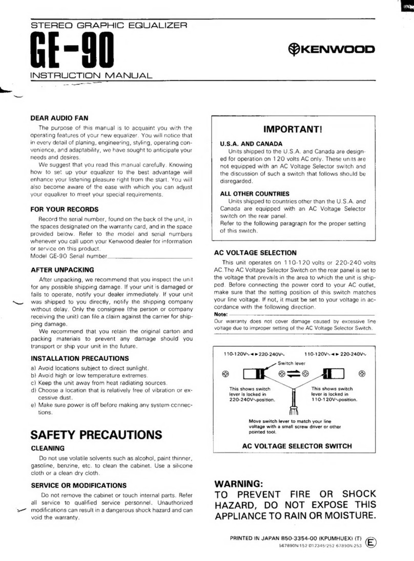
Kenwood KE-894 User manual

Kenwood

Kenwood KE-894 User manual

Kenwood KE-7090 User manual

Kenwood

Kenwood KE-7090 User manual

Kenwood KOS-V1000 User manual

Kenwood

Kenwood KOS-V1000 User manual

Kenwood Nexedge KTI-3 User manual

Kenwood

Kenwood Nexedge KTI-3 User manual

Kenwood Nexedge KTI-3 User manual

Kenwood

Kenwood Nexedge KTI-3 User manual

Kenwood MGR-A7 User manual

Kenwood

Kenwood MGR-A7 User manual

Kenwood TK-930 User manual

Kenwood

Kenwood TK-930 User manual

Kenwood DX-7 User manual

Kenwood

Kenwood DX-7 User manual

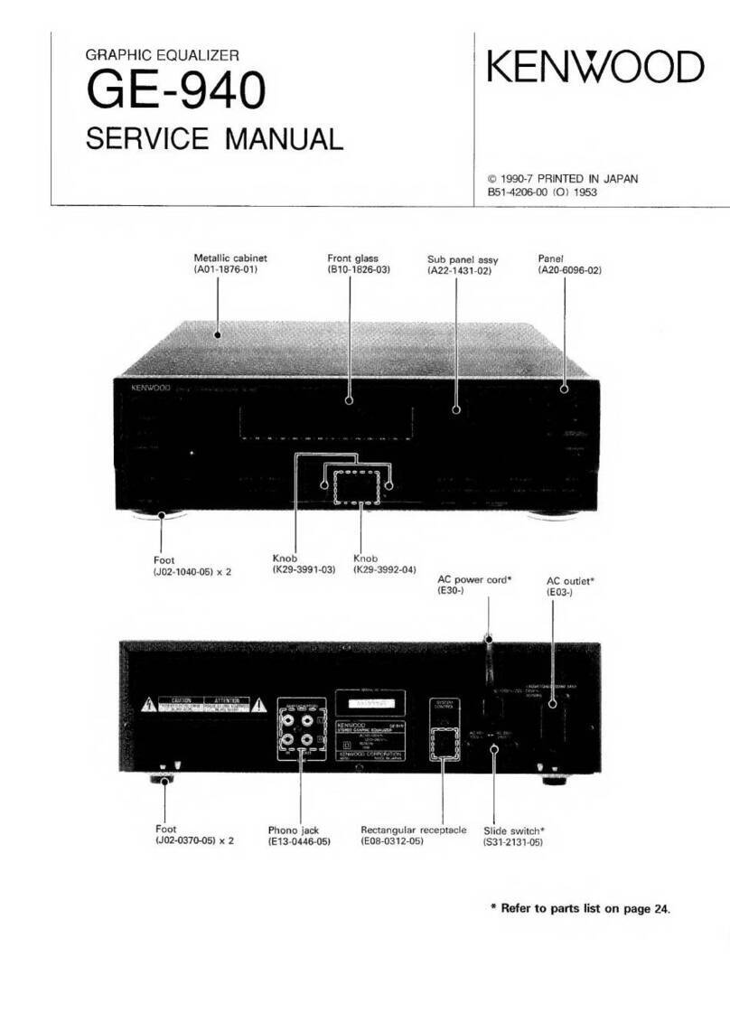
Kenwood GE-940 User manual

Kenwood

Kenwood GE-940 User manual

Kenwood IF-10A User manual

Kenwood

Kenwood IF-10A User manual

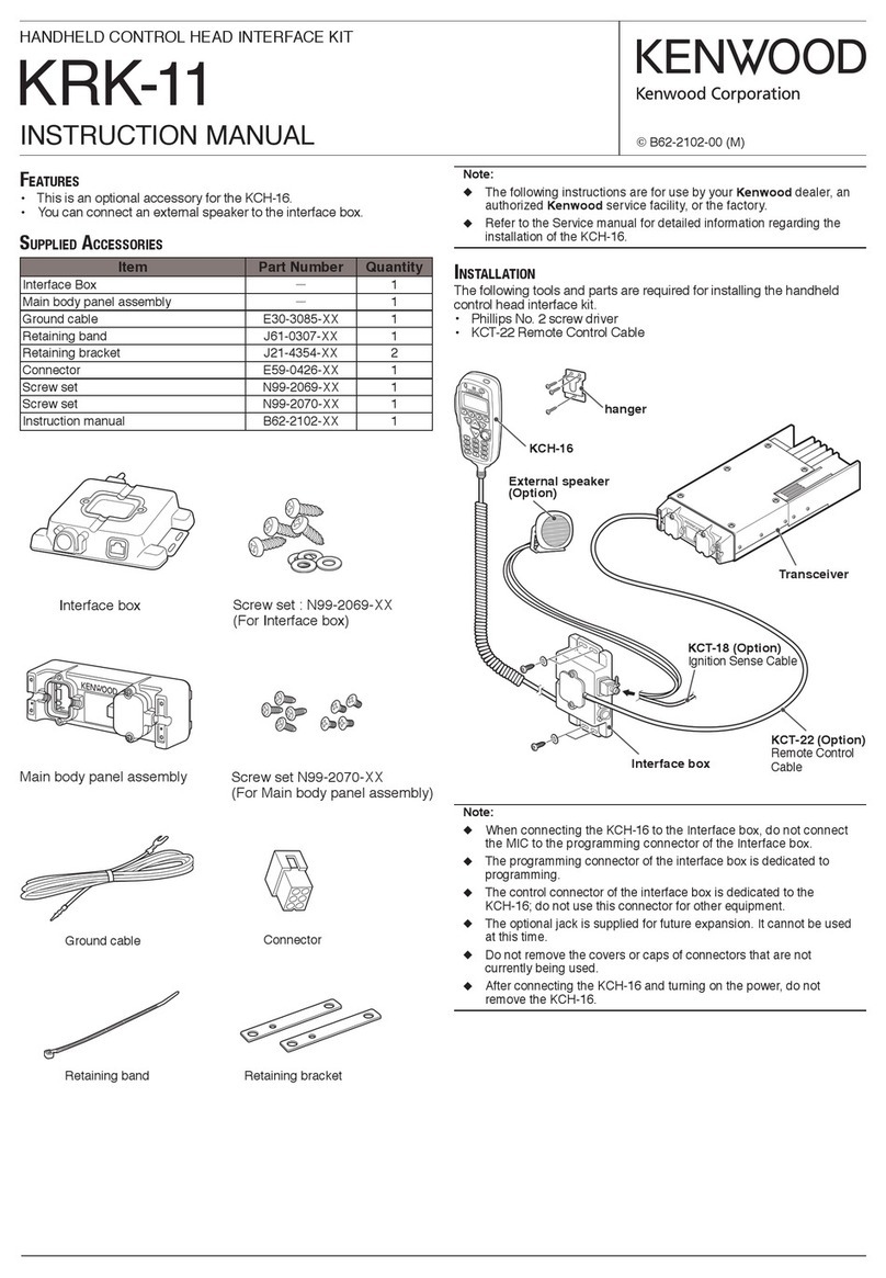
Kenwood KRK-11 User manual

Kenwood

Kenwood KRK-11 User manual

Kenwood GE-7030 User manual

Kenwood

Kenwood GE-7030 User manual

Kenwood GE-9X User manual

Kenwood

Kenwood GE-9X User manual

Kenwood TK-930 User manual

Kenwood

Kenwood TK-930 User manual

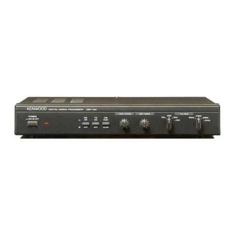
Kenwood DSP-100 User manual

Kenwood

Kenwood DSP-100 User manual

Kenwood KOS-V1000 User manual

Kenwood

Kenwood KOS-V1000 User manual

Kenwood GE-600 User manual

Kenwood

Kenwood GE-600 User manual

Kenwood GE-90 User manual

Kenwood

Kenwood GE-90 User manual

Kenwood GE-4030 User manual

Kenwood

Kenwood GE-4030 User manual

Kenwood MGR-A7 Instruction manual

Kenwood

Kenwood MGR-A7 Instruction manual

Kenwood GE-560 User manual

Kenwood

Kenwood GE-560 User manual

Kenwood KOS-A300 - CarPortal Media Controller User manual

Kenwood

Kenwood KOS-A300 - CarPortal Media Controller User manual

Kenwood KGC-9400 User manual

Kenwood

Kenwood KGC-9400 User manual

Kenwood 4042A - KGC Equalizer / Crossover User manual

Kenwood

Kenwood 4042A - KGC Equalizer / Crossover User manual

Popular Recording Equipment manuals by other brands

Marantz professional AVS user guide

Marantz professional

Marantz professional AVS user guide

Akai MPC 2500 Release notes

Akai

Akai MPC 2500 Release notes

Sierra Video ADM-188 owner's manual

Sierra Video

Sierra Video ADM-188 owner's manual

Retekess TR102 user manual

Retekess

Retekess TR102 user manual

Panasonic AJLT85P - DVC PRO operating instructions

Panasonic

Panasonic AJLT85P - DVC PRO operating instructions

QRS Music Technologies Chili Guide

QRS Music Technologies

QRS Music Technologies Chili Guide

Maag Audio MAGNUM-K user guide

Maag Audio

Maag Audio MAGNUM-K user guide

KUSSMAUL 091-75 instruction manual

KUSSMAUL

KUSSMAUL 091-75 instruction manual

Biamp VOCIA LSI-16 Operation manual

Biamp

Biamp VOCIA LSI-16 Operation manual

Waves Calrec SoundGrid user guide

Waves

Waves Calrec SoundGrid user guide

Festo CPX-CTEL-4-M12-5POL Description

Festo

Festo CPX-CTEL-4-M12-5POL Description

Daktronics Sportsound Gen II quick guide

Daktronics

Daktronics Sportsound Gen II quick guide

Roland GS-10 Read this first

Roland

Roland GS-10 Read this first

Nectar Pacer Using

Nectar

Nectar Pacer Using

Broadcast Tools Audio Sentinel Installation and operation manual

Broadcast Tools

Broadcast Tools Audio Sentinel Installation and operation manual

epiphan DVI Broadcaster DL user guide

epiphan

epiphan DVI Broadcaster DL user guide

Symetrix 528 owner's manual

Symetrix

Symetrix 528 owner's manual

JLCooper Electronics Media Control Station3 user manual

JLCooper Electronics

JLCooper Electronics Media Control Station3 user manual

manuals.online logo
manuals.online logoBrands
  • About & Mission
  • Contact us
  • Privacy Policy
  • Terms and Conditions

Copyright 2025 Manuals.Online. All Rights Reserved.